74_5.0L_Z
-
Posts
1194 -
Joined
-
Last visited
-
Days Won
30
Content Type
Profiles
Forums
Blogs
Events
Gallery
Downloads
Store
Everything posted by 74_5.0L_Z
-

Rear Wheel Stub Axle Play - Help Needed
74_5.0L_Z replied to Wheeler's topic in Brakes, Wheels, Suspension and Chassis
Well I pulled the passenger side strut back out to determine why I still had play and why the torque leveled off around 200 ft-lb. So, I loosened the nut and started to re-torque it. Again as I reached 200 ft-lb, the torque went soft. Well, I turned it a little more and then the torque completely went away. All of the threads on the axle let loose. Now I had a nut on the axle with no threads by which to remove. Several hours later the nut is off, and I am in need of a new axle and nut. -
Cross Member Mounting Points
74_5.0L_Z replied to TieFighter88's topic in Brakes, Wheels, Suspension and Chassis
TieFighter, I just noticed that you are only about 45 minutes from me. If you want, you can come over and take some measurements after the Thanksgiving holiday. Do you plan to autocross when complete? The season starts in January. -
Cross Member Mounting Points
74_5.0L_Z replied to TieFighter88's topic in Brakes, Wheels, Suspension and Chassis
When I built my front frame rails about ten years ago, I went by the 260Z frame drawing for placement of the TC buckets and the crossmember placement. After welding everything up, I discovered that the 260Z FSM had some significant errors. I believe that these errors were corrected in the 280Z FSM but I am not sure. If it were me, I would clamp the crossmember in place and assembly the suspension to make sure everything is correct. You may even want to move the crossmember slightly forward of the stock location to gain a little caster. If you do, make sure that the wheels clear the fenders and air dam. Also if you go too far forward, the steering shaft will not reach. -
Rear Wheel Stub Axle Play - Help Needed
74_5.0L_Z replied to Wheeler's topic in Brakes, Wheels, Suspension and Chassis
I should only be recording 3 decimal places (my bad). I interpolated on the spacer dimension. To measure the housing, I install the inner bearing and then use my Starrett dial calipers to measure from the lip of the outer bearing to the face of the inner bearing. I use it like a depth gage by resting the bottom of the caliper on the ledge of the outer race and let the bar extend hit the face as I open the caliper. I repeated the measurement several times at different clocking around the bore until I was satisfied that I had a reasonably accurate measurement that could be repeated. Thanks John, I will have to get some of that Loctite Bearing lock and see if I can extend the life of the strut housing until I can get a replacement and get it sectioned. I assume that this is the stuff that you mean: http://www.henkelna.com/faceted-search-17046.htm?countryCode=us&BU=industrial&parentredDotUID=productfinder&redDotUID=0000000HWO -
Rear Wheel Stub Axle Play - Help Needed
74_5.0L_Z replied to Wheeler's topic in Brakes, Wheels, Suspension and Chassis
Ok. I finished replacing my wheel bearings yesterday and I also played around with the spacers. My starting condition was that both rear wheel had excessive play, so I replaced all four bearings. While in the process of replacing the bearings I re-measured the spacers and the housings. Here is what I had for both sides: Left Side Right Side Spacer 2.066 2.068 Housing 2.068 2.072 When I pulled the axles out the left side housing provided a good close tolerance / interference fit with the bearing outer races; however, the right side bearings slid out of the housing too easily. After cleaning up the right side housing it looks like I have fretting on the inner housing to outer race surface. Not good, but being the eternal optimist, I assembled everything to see how it felt with new bearings. The left side as expected went together great. There is no measurable axial play and the axle spins very freely. The right side went together weird: The bearings drop into the housing with light hand pressure which was not unexpected because that is how the old bearings fit as well. What is weird is that when torqueing the axle nut, I hit 200 ft-lbs of torque and then the nut continues to turn without an increase in torque. After about two turns at the 200 ft-lb plateau, I decided to stop. In this configuration there is at least 0.006" end play. The torque plateau has me worried. Am I stretching the axle (doubtful unless it is cracked in the treads), or is the fretting corrosion in the housing not letting the bearing seat all the way. Either way, I need to re-torque the axle and see what gives. If the axle is flawed, I want it to break on the bench. If the fretting is preventing the bearing from seating, then maybe the extra torque will (temporarily) fix it. Either way, I need a new right rear strut housing, and perhaps a new right rear axle. Anyone have a spare they want to sell or trade for? What sucks is that the new housing will need to be sectioned to match my old one. We all know how much fun that is. Edited to use proper significant figures. -
Rear Wheel Stub Axle Play - Help Needed
74_5.0L_Z replied to Wheeler's topic in Brakes, Wheels, Suspension and Chassis
This is a timely revival of this thread as I am in the process of replacing my rear wheel bearings. I replaced them once about twelve years ago, and since then I have run hundreds of autocross events with sticky tires. Lately I have an intolerable amount of play in the rear wheel bearings so I have purchased all new rear wheel bearings. So, while measuring the spacers and the housings (both marked B, I found that spacer is right in the middle of the allowable specification (2.068) and the housing is near the maximum tolerance (2.072). I plan to assemble everything today with bearings and see what kind of axial play I end up with. If I still am unsatisfied with the result, I plan to have some new spacers made at my local machine shop. From measuring the existing spacer, I found that the OD is 1.782" and the ID is 1.310" . Available 4130 tubing comes in the following sizes from aircraftspruce: OD Wall Thickness ID 1.625 0.156 1.313 1.750 0.188 1.374 The 1.625 tubing more nearly matches the ID and the 1.75 tubing more nearly matches the OD of the original spacer. I was thinking that the ID will be more important to keep the spacer concentric with the axle. Now I am trying to decide which end of the tolerance to have the new spacers made. Do I have them made to the long end of the allowable (2.0693), or do I have them made to the short end (2.0669)? I think either would work. The longer dimension will push the bearings against the outer surface of the large OD races and the inner surface of the small OD races, and the shorter dimension will reverse the situation. Any thought? -
Ground control vs T3 camber plates
74_5.0L_Z replied to Rob L's topic in Brakes, Wheels, Suspension and Chassis
I have been using the Ground Control camber plates for more than ten years. I have been very happy with them. A feature that makes them very desirable is the spherical surface machined into the bottom of the camber plate between the camber plate and the upper spring perch. This spherical surface allows the spring to align with the strut. I have never had the T3 camber plates in my hands, so I do not know if they have a similar feature. But the pictures that I have seen lead me to believe that they do not. Therefore it appears that as the spring compresses and the strut changes angle relative to the top of the strut tower that the top spring perch will not rotate with the centerline of the strut shaft. If this is the case, the spring will be in bending. If the T3 camber plate does not have a feature that keeps the top of the spring square to the strut, you don't want it. If the T3 does not keep the spring properly aligned then spend the extra money on the Ground Control units. -
JTR Headers - Spark Plug Wires
74_5.0L_Z replied to ktm's topic in Gen III & IV Chevy V8Z Tech Board
That is what I get for choosing a header flange for which there are no available gaskets. However, the RTV works great. No leaks. -
JTR Headers - Spark Plug Wires
74_5.0L_Z replied to ktm's topic in Gen III & IV Chevy V8Z Tech Board
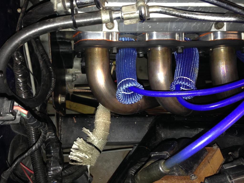
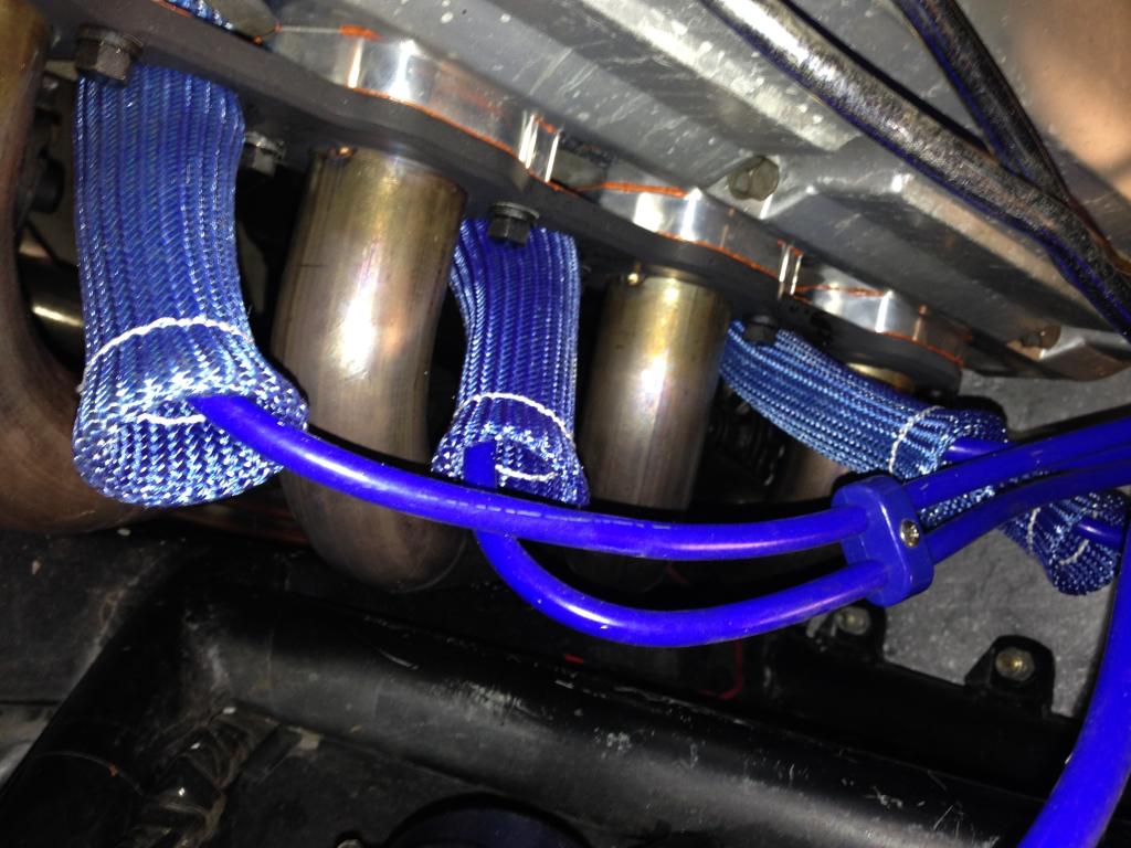
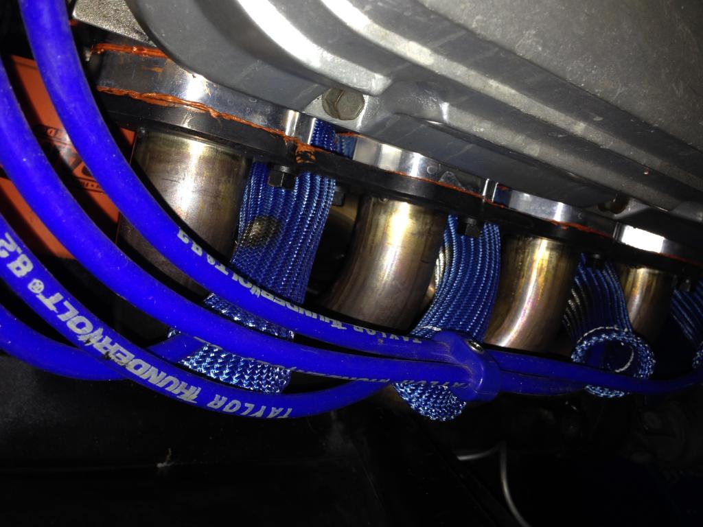
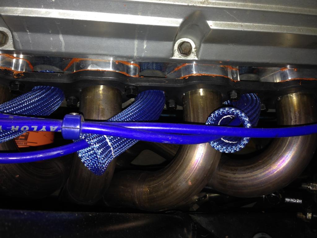
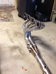
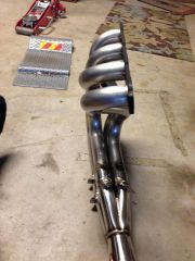
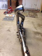
How about a set of these? http://www.ebay.com/itm/8-Cyl-set-Blue-Heat-Protector-Sleeve-Spark-Plug-Wire-Boots-/271289069398?pt=Race_Car_Parts&hash=item3f2a16af56&vxp=mtr I put them on my car after I made my long tube headers. I only have about 100 miles on the car since installing the long tube headers, but I have not yet burned any wires. My car has a stroked 5.0L Ford engine, but has the same kind of issues. They are not the prettiest things, and you can see where some are scorched. The wires underneath are fine.
-
Wheel Fitment Issues
74_5.0L_Z replied to jsausley's topic in Brakes, Wheels, Suspension and Chassis
Remember that these are going on a race car. So these have to be strong and reliable. The diamond racing wheels will be both of those and will be the cheapest option even if they are a bit heavy. The Rotas,Varstoen, and XXR are of dubious quality. I've seen pictures on the web showing catastrophic failure of these wheels. In my opinion, they do not belong on a race car. As mentioned earlier, the Spin Werkes series 82 wheels are about the lowest priced custom wheel that you can get. Unfortunately they are only available in 15" and 16" sizes. I am running 15x10 Spin Werkes wheels with a 5.25" backspace on my car. They weigh 14.9 pounds. edited to remove Rotas as a decent choice. Look under Google for Rota Failure and you will see why. -
Battery relocation to under car in front of fuel tank
74_5.0L_Z replied to BLOZ UP's topic in S30 Series - 240z, 260z, 280z
I have been using an Odyssey PC680MJT mounted on the shelf area behind the passenger seat in my car since 2006. During that time this battery has never let me down unless it was my fault. These batteries work great as long as you use them correctly. Here is the first big mistake that I made: For the longest time I ran a one wire race alternator in combination with under-drive pulleys. This caused me to undercharge at idle. So, during autocross events where I would idle between runs the car would become discharged. It was no big deal as I would charge the battery prior to any given race. I ran the car this way for a couple of years, and during that time I completely discharged the battery probably a hundred times. I have since changed the alternator pulley so that it charges properly at idle. Another mistake that people make with these batteries (Odyssey and Braille) is the use of the wrong type of battery charger. These batteries require the use of specific battery chargers. I have one of the 10 amp chargers listed on this page and it works great: http://www.odysseybattery.com/chargers.html I have put my battery through all manner of abuse over the last seven years. The worst abuse came during a Sebring autocross weekend. Approaching the line for my first run, my hydraulic throw out bearing failed so that I had no clutch. I was determined to get my runs for the day, so I asked the race coordinators if I could leave the line using my starter to get moving. They agreed and I made six back to back runs in which I started the car in second gear on the line using nothing but my odyssey battery. Of course, after the sixth run the battery was completely dead. Even with this abuse the battery still works great. -
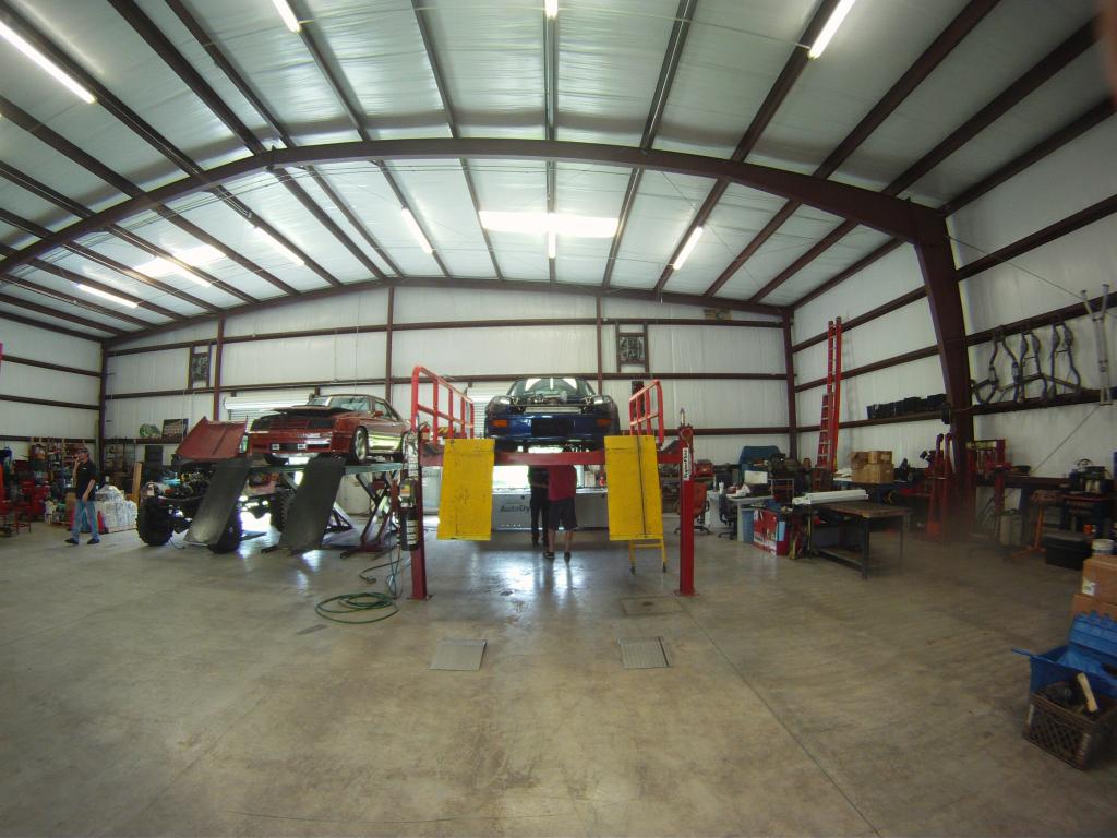
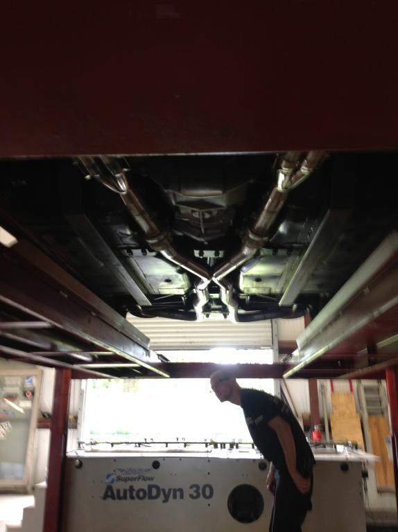
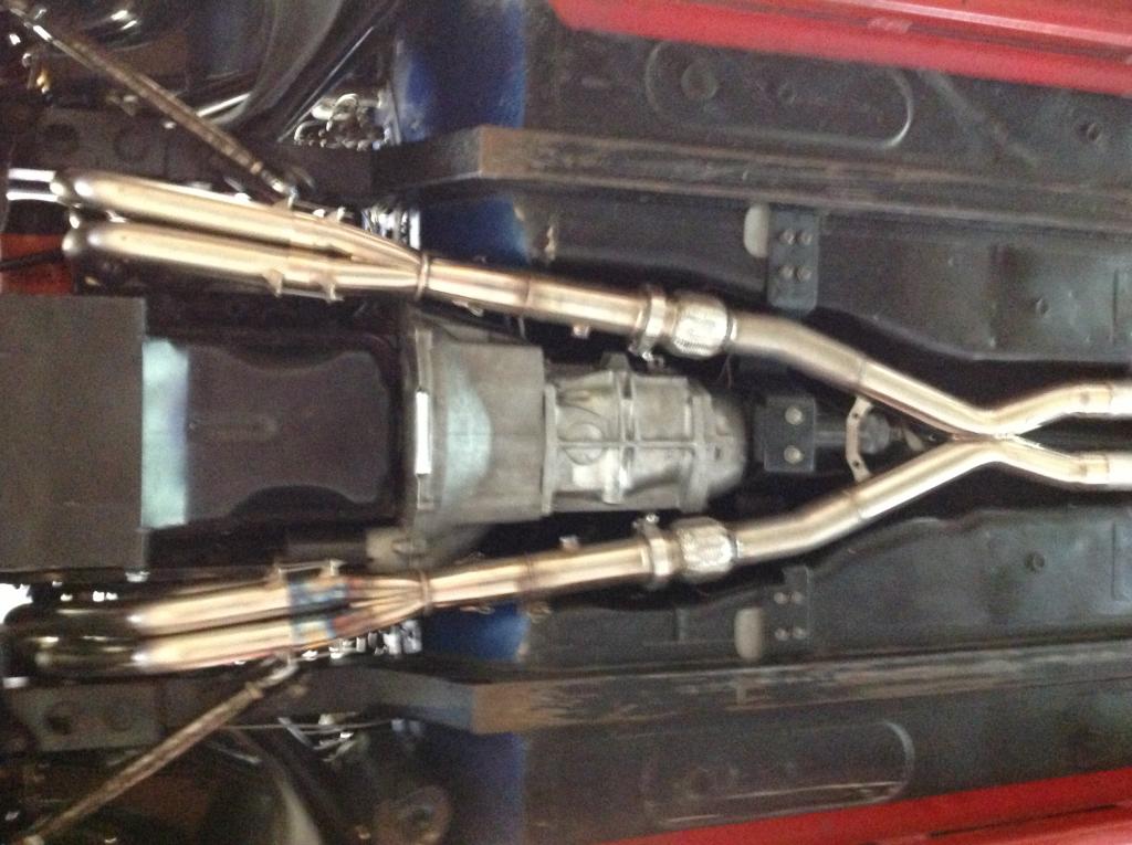
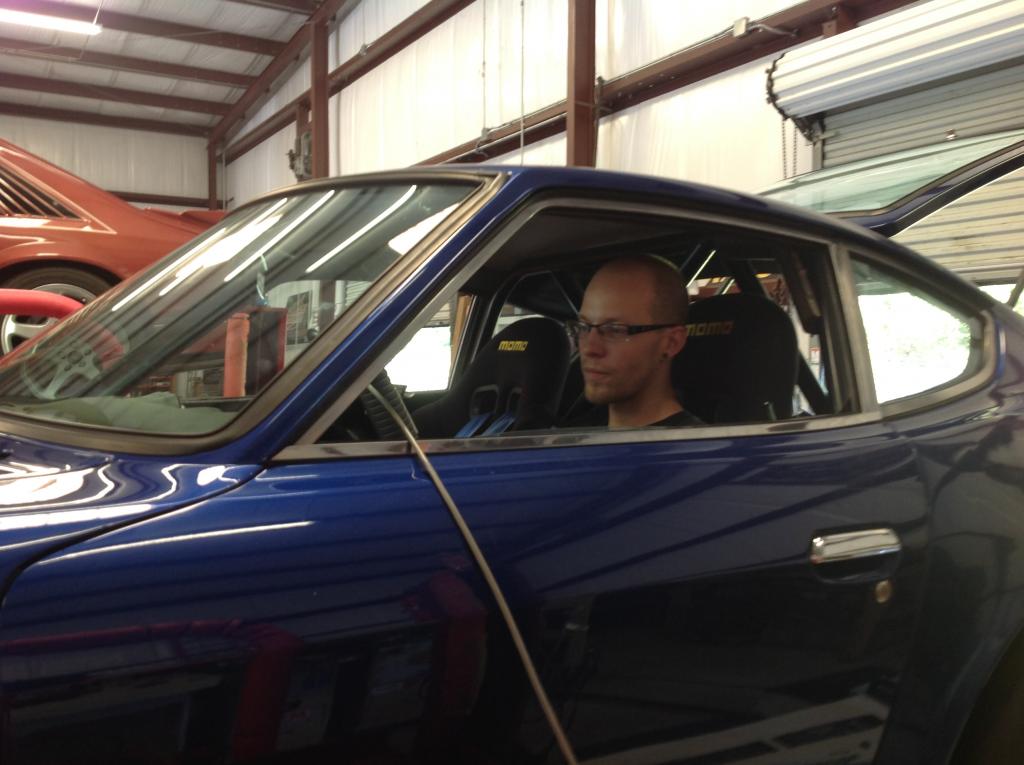
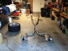
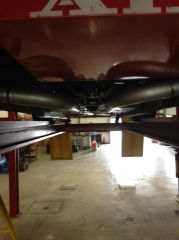
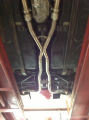
A friend who went with me to do the dyno tuning took some cool pictures of the car and the exhaust with his Go Pro. The first two are good views of the underside of the car and show the layout of the mufflers and fuel cell. The other two are just cool shots of the car and the shop.
-
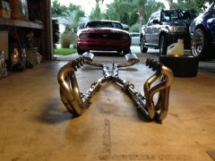
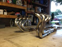
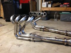
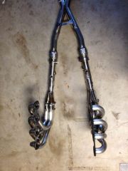
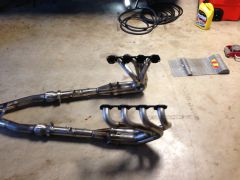
S30 LSX Stainless Steel Long Tube Headers
74_5.0L_Z replied to fullmetaljacket's topic in Gen III & IV Chevy V8Z Tech Board
I used to believe that $1495.00 was expensive for a set of stainless headers until I built my own. These headers look great and are a steal at the price. -
Here are a couple of videos from the dyno session. I apologize for the quality. I am obviously not a cameraman. Dyno1_2.MOV Dyno2.MOV Dyno3.MOV.wmv
-
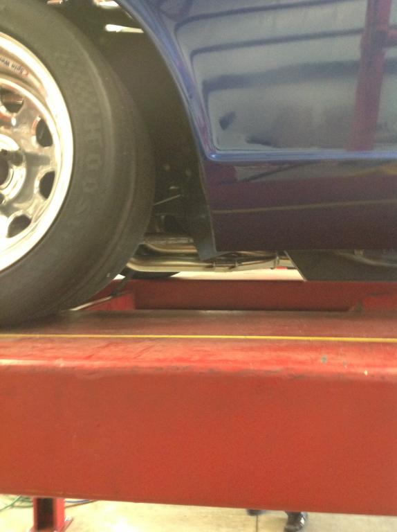
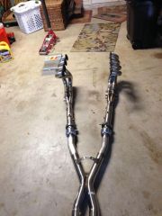
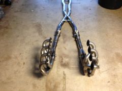
I got the exhaust installed and took the car to the TrickPro Motorsports for some tuning on their SuperFlow dyno. I installed my Ford 327 (5.0L stroker) in 2009 and have been controlling it using a stock A9P EEC-IV computer for several years now. It has run but until now it hasn't been running well. The stock computer was programmed to control a 302 ci engine with 9.2:1 compression and 19 lb/hr injectors. It's not unexpected that it was having trouble controlling a 327 with 10.3:1 compression and 30 lb/hr injectors. Prior to tuning I was able to get some pictures of the installed exhaust while the car was on the lift. Before we started tuning, I wanted to get some baseline runs with the headers installed. The only thing on this car that has changed since the engine was installed in 2009 are the headers and exhaust. So I figured it would be nice to do a comparison. In February 2009 when we broke this engine in on the same dyno, it made 348 rwhp and 365 rwtq. Now in September 2013 after changing the headers and exhaust, the car made a maximum of 385 rwhp and 402 rwtq. I'm really happy with the amount of power that I found with these headers and exhaust system. I am making an additional 37 rwhp and 38 ft-lbs of torque. What was really interesting is that with the old exhaust, the car ran really rich at WOT (~11.5:1 AFR). After changing only the exhaust, the car was running really lean (~16.5:1 AFR at WOT). I'll post videos and dyno charts later in the week. Here are a couple of picture of the car on the dyno: The second picture shows Bryce at TrickPro monitoring O2s and figuring out how to tune the car. When I took the car in it was idling like crap and had idle air fuel mixture of 19.5:1 and 16.5:1 wide open throttle that wandered all over that map. When we left the car was purring like a kitten with stable 15.7:1 idle O2 reading and a solid 12.7:1 wide open throttle air fuel mixture. He programmed a Diablo Sport chip to control the fuel and timing of the computer. While we were at it we also upped the rev limit to 7000 rpms. The thing runs so much better. I had been putting off tuning until I could make my headers and exhaust, but now I wish that I had tuned it long ago.
-
-
-
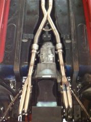
From the album: Creation of New Headers
Installed picture of front portion of exhaust from underside -

From the album: Creation of New Headers
Bryce driving the car on the dyno -
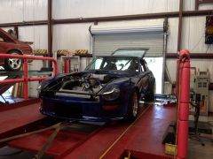
From the album: Creation of New Headers
Car on the dyno at TrickPro Motorsports -

From the album: Creation of New Headers
Installed picture of exhaust from side showing ground clearance -

From the album: Creation of New Headers
Installed picture of exhaust from front showing tunnel / body clearance -
From the album: Creation of New Headers
Installed picture of exhaust from rear showing ground / body clearance -
From the album: Creation of New Headers
Installed picture of back portion of exhaust from underside -
DIY header collectors from www.coneeng.com
74_5.0L_Z replied to JMortensen's topic in Fabrication / Welding
Those are cool. If I hadn't already purchased the slip-on merge collectors that I used then I would definitely have used the Cone Engineering collectors. -
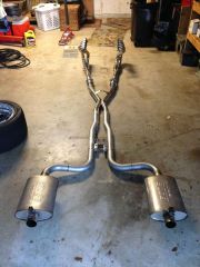
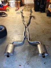
I really like my Borla Pro XS mufflers. Great Sound at full throttle but fairly quiet at idle.