
74_5.0L_Z
-
Posts
1194 -
Joined
-
Last visited
-
Days Won
30
Content Type
Profiles
Forums
Blogs
Events
Gallery
Downloads
Store
Everything posted by 74_5.0L_Z
-
No, I am just using a stock 5.0L block. For the power that I am making and am likely to make in the forseeable future, the stock block is sufficient. Also the stock block is considerably lighter than any of the sturdier replacements.
-
Old engine: 1989 5.0L engine from highway patrol mustang. I got this engine from a junkyard and installed it and the T5 transmission in my car in 2000. When initially installed in my car, the engine was completely stock and had at least 100,000 miles. In completely stock form, the car ran 13.50's at 100mph. I started adding parts after about a year of daily driving. First, I added Ford motorsport 1.72:1 roller rockers, 24# injectors and 73mm MAF. This got the car to 13.20's at 103 mph. Then I added a Cobra Intake, Edelbrock Performer Heads, Crower 15511 cam, and 65mm TB. This got the car to 12.40 at 113 mph. All of this on the stock (100,000 mile plus) bottom end. I drove it this way for about 6 years during which the car saw ~10,000 street miles, ~100 drag strip passes, and about 250 autocross runs. This is the car with the old engine back in november: http://www.youtube.com/watch?v=8HrbHKZyRNo&feature=channel_page Lately, the engine was starting to sound like a lot of loose parts flying in close formation. It rattled a little on start-up, but still ran well, still had good oil pressure, but was starting to smoke a little. So I thought it was time for a new bottom end. New engine: New Ford 5.0L block with stock 4.000 bore. Scat cast steel 3.25 inch stroke crank and 5.400 rods. Mahle 10.3:1 compression forged pistons, rings and pins Fidanza aluminum flywheel Romac Light weight Damper main stud girdle The whole rotating assembly has been dynamically balanced. The heads, cam, and rocker arms are the same parts used on the old engine. I replaced the cobra intake, 65mm TB, and 24# injectors with a Performer RPM intake, 70mm TB, and 30# injectors. I replaced the calibration tube in my 73mm MAF to match the new injectors. The engine is still breathing through the same crappy block hugger headers and exhaust as before. The heads, cam, and exhaust are probably restricting the new engine from making more power, but I don't know that I will be able to use much more for autocross anyways.
-
It will be a little more interesting to autocross than before (it was already a handful). My goal is to have a car that kicks butt in Autocross and that will run 120 mph in the quarter mile. I'll find out soon if I can get the 120 mph run. With the old motor and ~300 whp I ran 113mph through the quarter. With the new engine's dyno numbers, I'm predicting 121 mph in the quarter. The car was already a pretty good autocross weapon with the old engine, and lack of power was never a concern. I will have to adapt to the new engine and also get some bigger tires. Sometime around April, I plan to switch from my current Hoosier 245/45/16 A6's to some 275/35/15 A6's.
-
The "search" is your friend. This thread is a sticky in the Drivetrain section of our site: http://forums.hybridz.org/showthread.php?t=113179&highlight=pull+type+slave
-
After thrashing away in the garage for the last several weeks, I got the new engine running last weekend. I set the initial timing and fuel pressure, and tried to get the car to idle. The engine ran but had a hunting idle and would eventually stall after a few minutes. Well, I took the car to a friends shop, and we put it on his chassis dyno to break in the new engine and do some baseline tuning. This was the first time that I had ever done the chassis dyno thing, and I must say that it was a lot of fun. We strapped the car down on his Superflow AutoDyn 30 chassis dyno, and he set the dyno up so that I could essentially drive the car and put some miles on the engine. After, about the equivalent of 20 miles of varying load, varying speed driving we decided to make a first pull. The first pull netted about 335 rwhp and the O2 sensors were reading about 11.5:1 at idle and would dip to 10.3:1 under full power (black smoke was coming out of the tail pipe). After the first run, we decided that a fuel pressure adjustment was in order. I gave the adjustable fuel pressure regulator 2 turns of adjustment to decrease my fuel pressure and my idle air fuel ratio improved to 12.0:1. We drove the car on the dyno some more to make sure that the AF stayed in the safe region and then made a second pull. This time the peaks were 348 rwhp at 5400 rpm and 363 rwTq at 4500 rpm. The AF ratios were still a bit rich (~11.5:1) under full throttle, but now the car felt a ton better, sounded better, and now would idle without hunting. I made a third run that was pretty much a carbon copy of the second. After that we quit because my pan gasket was leaking a bit. With a little more tuning of the fuel pressure, I think 360 rwhp is attainable, and he says that with a chip we could get even more. We'll do that another day. Here is the graph of the third run:
-
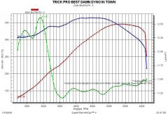 Dyno run of new 327 Ford stroker bottom end. Edelbrock Performer 5.0 heads, Performer RPM intake, 30#/hr injectors, Crower 15511 cam, 70mm TB, 73mm MAF, 1.72 roller rocker arms, 10.3 to mahle pistons. No tuning just a break-in run.
 -
The hypereutectic pistons and forged pistons installed by Ford were approximately the same weight (about 600 gram). As stated earlier the forged are stronger. The good thing about the hypereutectic pistons is that they expand less with temperature and can be run with less wall clearance. Both are fine for an engine that won't use nitrous or supercharging. Over the Christmas holiday I removed the 5.0L from my car (after nearly 9 years of use). During those nine years the car has transitioned from being a daily driver with occasional trips to the drag strip to being a dedicated autocross car. I have always driven it in anger. During that nine years I never touched the stock bottom end, but I have added cam, heads, intake, injectors.... I have finally put together a new stroker short block with a new 5.0L block (4.000 bore), scat stroker crank and rods (3.25" stroke), Mahle Forged pistons (10.3:1 compression), rings and pins. The new Mahle Forged pistons weigh 393 grams. The whole rotating assembly was balanced with a Romac damper and Fidanza aluminum flywheel. I am using the same cam and heads that I had on the old engine, but have switched from a cobra intake with 24# injectors to an Edelbrock Performer RPM with 30# injectors. The new engine is in the car. I started it yesterday for the first time. I'm going to the dyno on thursday. I can't wait.
-

Tips for installing brake bias valve?
74_5.0L_Z replied to heavy85's topic in Brakes, Wheels, Suspension and Chassis
Does the Miata have M10x1.25 fittings or the more common M10x1.0? -
Tips for installing brake bias valve?
74_5.0L_Z replied to heavy85's topic in Brakes, Wheels, Suspension and Chassis
Don't use compression fittings in a brake system! You can however use Inverted flare couplers like Zmanco. If you look at his image here you will see that he replaced the factory proportioning valve with two couplers: http://forums.hybridz.org/attachment.php?attachmentid=11342&d=1231570198 One of the couplers (upper) just connects the line going to the passenger side front brake. The other coupler is the one of interest. What he has done is take the line from the brake splitter that would normally go to the rear brakes and has routed it through the firewall to a proportioning valve mounted inside the car. He then runs the tube from the outlet of the proportioning valve back out through the firewall to the lower coupler which is in the line that normally goes to the rear brakes. This is not a bad way to get the job done if you don't wish to remove the transmission. I had mine installed in a similar fashion for a long time. Later, when I had the transmission out for a clutch replacement, I cleaned up the installation. -
Tips for installing brake bias valve?
74_5.0L_Z replied to heavy85's topic in Brakes, Wheels, Suspension and Chassis
The factory brake lines are M10-1.25 inverted flare. All of the proportioning valves that I have seen have 1/8" NPT threads and come with 1/8" NPT to 3/16 SAE inverted flare adapters. SAE 3/16 I.F fittings have a 3/8-24 female threads. Ideally, you would buy 1/8" NPT to M10-1.25 I.F adapters and be done. Unfortunately, I have yet to find such an animal. What I have been able to find are brake line assemblies that have a M10-1.25 fitting on one end and 3/8-24 fittings on the other. I have also been able to find M10-1.25 to 3/16 SAE adapters. Both of these items are made by Dorman and are available through most auto parts stores. I got mine at NAPA. So what you end up with is one of the special brake line assemblies (M10-1.25 / 3/8-24) from the master cylinder or brake splitter going to the rear wheels. Then you have the proportioning valve with 3/8-24/NPT inlet and outlet fittings. From there, I run a long line that has SAE fittings on both ends. The long line runs from the outlet of the proportioning valve to the inlet of the Tee above the differential. The inlet of the tee has an SAE to M10-1.25 adapter installed. I hope this helps. -
If the V8 was in a Mustang (87-93) LX or otherwise, then it is an H.O. The GT was a body/dress package (hatch back, stripes, better interior). Many people seek out the LX V8 cars because they were lighter than the GT's. The 5.0L engine from the Mustang LX is the same as the 5.0L engine from the Mustang GT. Non-HO 5.0L engines were installed in Thunderbirds, trucks, and other non-mustang fords. The non-HO 5.0L engines had different heads and intake manifolds (as well as smaller 16 lb/hr injectors) The engine that is in my car was from a 1989 Mustang Highway Patrol vehicle. The highway patrol vehicles were V8 LX cars.
-
Odyssey batteries, Good or Bad?
74_5.0L_Z replied to lgoodson@pacbell.net's topic in Ignition and Electrical
I have had my Odyssey PC680 for about 3 years. I been very happy with it. At the last autocross event, my clutch master cylinder failed. I was completely unable to shift the car. My solution was to put the car in second gear and start the car in gear on the starting line. Not the fastest way to get started, but it allowed me to make my five runs. The Odyssey battery pulled my car about ten feet on the starter for each of the five runs before the car started. After the five runs, I used the starter to pull the car onto the trailer. At that point, the battery was dead. Am I happy with the Odyssey? You bet. Just don't leave the lights on. Here is a link to video showing me start the car on the line in second gear without a clutch: http://blip.tv/file/1376878 -
Why go to the trouble of milling an adapter when there are one's available for purchase (reasonably priced). Here is one of many threads that discuss driveshafts: http://forums.hybridz.org/showthread.php?t=75715&highlight=neapco The part number(s) for the adapter is given within. There are two flanges available for the R200 and two different adapters. Make sure you measure so that you get the correct one.
-
Three degrees will work fine. Mine is installed with the tail shaft angled 2.5 degrees down. Just make sure that you adjust the angle of the differential to match the angle of the engine or you will have vibration problems.
-
The best explanation of driveshaft angles that I have seen is provided by Pete Paraska (a premier HybridZ member) on his site: http://alteredz.com/drivelinemods.htm
-
Yet another Rear control arm design
74_5.0L_Z replied to tholt's topic in Brakes, Wheels, Suspension and Chassis
I just got the new ChassisShop catalog. The weld in ends (AKA tube adapters) are listed on pages 9 and 10. Here is a link to help you find the tube adapters on their web page: http://secure.chassisshop.com/categories/5625/ Finding them through their web menu was impossible. I had to search their site using the key words, "tube adapters." -
The car is just a lot easier to drive with a passenger. The improvement manifests itself in the transitions. By that, I mean that the car is easier to drive into and out of the corners. I ran the car at Sebring in October, and I had an in-car camera on board for the first time. During the two day event, I made 14 runs (8 with a passenger on board and 6 by myself). Looking at the videos, it seems that the car is just a lot more prone to oversteer when I am alone in the car (both at corner entry and exit). I did weight transfer worksheets for both conditions, and the worksheet predicts more bias toward understeer when a passenger is on board. What this is telling me is that I need to do some combination of the following: 1. Bigger rear tires (the downside would be the inability to rotate tires between events). 2. Stiffer front springs (just slightly). 3. Softer rear springs (again just slightly) 4. Slightly stiffer front sway bar, or increased sway bar motion ratio. I plan to go with bigger tires next year. This year I had 245/45/16. Next year, I will probably run 275/35/15. I am on the prowl for some light weight 15x10 wheels.
-
Also, depending on which engine you use, nothing says that the crossmember has to be at the front of the frame. Because I wanted to angle my radiator, and because I have a Ford V8 in a very set-back location, I elected to move my crossmember back even with the sway bar mounts.
-
Jon's 2 year roll cage saga...
74_5.0L_Z replied to JMortensen's topic in Brakes, Wheels, Suspension and Chassis
Looking good Jon. I especially like the routing of the tubes to the front strut towers. -
Silly question: Do you have a forward rotation water pump on that motor? The factory water pumps that came in the 1982-1995 mustang had reverse rotation water pumps (the water pump and crank shaft rotated in opposite directions). If you try to turn the reverse rotation pump in the forward direction, then it will not pump water properly through the engine. With a reverse rotation pump, you need an idler pulley to control the belt tension and to provide belt contact around the water pump pulley. Here is my solution: The tensioner pulley came from Steeda, the mounting brackets for the tensioner are custom, and the belt is 49.5 inches. If you decide to go with Vee belts, try march performance. They have a very wide selection of pulleys and brackets (both vee belt and serpentine). Your alternator mounting should be fine. Mine is mounted with the centerline if the alternator pulley lower than the centeline of the crank pulley. I have about 1/4" between the alternator and the boot on the steering rack.
-
Is the accelerated wear occurring on all four corners, or is it happening more on the front or more on the back? How often do you swap the tires from front to back? What are your alignment settings? What do the temperatures look like in the middle of the tire? Regardless of tire temperatures, if the inside and middle aren't wearing but the outside, I would add more negative camber. I have't used the radial slicks, so I dont how much air pressure is typical. I run 32 psi in rear and 36 psi in the front with my Hoosier A6 tires. I swap the tires front to rear every other event (approximately every 10 runs). I put the Hoosier A6 tires on in May and now have about 50-60 runs on them. This set of tires is wearing very well compared to the two previous sets that I had on the car (Hoosier A3S04, and Kumho V700). The outside edge has gotten just slightly rounded, but not bad. I plan to flip them on their rims and swap sides before my next event in two weeks. I should be able to get better than 100 runs on this set of tires if the wear stays consistent. I think the main reason why this set of tires is wearing so much better than my previous tires is that I went with a much stiffer set-up. The car previously had 200 lb/in front and 250 lb/in rear springs with a 1" front sway bar, and now has 450 lb/in front and 425 lb/in rear springs with a 20mm front sway bar. Good luck and sorry for the ramble, but its 2 AM and I can't sleep....
-
I started with the subtle Z kit and made it my own. I added the bottom, bumper feature, and radiator inlet to the front air dam. I cut the hood apart, moved the hump back 25", and built the radiator outlet. I also added a more rounded leading edge to the hood. The hood is mounted using 6 dzus fasteners. The front four dzus fasteners attach to custom hinges, and the rear two attach to brackets on the firewall. If I loosen the two rear dzus fasteners the hood opens as normal. If I remove all 6, I can remove the hood. I have blended a set of stock fiberglass headlight buckets into the Subtle Z fenders.
-
Reduce Understeer?
74_5.0L_Z replied to Rustyfriend's topic in Brakes, Wheels, Suspension and Chassis
Start with the basics and give us some more information: What are your suspension settings? (Caster, Camber, Toe in front, and camber and toe in the rear) Which sway bars are you running front and rear? If this was your first autocross some of the front end push was probably driver induced. You may have been going into the corner too hot and trying to steer while still on the brakes. Its better to get your braking done in a straight line then turn the wheel as you remove your foot from the brake pedal. Oops: Johnc beat me to the punch. -
It does not look as if the top of the strut tower or the suspension attach points on the frame have moved. I also do not see that damage compromising the structural integrity of the front end (at least not much). I would not have any problem using that car especially since you plan to install a cage. I would make sure that you either tie the cage into the front strut towers, or install some form of strut tower brace. Strut tower bracing is good practice for any Z that will be used for high performance driving regardless of previous front end damage.
-
Yet another Rear control arm design
74_5.0L_Z replied to tholt's topic in Brakes, Wheels, Suspension and Chassis
First, the toe link does not need to be perpendicular to the strut housing. So you can gain a little length by moving the inboard end of the toe link toward the front of the car. Second, you might try 5/8" rod end for the toe links. The 5/8" rod ends are a bit shorter than the 3/4" rod ends. Besides, the toe link will not be nearly as stressed as the fixed rod end. As far as turnbuckles go, make your own using these weld-in end from ChassisShop: http://secure.chassisshop.com/partlist/502/ Be sure to buy matching left hand and right hand adapters, cut your tube, weld them up, and Voila. You've got a turnbuckle.