
74_5.0L_Z
-
Posts
1194 -
Joined
-
Last visited
-
Days Won
30
Content Type
Profiles
Forums
Blogs
Events
Gallery
Downloads
Store
Everything posted by 74_5.0L_Z
-
 Where am I going with all of this? I'm working through chapter 16 of Race Car Vehicle dynamics because I'm an engineering geek, and because I want to have a better understanding of how my existing suspension works before I change it. Chapter 16 deals with ride and roll rates and requires that you have knowledge of the following before you can do any meaningful calculations: Corner weights (been there done that) http://forums.hybridz.org/showthread.php?t=92703&highlight=corner+weights Unsprung weight (check) Motion ratios (check) http://forums.hybridz.org/showthread.php?t=129623&highlight=motion+ratios Front and rear Roll center heights (That's next) Center of gravity height (I would like to do this but I may have to estimate) Tire Spring rate (This would be nice, but I'm not holding my breathe). Does anyone have a good ballpark figure? In parallel I plan to work through some of the Chapter 6 stability analysis. As I said, "I'm a geek".
 -
The weight of the Group B items is divided by two because one end is fixed to the sprung mass, and the other is moving with the unsprung mass. The approximation of 1/2 applied for the Group B items (control arms, half shafts, tie rod) assumes symmetry and introduces a small error for items whose mass is not evenly distributed. Fortunately,(or unfortunately) the weights all of the Group B items are small compared to the Group A items. All of the Group A items are 100% unsprung, and no approximation was necessary. The error from approximation of the Group B items is very small compared to the overall unsprung mass.
-
I was pretty surprized as well. As you can see, the wheel/tire and the brake rotors are the heavy hitters.
-
Today, I spent the entire day in the garage weighing and measuring suspension components. This is all in an effort to quantify my unspung weight and also to get a good handle on my instant centers. I'll publish my results for the unspung weight here: Front: Group A: Strut housing with hub, lug nuts, and brake disc_________31.0 lbs Ball joint and steering arm ___________________________2.6 lbs Wheel and tire (Hoosier A3S04 245/45/16)______________39.6 lbs Caliper and pads (Outlaw 2800 caliper w/Hawk 237 HP+) __4.5 lbs Group B: Lower Control Arm __________________________________2.4 lbs T/C Rod Assembly __________________________________2.8 lbs Strut Insert (Koni 8610-1149) ________________________4.3 lbs Tie rod ___________________________________________1.4 lbs Spring (Eibach 10" x 2.5" x 200 lb) ____________________2.9 lbs To get the total front unsprung weight for one corner you sum the items in Group A and add half of the sum of the items in Group B. The total for the front is 82.5 lbs. Rear: Group A: Strut Housing with brake rotor, stub axle, spindle pin, CV adapter,caliper adapter, and lug nuts.__________________________________________________42 lbs wheel and tire (Hoosier A3S04 245/45/16) ___________________39.6 lbs Caliper and pads (Outlaw 2800 caliper w/Hawk 237 HP+) ________4.5 lbs Group B: Strut insert (Koni 8610-1437race) __________________________4 lbs Rear Half Shaft (300 ZX turbo) ____________________________14.7 lbs Rear Control arm (Custom tubular) _________________________ 7.5 lbs Spring (Eibach 10" x 2.5" x 250 lb) __________________________3.1 lbs To get the total rear unsprung weight for one corner you sum the items in Group A and add half of the sum of the items in Group B. The total for the rear is 100.75 lbs.
-
Dude, what's not to like about my hood? Just kidding. I was going for a particular function. That is, I want all air that enters the front end to have a purpose and an escape path. To this end, the air that enters the air dam is ducted through the radiator and escapes through the hood. I am also getting ready to build ducts that utilize the gap between the bumper and the hood. Those ducts will be used to provide cooling to the front brakes. In the thread on the Maxima site, I was quoted as saying that I have 380 rwhp. I wish. Currently the car has about 320 rwhp, but I have a new engine on the engine stand that will make around 380 rwhp. Thank whoever posted those pictures. They are some of the best pictures that have been taken of the car (I suck with a camera).
-
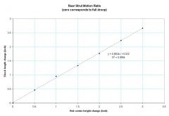
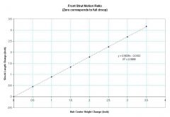
Here are the graphs: As you can see the motion ratios are quite constant (the slope is constant) over the range that I measured.
-
-
-
I'll have to measure that tomorrow (or this weekend). I'm getting ready to go to bed. I have to be back at work at 1 am. I'm on third shift all week until we get Atlantis off the pad.
-
I just came in from the garage. Since I had the car up and the springs removed, I decided to measure the motion ratios of the front and rear suspension. I did this as follows: 1. Jack and level the car. 2. Remove springs and reinstall strut. 3. Let strut go to full droop and perform following measurements. ---a. Measure from ground to center of hub. ---b. Measure length of shock tube to line on bump stop. 4. Jack wheel up 1/2 and perform following measurements: ---a. Measure from ground to center of hub. ---b. Measure length of shock tube to line on bump stop. 5. Repeat step 4 seven times to get measurements through the range of travel. 6. Graph shock measurements versus hub measurements. 7. Fit regression line and get slope (inches of shock travel/inch of hub travel). For the rear, I came up with a motion ratio of 0.882. For the front, I came up with a motion ratio of 0.904. The suspension ratios at the center of the tire contact patch are related to the ratio at the center of the hub by a constant that is equal to one for wheels that have a zero offset. My suspension is modified as follows: Front: Stock length lower control arms (fitted with inboard spherical bearings) Shortened strut to fit Koni 8610-1149 insert. Lower Control arm pivot point moved up 3/4" and out 1/4". Top of strut tower moved back ~3/4" 1" bump steer spacer Ground Control camber plates. Rear: Custom rear control arm adjusted 1/4" longer than stock Eccentric camber bushings adjusted equally to maximum negative camber. Shortened strut to fit Koni 8610-1437race insert. Ground Control camber plates. Though my suspension is fairly heavily modified, none of the modifications will have a huge affect on the motion ratios.
-
Thanks for the replies. I think I am going to do two things: First, I think I'll lower the car an additional 1/2" to gain some more rear droop travel. Second, I'm going to install some stiffer springs. I've been wanting to do this for a while, but I needed to wait until I had some decent rear struts. Currently, I have 250 lb/in springs in the rear and 200 lb/in in the front with a 1" front sway bar and no rear sway bar. I now have 8610-1149 front struts and 8610-1437race rear struts. I just need to decide which springs to get. I plan to go through all the math and pick the springs as suggested in chapter 16 of Milliken's RCVD.
-
I have completed sectioning my rear struts and installing the Koni 8610-1437race inserts. I ended up taking 2.25" out of the housing and installing a 1.5" spacer below the insert. At the same time, I got rid of the stock upper spring isolators and installed Ground Control camber plates. I finished putting the car back together on Saturday and discovered that I had virtually no droop travel with the back of the car at 6.5" (measured at horizontal portion at the back of the rocker panel and a 245/45/16 tire). So, to gain some droop travel, I lowered the car so that the back of the rocker panel is at 5.625" an the front is at 5.25". I now have 1" of droop travel without me in the car. The control arms are almost level with the ground and the front angle upward to the wheel. I was a little concerned that this would not be enough, but not so concerned that it prevented me from running in an autocross on Sunday;). I was a bit afraid that I might experience a snap oversteer situation, but much to my surprise that was far from the case. The car performed very well. In fact, it went pretty much anywhere that I pointed it. While I am very happy with how the car performed in an autocross, I have lingering concerns that the limited droop travel might be insufficient for a track event. How much droop travel are you track gurus running?
-
Yet another Rear control arm design
74_5.0L_Z replied to tholt's topic in Brakes, Wheels, Suspension and Chassis
Putting the rod end in double shear would definitely be a whole bunch simpler. I dig simple. -
Yet another Rear control arm design
74_5.0L_Z replied to tholt's topic in Brakes, Wheels, Suspension and Chassis
The rod ends that I'm using in my current rear control arms are Aurora XAM10-T which have a 3/4" shank and a 5/8" ball. For axial loads they are rated at ~40,000 lb. Aurora suggests that the rod ends are good for 10% of that in the orientation we use them. I'm toying with the idea of using a ball joint on the A-arm portion. To do so I would have to modify the rear strut. We'll see... -
Yet another Rear control arm design
74_5.0L_Z replied to tholt's topic in Brakes, Wheels, Suspension and Chassis
The angle between the strut housing and the end link for the sway bar would be less than 20 degrees. If the sway bar were applying 200 lbs of force at its end, the force applied perpendicular to the strut (bending force) will be equal to 200 lb x sin (20 degrees) = 68 lbs. This torque would be proportional to the amount of roll and would only be present in turns. Mounting sway bar end linnk will cause a bending moment in the strut. -
Yet another Rear control arm design
74_5.0L_Z replied to tholt's topic in Brakes, Wheels, Suspension and Chassis
The strut tube is behind the axle shaft. So without modifying the strut, the rear rod end is below (but inboard of) the strut tube. I like having the fixed point on the A-arm below the strut tube so that adjustment to toe will have a minimal affect on camber. So, the spacing between the rod ends has not changed. -
Yet another Rear control arm design
74_5.0L_Z replied to tholt's topic in Brakes, Wheels, Suspension and Chassis
I like the first example because it is simpler and uses fewer rod ends. It is exactly what I envision. As far as the anti-sway bar goes, I don't use a rear sway bar. If I did, I would rather attach upward to the strut housing rather than down to the control arm. I assume that the connection between the toe link and A-arm is a spherical bearing and that it is free to rotate. -
Yet another Rear control arm design
74_5.0L_Z replied to tholt's topic in Brakes, Wheels, Suspension and Chassis
You will not get any binding as long as the spindle pin is parallel to the axis of control arm rotation. So lengthening the track shouldn't be a problem. The issue that might occur is having enough adjustment at the top of the strut to compensate for camber. Adding 50 mm per side to the length of your lower control arms will give you about 6.5 degees of negative camber. I don't think my Ground Control camber plates can compensate for that. This does sound like the topic for a new thread. -
My car is not set-up as a drag car. I mostly autocross it, but I have had it to the drag strip. My best so far is a 12.42 @ 113mph. The engine is from a 1989 mustang. The engine came from a junkyard and the only thing that I have done are some bolt-on modifications. Edelbrock 60379 Performer 5.0 Heads Cobra Intake 1.7 FMS roller rocker arms Crower 15511 cam 24 lb/hr injectors C & L 73 mm Mass Air Meter 65 mm Throttle body I have never touched the bottom end and I know that it has at least 150,000 miles on it. All that being said, I have a 331 stroker on the engine stand just waiting for me to finish it.
-
Yet another Rear control arm design
74_5.0L_Z replied to tholt's topic in Brakes, Wheels, Suspension and Chassis
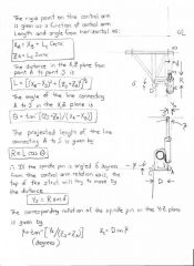
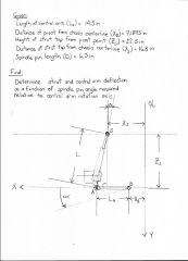
Tholt, Your conclusion is what I came up with. The magnitude of the deflection is less than I assumed (that's why I did the calculations and spreadsheet). What the spreadsheet also says is that if the control arm cannot flex, the top of the strut will try to deflect 0.026" for a 0.3 degree toe in condition (0.3 degrees is equivalent to 1/8" toe in and a 24" tire). In reality, the strut will be much stiffer than the control arm, so a majority of the deflection will occur in the control arm. The ratio of the torsional stiffness of the control arm to strut will determine force applied to by the control arm to the strut. If the control arm has a torsional stiffness of 1000 ft-lb/degree, a significant side load will be applied to the strut. If the control arm has zero torsional stiffness(as in an A-arm toe link), then no side load is applied to the strut. As you observed, much (but not all) of the strut deflection due to splindle pin angle can be mitigated by careful alignment of the strut. By this I mean that after a toe adjustment, the strut must be shimmed forward or aft to minimize the deflection. As an example, if the toe is set at 0.3 degrees, the top of the strut will move backward 0.026" with the control arm horizontal, and will vary from 0.021" to 0.026" to 0.021" as the strut goes through its full range of motion. 0.026" is equivalent to 0.070 degrees of control arm twist. So given 1000 ft-lb/degree, the torque will be 0.070 x 1000 = 70 ft-lbs. The bearings inside the strut are approximately 16" above the connection to the control arm, so the side load on the bearings will be approximately 70 ft-lb*(12in/ft)/16in=52.5 lbs. Given the same conditions as listed above: If the strut is shimmed backward 0.021" after toe alignment, the variation can reduced to 0 to 0.005 to 0 as the strut goes through its range of motion. The maximum twist on the control arm is reduced to 0.0118 degrees and the strut side load will be reduced to 0.0118/0.070 x 52.5 = 8.85 lbs. Now assume the worst case with the toe is set at 0.3 degrees as above. Instead of shimming the control arm to correct direction, assume that the strut has an intial misalignment of 0.125". The twist in the control arm increases to 0.48 degrees. The side load on the strut now increases to 0.480/0.070 x 52.5 = 360 lbs:shock:. If we must use the H-arm strut lower control arm, we need to be really careful to shim the strut forward or back to minimize the control arm deflection and strut side loads. These problems completely go away with the A-arm toe lnk type lower control arm. Dan -
-
-
Yet another Rear control arm design
74_5.0L_Z replied to tholt's topic in Brakes, Wheels, Suspension and Chassis
Having the toe rod in compression won't be a problem as long as it is not too slender. I believe that the correct location of the hard point is below the strut tube. Having it there decouples the camber and toe adjustment. One thing that I want to explore is the length of the toe rod and its affect on roll steer. I have the fixture fom the construction of my old control arms. It will not be hard to modify it to make some of these. I expect to have some made within a month. -
Yet another Rear control arm design
74_5.0L_Z replied to tholt's topic in Brakes, Wheels, Suspension and Chassis
Jon, That is the exact design that I had in mind. -
Yet another Rear control arm design
74_5.0L_Z replied to tholt's topic in Brakes, Wheels, Suspension and Chassis
Jon, If you read my post immediately above, then you will see that we had the same eureka moment. Dude, get out of my head:mrgreen: