74_5.0L_Z
-
Posts
1209 -
Joined
-
Last visited
-
Days Won
34
Content Type
Profiles
Forums
Blogs
Events
Gallery
Downloads
Store
Everything posted by 74_5.0L_Z
-
A very good question. My engine is installed centered between the frame rails, and it works. However, if I were to do it again, I would offset the engine towards the passenger side. This would provide the following two benefits: First, it would allow for better U-joint angles on the driveshaft, and better centering of the shifter in the factory hole. Second, it will make corner balancing the car easier. If you look at my post regarding my corner weights, you will see that the right front is very light compared to the left front. Also the left side percentage is about 51.6%. Offsetting the engine 1/2" - 3/4" to the right will help with both of these issues. The difficulty will be in finding block hugger headers that allow this engine position.
-
I just finished repainting my car, and as part of the process I removed the windshield and hatch glass. Removal was simple. I just cut through the rubber close to the glass, and then I just lifted the glass out. Then I finished removing the weatherstrip. After painting, I reinstalled the glass with new weatherstrip. I (like you guys) was a little concerned about the installation. I even called some local windshield people and got a quote for them to come install the windshield and rear glass. They wanted about $200.00. I am really cheap and a bit of a do-it-your-selfer, so I opted to try it myself. There are several write-ups on this site and others, but here is what I did: First, install the weatherstrip on the glass. This is pretty easy to do with the glass out of the car. Second, get some quarter inch diameter rope (~ 12 feet) and push it into the outer channel of the weatherstrip all the way around the periphery of the glass. I configured the rope so that the two ends of the rope met at the bottom center of the glass. The rope will act to open the outer channel of the weatherstrip so that you can get the seal started onto the lip on the body. Third, set the glass in body opening with the tails of the rope on the inside of the car. Try to set it such that the bottom edge of the gasket is close to engaging the lip of the body. Fourth, get a helper to apply light pressure to the outside of the windshield and to prevent the outer lip of the seal from getting pinched. In my case, my wife was on the outside using a plastic spreader to guide the outer lip of the seal. Step four is performed by slowly pulling the end of the rope from the inside and guiding the inner lip of the seal over the lip of the body. Work slowly and evenly. Pull one end of the rope and then the other. When both ends of the rope have been pulled around to the center top, the windshield will be fully installed. Use the plastic spreader to guide the edges as required. The process sounds complicated, but was actually quite simple. I installed both the windshield and rear hatch glass in less than one hour with only minimal assistance from my wife. In my case, I did not reinstall the metal strips in the new weather strip. I don't like the way that they look, so I left them out. Some have said that the metal trim helps with the sealing function of the gasket. It probably does, but I have not noticed any leaks. In my case, the car only gets wet when I wash it.
-
Great video and one of my favorite Rush tunes. I've seen them on every tour since Moving Pictures. With a name like Cygnusx1, I should have known that you were a fellow Rush fan.
-

Chassis Setup (corner weights)
74_5.0L_Z replied to 74_5.0L_Z's topic in Brakes, Wheels, Suspension and Chassis
I am resurrecting this thread because I have made some significant changes to the car, and thought some might be interested in the changes in weight and balance. My original numbers were as follows(for full detail see the first post on this thread) Here are the results with 16 gallons of fuel and me (190LBs) in the car: LF = 648 Lb RF = 607 Lb LR = 751 Lb RR = 710 Lb. Total = 2716 Lb These were are my percentages: (LF + RF)/ Total = (648 + 607)/2716 X 100%= 46.2 percent on the front 53.8 % on the rear. (LF + RF)/ Total = (648 + 751)/2716 X 100% = 51.5 % on left and 48.5% on right. my diagonals were equal ie.. (LF + RR) = (RF + LR) -> (648 + 710) = (607 +751) = 1358. Since that time I have done the following: Redone the body (SubtleZ with customized air dam and hood). Changed from a 16 gallon RCI polyethelene tank to a 12 gallon ATL cell. The old tank was centered, and the new tank is offest to the right. Replaced the old lead acid battery with an Odyssey lightweight battery. Moved battery forward and down from behind rear passenger side wheel well to behind passenger seat. After all that, the final results were: LF = 669 Lb RF = 626 Lb LR = 714 Lb RR = 668 Lb. Total = 2677 Lb These were are my percentages: (LF + RF)/ Total = (669 + 626)/2677 X 100%= 48.4 percent on the front 51.6 % on the rear. (RF + RR)/ Total = (626 + 668)/2677 X 100% = 51.7 % on left and 48.3% on right. my diagonals were nearly equal ie.. (LF + RR) = (669 + 668)= 1337 (RF + LR) = (714 +626) = 1340. -
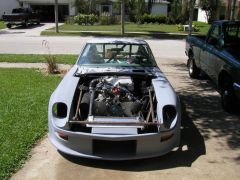
 I have done almost everything myself. The exceptions are the final welding and the final application of the paint. In the build-up of the chassis, I spent 8 months designing, fitting, fixturing, and tack welding the cage. After all the prep, it took the welder 8 hours to finish the welding. For the paint, I spent 3 years doing the body work (including all the fiberglass, the initial priming and blocking). The painter applied the final primer, color and clear in three weeks. I have spent the entire time as his assistant during the process. For some things, I believe persistence is sufficient. For others, actual skill is required. Thus, I do all of the grunt work preparations, and let professionals perform the skilled tasks. In the end, I get the best of both worlds. In performing the grunt work, I save most of the labor cost but still get a professional final result. Don't get me wrong, I intend to learn to weld. I didn't want to learn on my chromoloy roll cage. I intend to learn to paint, but I didn't want to take the chance of wasting $1000 dollars of raw materials. So to answer your question: Yes I did, and No I didn't do the work myself. It all depends on your definition.
 -
74_5.0L_Z shamelessly emulates Terry Oxendales Hood
74_5.0L_Z replied to 74_5.0L_Z's topic in Body Kits & Paint
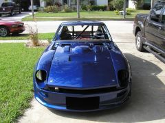
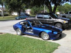
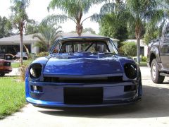
Thanks for the compliments. After three years of work, they mean alot. The color is from a 1997 Acura NSX: Monte Carlo Blue Pearl Metallic. The paint system that was used was BASF Base Coat/Clear Coat. I am in the process of putting the car back together. I'll have some more photos in a few days. -
74_5.0L_Z shamelessly emulates Terry Oxendales Hood
74_5.0L_Z replied to 74_5.0L_Z's topic in Body Kits & Paint
A little more progress:
-
-
-
-
See page 62 for pilot bushing removal. http://books.google.com/books?id=1TFNJyxjMucC&pg=PA62&lpg=PA62&dq=ford+pilot+bushing+removal+grease&source=web&ots=dX6DpicsjM&sig=mS0syVTO9WERQTTdWyQO7oQXH-c#PPA1,M1
-
This is a very well timed thread. My car goes into the spray booth this weekend, and I plan to install my windshield and hatch glass in the next few weeks. My question is: Will the weatherstrip around the windows seal if you delete the chrome trim? I am not a big fan of it and would rather delete it altogether.
-
I just finished installing the SubtleZ kit, and I had similar needs. Here is what I did To build thickness in some areas: I ground away the gelcoat. I mixed West Systems Epoxy 105resin/205 hardener with West systems 403 chopped glass fibers. This is mixed to a consistency of cake icing and spread like body filler. Let it cure and then sand to shape. Then re-skim with a mixture of the Epoxy and West Systems 406 Colloidal Silica (finer texture). And then finish with Evercoat's metal glaze. The mixture of 403 and resin yields a strong hard (but textured) surface. The mixture of 406 and resin yields a finer texture but less strength, and the metal glaze yields a perfect surface. The good thing about using the resin chopped glass as a filler is that it has the same strength and flexibility as the base fiberglass.
-
74_5.0L_Z shamelessly emulates Terry Oxendales Hood
74_5.0L_Z replied to 74_5.0L_Z's topic in Body Kits & Paint
Careless, I'm sorry if you took me seriously. I meant it as a joke. I realize full well that I open myself to criticism when I post my progress. Further, I appreciate and accept the criticism. I was not being defensive and I apologize for giving that impression. -
74_5.0L_Z shamelessly emulates Terry Oxendales Hood
74_5.0L_Z replied to 74_5.0L_Z's topic in Body Kits & Paint
Careless, You are entitled to your opinion, and quite frankly the vents are not my favorite feature of the car. I prefer them to the stock type vents. Oh, next time I want your opinion, Ill beat it out of you:twak:. Take care, Dan -
74_5.0L_Z shamelessly emulates Terry Oxendales Hood
74_5.0L_Z replied to 74_5.0L_Z's topic in Body Kits & Paint
The entire car (including the vents that are apparently such an eyesore) will be painted by the end of August. The car will be painted Monte Carlo Pearl Blue metallic. I am also planning a ghost stripe that starts in the air dam opening and continues out of the opening in the hood. The stripe will then fade into the hood. -
I'm sorry, but what the heck are you doing driving around with cracked fuel lines. Replace the fuel line and filter. Check the oil level in the carbs and top as necessary with marvel mystery oil.
-
-
74_5.0L_Z shamelessly emulates Terry Oxendales Hood
74_5.0L_Z replied to 74_5.0L_Z's topic in Body Kits & Paint
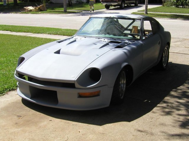
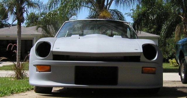
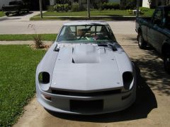
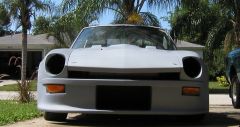
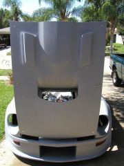
After a couple of months of work, I finally have the front end in primer. I think you will be able to see what the final product will look like. I hope to get this thing in a paint shop really soon.
-

-
-
-
-
I have 245/45/16 Hoosier A3S04 tires on my 16x8 wheels. They were an extremely tight fit under the stock fenders. They fit the wheel very well, but they are a canterlevered design. The car now has the SubtleZ body kit, and I am in the market for some 15x10 or 15x9.5" wheels so that I can run the new 275/35/15 form Hoosier.
-
Look at these links. They contain some really good info pertaining to the driveshaft parts, pieces, and build-up. http://forums.hybridz.org/showthread.php?t=86748&highlight=Neapco http://forums.hybridz.org/showthread.php?t=65652&highlight=Neapco http://forums.hybridz.org/showthread.php?t=75332&highlight=U-joint Pay special attention to the topic of U-joint alignment as discussed by PPARASKA. If you do not have correct alignment of the U joints, you will experience some bad vibration issues.