Dan_Austin
-
Posts
223 -
Joined
-
Last visited
-
Days Won
2
Content Type
Profiles
Forums
Blogs
Events
Gallery
Downloads
Store
Everything posted by Dan_Austin
-
Wheel Show! Post your pics of you wheels
Dan_Austin replied to k3werra's topic in Brakes, Wheels, Suspension and Chassis
Morbias, do you have links to those sizes being produced? That size would be better that the +04, but I have found no US sites listing them or even the possibility of them. I think I saw an Australian site with 17X8 -5, but that seemed to be conjecture about a new size and not anything Rota had committed to. -
Wheel Show! Post your pics of you wheels
Dan_Austin replied to k3werra's topic in Brakes, Wheels, Suspension and Chassis
Where are you gents finding the RKR? I am spitting distance from a couple of Rota distributors, and their inventories either show the RKR in 15" only, or the 17X8.5 4x114.3 +04 in royal silver only. -
You don't want to use that disc if the car is to be street driven, it is an unsprung four puck race. You can, but it will be grabby and harsh. As for ebay clutches, some are excellent, and some might be junk. Without knowing more about your car/engine, it is impractical to try to recommend anything specific, well except that the disc pictured is a poor choice for regular street driving.
-
Most medium to large (16~24oz) cups fit nice an tight in the ashtray as Joe mentions. If you remove the ashtray insert you can place 44oz supersize cups, is they have the reduced bottom to fit standard cup holders. Bottles get stuffed between the seat and console.
-
The naughty word filter seems to be stuck in overdrive. I've seen a few posts with harmless words partially redacted and after a bit of head scratching I realised that the redacted part was usually a word that would make a seven year old giggle. Example of a rotory engine- wankel
-
The Magnecor wires are great, but if you plug them into non-resister plugs you lose quite a bit of the benefit. Seems too obvious to overlook, which is likely why it is sometimes missed. At idle, unless you are running sequential injection your best idle will be on the rich side. The 440cc injectors and resolution in the MS1 are likely not helping you, if it runs well off idle through high load and tracks your AFR targets, then you might want to upgrade to have better control of your injectors. Oh, and exercise extreme care when moving the injector power source. If you have injectors powered when the ECU is not, you can end up with a engine full of fuel.
-
The sense wire is now connected, and I think it did help deliver the death blow. On the other hand the battery was a store brand generic I bought five years ago that was plagued with an underperforming ZX alternator for years. Its time had come, and was on my list, I just wish I had replaced it before I had to walk the 1.5 miles to the parts store caring the old battery to be tested and back carrying the replacement. If the lamp was not connected the alternator would not get excited and not charge at lower RPMs. She actually suggested the full time charge full charge, but most of her customers are building ridiculous stereo & lighting systems.
-
I replaced the externally regulated alternator for an internally regulated one four years ago using the AtlanticZ write-up, so no photos of that. That leaves four wires on the alternator, the charge and ground leads are self explanitory. The new alternator connector has embossed labeling (PLIS or PLFS), with only the L and S leads used. Connect the top of the T connector to the S lead and the L to the leg of the T. The wires on my T connector has discolored to the point that they look the same, so a photo of them would not help much.
-
I can look up the part number for the alternaotr, but finding it by make and model will likely be easier. The turnbuckle and pulley do not have numbers on them. The pulley is just a standard Delco (GM) v-belt, which a decent shop should have on hand. The turnbuckle was a 3/8 X 7.75" OSH special. One small issue to watch for is the battery lug is low and on the inside, putting it fairly close to the lower radiator hose. It cleared by enough not to make me worry, but worth checking. I almost had to retract my positive review today, having major charging issues, but instead is seems a decent alternator can quickly finish off a battery on its last legs.
-
-
-
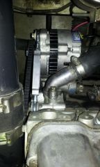
From the album: A-Place-For-My-Stuff
-
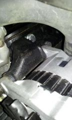
From the album: A-Place-For-My-Stuff
-
The shop owner did swap the pulley. I went with the large GM pulley, which is similar in diameter to the Nissan. A small GM pulley would have been about 18% faster, but she did not have one in stock. At idle the e-fans would pull the system with the previous alternator down to 11.9V, now it hovers around 13.1, both values taken from the ECU voltage reading and logs. I did not check the lights and other accessories, as the the fans were the biggest draw. And this is at a 750 RPM idle, by 800 RPM voltage is back up to 13.6, so it is a shame the small GM pulley was not available. The correct pins are the S and L (leg of the T). The shop owner recommended not connecting the sense lead, so I have it taped off for the moment, but can connect it if desired.
-
I did not snap any as the alternator was dimensionally identical to the 280ZX unit it replaced and the turnbuckle tip was covered in the CS144/AD244 install thread. I can take a couple later tonight and add them to the thread.
-
I've been putting off upgrading my alternator since installing a megasquirt this summer, but the end of daylight savings time has also put an end to my procastination. I called a local rebuilder to pick up a 95A Maxima alternator, since the parts stores in this area will not swap pulleys anymore. The shop owner said she was not a fan of the Maxima unit, and suggested a Delco CS130 off an 88-90 Eagle Premeir/Dodge Monaco. It turns out this is a dual foot unit with the mount lugs at 6 &12 like the Nissan unit, and factory rated at 105A and has a lower activation RPM compared to the Maxima alternator. The one I picked up was tested and confirmed to max out at a 117A. The unit required minor wiring tweaks, and slight massaging of the upper bracket, but no major cutting. I skipped the bracket massage and picked up a small turnbuckle at a hardware store, making this a straight bolt in project.
-
Your ending value should be 100%. If you have it set to 100% at 160 degrees and the WUE indecator does not turn off, I would first suspect the CLT is not calibrated for your sensor and check to see what TS reported for a temp and compare it to either the dash guage (if you trust it). It does not need to be 100% in agreement,but should be close.
-
motomanmike- WUE of 0 means inject no fuel, so you are getting the expected results. The value is expressed in percent.AND MULTIPLIED against the warmed up pulse width. 100% = 1.00, and means no enrichment. (PW * 1.00 = PW) 0% = 0.00 and means not fuel at all. (PW * 0.00 = 0) The terminology is occassional confusing, with a normal reaction to set values to '0' when we want to represent nothing, but that is not what is needed for ASE or WUE. Jacob80- You may be going the wrong direction with the VE cells. If you are over fueling in a particular load it will register as lean on the wideband, and the resulting stubble will feel similar to the seat of your pants. My VE table at 180KPA is about 105 for the 3500 to 4000 RPM range. I am not dyno tuned, so I don't recommend my values, but if adding more fuel in that range does not help, you should consider leaning it out there.
-
This issue is not unique to either eBay or aluminum radiators. Two years ago I bought a copper two core from a national parts chain. The mount holes were not a match horizontally or vertically. I thought they gave me the wrong unit, but the catalog and part number matched. I was able to pry the mounts slightly away from the core to correct the horizontal and drilled new holes to correct the vertical. Of course no offers for rebate and no way for the local store to update the catalog. I'd take the rebate and update the feedback to reflect their desire to make it 'right' and leave a comment about it not being an exact fit.
-
IE9 and this site get along oddly. I have found I need to be in compatibility mode to use the full editor and upload photos, but viewing photos works best when not in compatibility mode. I need a few IE-isms for work, so I live with it, but I can confirm you are not alone.
-
I just realized I never closed the loop on this thread. I actually performed the engine and ecu swap the week of July 4th this year. My company was shut down the 4th to the 6th, so by taking two vacation days I had nine days to complete the project- Saturday 6/30- Drain fluids and remove hoses, wiring and radiator. Also remove console and drop the exhaust. Sunday 7/1- A friend shows up with a hoist and we pull the engine, move the tans to the new engine and drop it all back in. About five hours start to finish. I pull the old harness and ECU while the engine bay is empty. Install the new stub harness and start installing the weatherpack connectors to connect the ECU harness to the stub harnessed I built for the ignition, injectors and sensors. Monday 7/2- Re-install radiator and hoses. Realize I am missing thermostat cover, and start looking for one in parts stores and checking pick-n-pull inventory. No luck, so I finsh the sensor and injector wiring and install the intercooler and piping. Also install dual SPAL 12" fans. Tuesday 7/3- Hit up PNP anyways as the inventory is not always up-to-date. Score a near mint condition cover. Lost three hours in the drive to the yard, the search and the drive back. Install the cover and finish the ignition wiring. Attempt first start. Find a couple of mistakes in main relay and fuel pump relay, kill the weak battery in the process. Wednesday 7/4- Battery has charged over night, wiring appears correct. TunerStudio is reading nominal on all sensors and has clean crank and cam signals. No fire. Pull the distributor cap and count slots in the DIYAutoTune CAS wheel and figure out I am about 140 degrees off in the trigger angle. Reset the value in TS and we have immediate fire. and a loud but steady idle. Thursday and Friday- No progress. My scheduled time with a friends welder keeps getting bumped. Saturday 7/7- Finally get access to my welding friend, but he is not happy with how his welds are tuning out, to he gives me a quick lesson and I end up welding up my 3" exhaust as my first project., from vband on the downpipe, to O2 bung all the way back to the tailpipe. Pick up the peices and head back home to install them. Perform my first hot valve lash and look for signs I buggered something up. Sunday 7/8- Drive around the block a few times to let VEAL start on the tune. Copious white smoke is noticed, leading to concern, then I recall the excess of protective oil in the mandrel bends. By the 3rd loop around the block there is no more smoke. I drove the car for about a week with no muffler, then installed a short Dynomax stainless straight-through design. I spent a couple weeks running VEAL on the 30 minute ride to work and way home, with a few freeway jaunts thrown in for variety, then I manually smoothed out the VE table. The ignition table is based on tables found here and a bit of experimentation. The only issue to date has been one blown fuel injector fuse that was slightly undersized. It worked fine for six weeks until a spirited pull through 1st and 2nd did it in. All said this was a fun project and completely worth the time it took to prepare.
-
My grid was also about 90% flaked off, so I used a razor to clean the rest. The stick kits include new bus bars that need (should be) used to connect to the new grids. The manufacturer suggested that using the factory bus would lower resistance to the point that the grid would not generate enough heat. 1. Scrap off old grid, but leave the bus on the sides (or top & bottom if 240Z) 2. Carefully lay down the new grid lines leaving 3~4 inches extra on each side 3. Place the bus bars over top of the origninal bus and new grid lines. Make sure to leave at least 3/16ths of an inch between the bar and the seal or the trim caps will not fit. 4. Fold the extra length of grin lines over the bus bar, this gives direct contact of the glueless surfaces 5. Install the trim caps The ground lead on this kit is on the bottom of the grid, so I just made a small jumper and connected the ground to one of the hatch strut bolts
-
I used a Frost Fighter complete kit that included a new grid and new bus bars. The new grid was spaced differently that the factory grid, and the factory grid could completely scraped off, so I cut the new grid into individual strips and then carefully overlaid each strip over the original grid lines. The glue on the bus bars was not very impressive, but I have had no issues with the grid itself. The install was done with the hatch removed and a friend shining a light through the glass so I could perfectly align the grid. Being anal about the alignment the project still only took about 90 minutes to complete.
-
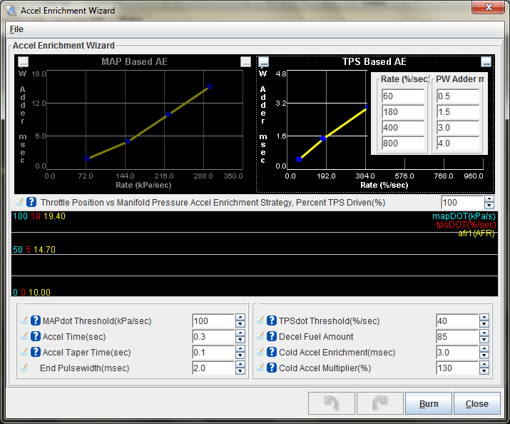
Hesitation when lightly pressing the accelarator after a complete stop
Dan_Austin replied to 2s2mad's topic in MegaSquirt
Cygnus you are the man! Your post got me thinking that my stumble might not be the lean miss I was focused on. I paided closer attention to my cruise pulsewidths, and realized that my gently tweaked AE map was way too much. I had been concentrating on getting the trigger points set and had not given enough thought to the amount of fuel to be added. I ended up reducing each amount by 75% and now have absolutely no stumble at all. I may end up further trimming the larger pw addrs, and then ponder x-tau...