inline6
-
Posts
483 -
Joined
-
Last visited
-
Days Won
7
Content Type
Profiles
Forums
Blogs
Events
Gallery
Downloads
Store
Everything posted by inline6
-

FS5W71B - Item that might be overlooked on rebuild often?
inline6 replied to inline6's topic in Drivetrain
Hmmm. Interesting. Yeah, I looked all over the internet and couldn't find a part number listing for a FS5W71B. But, I wish I hadn't paid $14 for mine (I actually bought two), before I knew about the $4 ones. G -
New Cam and Rockers - odd looking at 500+ miles
inline6 replied to inline6's topic in Nissan L6 Forum
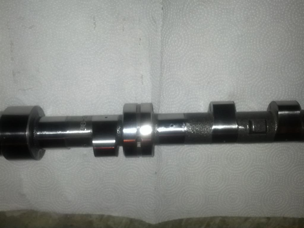
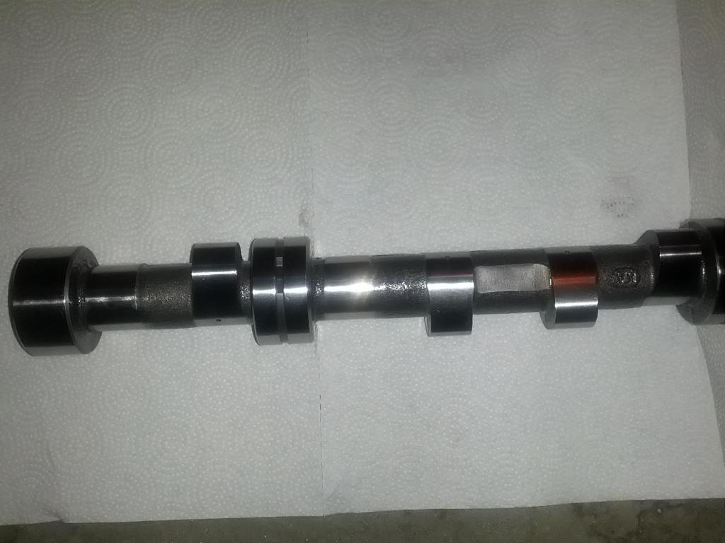
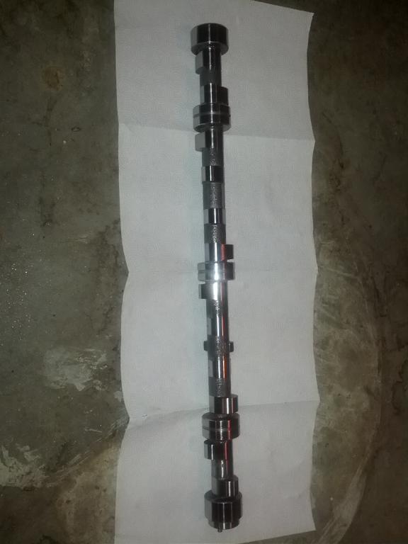
The new cam came in. Oil holes are in interesting locations... Many are in close proximity to the center of the base circle. Some are closer to the opening ramp. And 2 and 11 are just after the closing ramp. Sheesh. Can no one get that right? Was going to work on installing it tonight, but unfortunately there is no rear oil galley plug. Going to have to take it to a machine shop to get it drilled and tapped for a 3/8" NPT. There are a couple of Datsun shops around this area (north Atlanta), right? Garrett
-
FS5W71B - Item that might be overlooked on rebuild often?
inline6 replied to inline6's topic in Drivetrain
Here is the one I got. It appears to be the right OD and ID, but it is 1/8th of an inch shorter than stock. And it only has cutouts/flutes on one side of it. Xnke, were the one's you sourced like mine? Also, stock length or a little shorter? And, mine was $14 plus shipping... instead of what... $3 from Cobra? Garrett
-
FS5W71B - Item that might be overlooked on rebuild often?
inline6 replied to inline6's topic in Drivetrain
Is this the part you are speaking of? The picture is different than the factory... No cut outs or flutes for transmission oil to lube the yoke. Were the ones you got like the part pictured, and if so, how have they worked for you? -
FS5W71B - Item that might be overlooked on rebuild often?
inline6 replied to inline6's topic in Drivetrain
Oh, right. I actually thought at one point along the way that either or both of those were the issue. When I started looking into the problem seriously (a few of months ago now) I did replace those first (the seal and the o-ring on the shift shaft) but I still have the leak. The shifter shaft and top of tail housing is dry - in this case, the fluid is coming out of the rear seal location for sure. The deflection of the driveshaft which appears to visibly allow a separation of the yoke tube to the oil seal lip is my primary indicator at this point. Garrett -
FS5W71B - Item that might be overlooked on rebuild often?
inline6 replied to inline6's topic in Drivetrain
I found this today. http://www.manualtransmissionpart.com/FS5W71-Bushings-Washers.html I placed an order for one, I'll report back when it comes in whether it is the right part. -
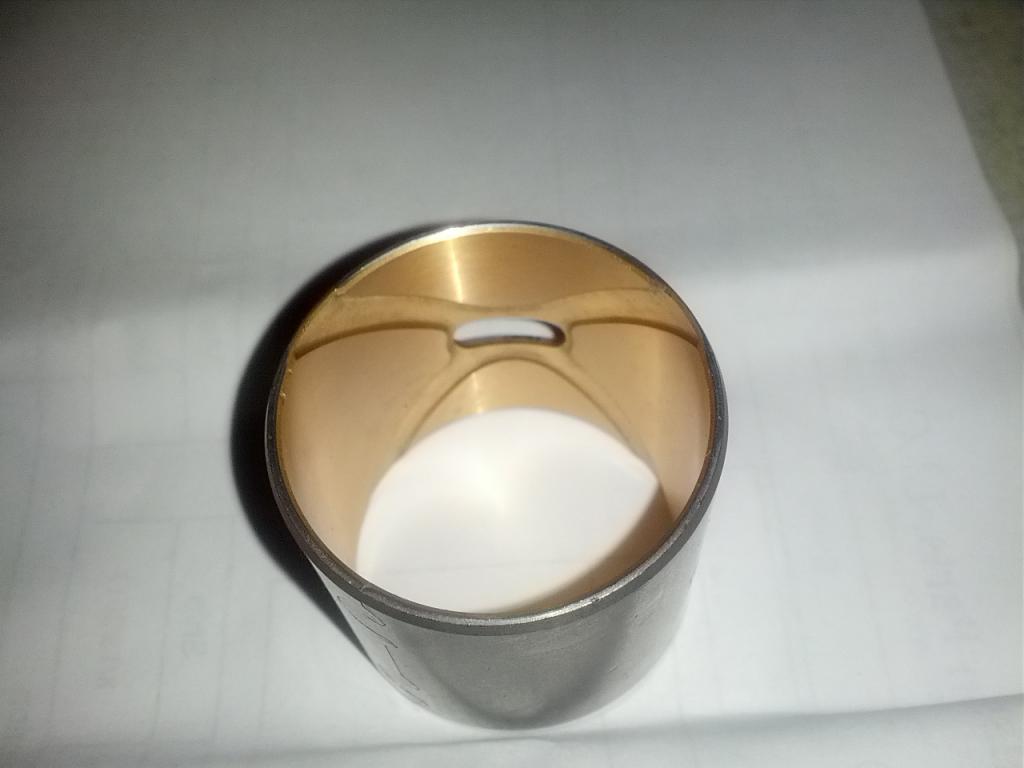
I rebuilt my late model 280ZX transmission a few years back. But, even with a new rear seal, I had a slight leak there. I don't recall if it was there before I rebuilt the trans or only after... I've driven the car rarely in the last several years, primarily a couple of track events, so the slight leak coming from the rear transmission seal was an annoyance, but not something I had to deal with on a daily basis. At first, I thought I damaged the new seal I put in when I rebuilt the transmission. But, I replaced that with another new one (which seemed to help briefly) but I noticed after the next track event, I still had some leakage. I began to suspect that my driveshaft yoke was too small in diameter. I bought it many years ago from Inland Empire Driveline. Even though I never had an issue in running it for years, I thought maybe it was machined to like the smaller end of acceptable tolerance range, and maybe it had worn some over the years, allowing fluid to start leaking. With the car back on the road recently I noticed that after every drive, it was leaking noticeably. I decided to devote some time to finding the issue. I pulled the driveshaft out to measure the OD of the yoke and compare that to a spare factory driveshaft yoke. I measured both with calipers and was surprised to see that they were the same measurement. Ruling out an undersized yoke as the problem, I re-installed the driveshaft and pushed upwards on the driveshaft yoke. I could see noticeable deflection in that direction and it appeared that the oil seal lip came out of contact with the OD of the yoke tube. Pulling down, I could see a rather large amount of deflection as well. I have a spare FS5W71B, so I pulled the rear seal and looked at what was behind. Here are a couple of pics: There is a sleeve which is press fit into the tail section of the transmission case. This one is showing some wear, but I suspect the one that is in the car right now is much worse. I'm guessing that with the amount of movement the transmission output shaft/driveshaft yoke is being allowed, it not only allows the seal lips to come out of contact with the yoke tube, but I am eating up rear main seals quicker... With these transmissions (of this vintage) likely to have lots of miles on them at this point, I wanted to make everyone aware of what I found. Also, anyone have any ideas for best way to repair? I can't find the sleeve on the microfiche... It doesn't look to be a part I can buy new from Nissan. Garrett
-
New Cam and Rockers - odd looking at 500+ miles
inline6 replied to inline6's topic in Nissan L6 Forum
Megacycle was able to source it. They initially said they would have to try to track one down and in a conversation weeks later (they were waiting for info from the guy that used to run Integral Cams to locate the master), said they had a few on hand. Oil lubrication hole location was discussed in this thread earlier. Just wanted to mention that I asked Megacycle to drill them in more optimal locations, but the cam blank came with those already drilled. -
New Cam and Rockers - odd looking at 500+ miles
inline6 replied to inline6's topic in Nissan L6 Forum
Megacycle found that they had the master for my cam all along. New cam has been manufactured and is in route to me. -
New Cam and Rockers - odd looking at 500+ miles
inline6 replied to inline6's topic in Nissan L6 Forum
Just a little update... The two people I've talked to at MegacycleCams seem to be really knowledgeable. Both were familiar with Estas blanks. They told me that I shouldn't have nitrided the Estas blank because they are "chill cast" as is, which makes them harder than other cam blanks. We discussed how I came to nitride that cam. We talked about CWC blanks which they said are definitely "softer". Additionally, we discussed the oil I am using - Mobile One. They said that Mobile One is a poor choice for my application - "a rubbing surface rocker". In fact, they said they see more cam failures from use of Mobile One than any other oil, but I'm betting a lot of that has to do with it's percent of market share - it clearly has a large part of the full synthetic market. They brought up the lack of Zinc in modern oils being a problem especially in my application and basically, to keep it simple, said I should use RedLine or Motul... though they mentioned a couple of other oils that are also good for rubbing surface rocker applications. Unfortunately, they don't have a 100% of the masters from Integral Cams - they don't have the one for my cam. They are in contact with the former owner of that business and believe they can get the cam profile info - the design specifications from him in the next week or two. They plan on making a new master. This should be good news for anyone that would like to have this "Kinetic Sunbelt" cam grind. They talked about spray welding on the lobes to create the hardest lobe possible, but I don't want to go into uncharted territory again. I told them that I just want them to use an Estas blank, and I'll forego the nitriding this time. Time will tell if they can make it happen for me. Additionally, I believe I have tracked down the valve springs that are used with the cam. "1W901" was on the Kinetic Sunbelt invoice. A little searching on the internet brought me to this Nissan part number: 13203-1W901 Looks like my springs may be outer valve springs from what looks to be like several different VG engines. They are $4.89 each at NissanPartsZone.com. I will check that out further at some point down the road, probably by buying one and checking to see if the specs on it match what we put in my engine. G -
New Cam and Rockers - odd looking at 500+ miles
inline6 replied to inline6's topic in Nissan L6 Forum
As I said, Kinetic is no longer sourcing these cams. Did some searching... Found the paperwork that came with the cam. The cam manufacturer was Integral Cams. The are no longer in business. However, I found online that Megacycle Cams bought all of their "masters" - this means they should have what they need to make me another one. Called Megacycle today, and they confirmed this. So, now I'm going to pull the cam out of the head and send both that cam and a stock cam to them along with all the documentation I have on the "z-car l-series datsun E30 race cam #2" as it is named. I'd like to get another cam made from an Estas core, but might get a regrind from the stock cam. We'll see. -
I do.
-
New Cam and Rockers - odd looking at 500+ miles
inline6 replied to inline6's topic in Nissan L6 Forum
Indeed. It clearly didn't matter for the stock valve train, but it becomes an issue at some point with higher lift cams, higher lb valve springs, etc. -
New Cam and Rockers - odd looking at 500+ miles
inline6 replied to inline6's topic in Nissan L6 Forum
Checked with Sunbelt about a replacement cam. They are "no longer sourcing these cams". I pulled out my paperwork and see that the cam was manufactured by Integral Cams, who have since gone out of business. Found a post online that said http://www.megacyclecams.com bought all the cam designs. I guess I'll give them a call on Monday, but I was thinking, I have the old cam and some pretty good documentation on it... Would it be possible to send it off to someone and get back an identical replacement? Garrett -
New Cam and Rockers - odd looking at 500+ miles
inline6 replied to inline6's topic in Nissan L6 Forum
A few things to point out in relation to what you said: You know, sometimes it is better not to listen to all of the internet talk. Yes, I try to verify info from more than one "good source" before I believe it whenever possible. Anyone who has spent a lot of time on the hybridz site or others for that matter can discern who those people generally are. The Schnider cams are not a good buy, due to the metal and how it was hardened. This is still debatable, as many have had and continue to have success with Schneider cams. The first cam I bought for my car, which I never installed was probably a Schneider - I bought it off of someone on eBay. It was made from a CWC cam blank. I discovered all the discussion about those blanks (many cam grinders use them - not just Schneider) after purchasing it but before I put it in the head. I decided to send that cam off to Comp Cams for nitriding as a precautionary measure - some insurance for not having a problem, if you will. That cam had other issues, and I ended up not using it. Incidentally, I don't think anyone (Schneider, Isky, Sunbelt, etc.) is hardening these l-series cams. I think they just grind/re-grind, and then parkerize. Looks like to me the cam was still to soft, the rocker pads looked good, a little worn due to the soft metal coming off of the cam, but for the most part they looked good. A cam that has gone through an ion nitriding process such as mine will have a harder surface than one that has not. So, my cam isn't too soft. The problem is elsewhere. You guys are more then welcome to try NEW things, but it is going to more then likely cost you, and a repair and replacement of the cam and rockers. You mentioned you had SINGLE springs with a .550 lift cam, if what I read was correct. ONLY SUNBELT that I know of runs the SINGLE spring configuration on their cams, I think from memory the seat pressure is about 75-80psi on the seat. Have fun with RPM's over 7K. Yes, I agree - Sunbelt is also the only one I know running a single spring configuration. My cam is a Sunbelt cam. The valve springs are Sunbelt as well. Seat pressure at installed height according to the supplied info is supposed to be 54 lbf. As installed in my car, it came out to 56 lbf. Red line on the valve train is 7700 RPM - I am running titanium retainers. This stuff is not rocket science guys, go with the people who have BLAZED the trail for you and forget about all the new cool stuff, I really don't consider what Sunbelt did to be new at this point. As far as I can tell, this cam and spring setup was developed many years ago (I can find mention of their cam development in the forums on hybridz from 2005) and it has been proven. They may not have been one of the original trail blazers but they have a good reputation - I base this on what I can see from the previously mentioned "good sources" of information on these forums saying nothing but good things about them, and, I don't know if he is still racing a 240z, but I think they were the engine builders for the multi-national title winning Greg Ira? Also, you mentioned the oil holes in the cam, Don't even think about drilling a oil hole on the lobe where the ramp starts. The hole was placed right where it needs to be. Some of the holes are not where they should be - period. Long story, but I'll make it short. Had a 490/290 in a Datsun 510. It was put together by Malvern racing. The springs were Nissan Comp. I ran it for a short period of time and had no issues, but coming back from college late one night, I spend some extended amount of time at high rpm and I wiped one lobe and one rocker due to lack of lubrication. The engine builder for Malvern Racing took the cam to his varsol tank and pushed fluid through it to watch the flow. The lobe that wiped happened to have its oil hole on the trailing side of the lobe, just after the closing ramp - basically 180 degrees away from the best place for it. With the new cam (same grind) we made one change only. Using that existing hole as a pilot, he drilled all the way through it to the other side, so a hole would be in front of the opening ramp. I never had another problem and I drove the hell out of that 510.. I do understand the concept of doing what has worked... following the recommendations of experts who know what works and what doesn't. I now believe the nitriding of the Sunbelt cam was a mistake, one that happened because I was hard headed. Following are direct quotes from emails with Sunbelt back in late 2009 when I was working with them to get the cam: "The cam blanks used by your cam grinder have never been "CWC" blanks. Though Kinetic has tried Nitriding and Parkerizing in the past, the fine polish finish on the lobes has worked best for lobe durability. I asked Jim to confirm the cam grinder used the same came blank (Estas) as usual." And my response: "...as it stands now, I would feel more comfortable with a Nitride treatment, but I don't want to ruin the fine finish on the lobes if that is beneficial. You guys are the experts, just tell me which way I should go. The couple week turn around won't be a problem for me because the car is down for the winter. How should we proceed?" And finally: "I spoke to our cam guy about the Ion Nitride process that they use and he says the finish is a lot better than the old nitride process..." and " talked to Jim, go ahead and send us the cam and we'll get it nitrided. He said he really doesn't think it's necessary but he understands the peace of mind thing." So, my recommendation to those who read through this later is this: If you are considering nitriding your L-series cam, don't. It isn't necessary and may cause you the problem I encountered. You must get good lubrication to your L-series cam before the initial start of a new/worked on engine. Do whatever it takes. -
New Cam and Rockers - odd looking at 500+ miles
inline6 replied to inline6's topic in Nissan L6 Forum
LOL! Yeah, well, for the $800 dollar replacement cost, I should get something besides a lump of cast iron, but I won't. -
New Cam and Rockers - odd looking at 500+ miles
inline6 replied to inline6's topic in Nissan L6 Forum
The only reason I did it is at the time I was buying the cam (several years ago) was that there was a rash of discussions about the soft "cwc" blanks that it seemed every cam grinder was using. I just thought that nitriding the cam would eliminate that issue. Of course, the cam I ended up wasn't a cwc. -
New Cam and Rockers - odd looking at 500+ miles
inline6 replied to inline6's topic in Nissan L6 Forum
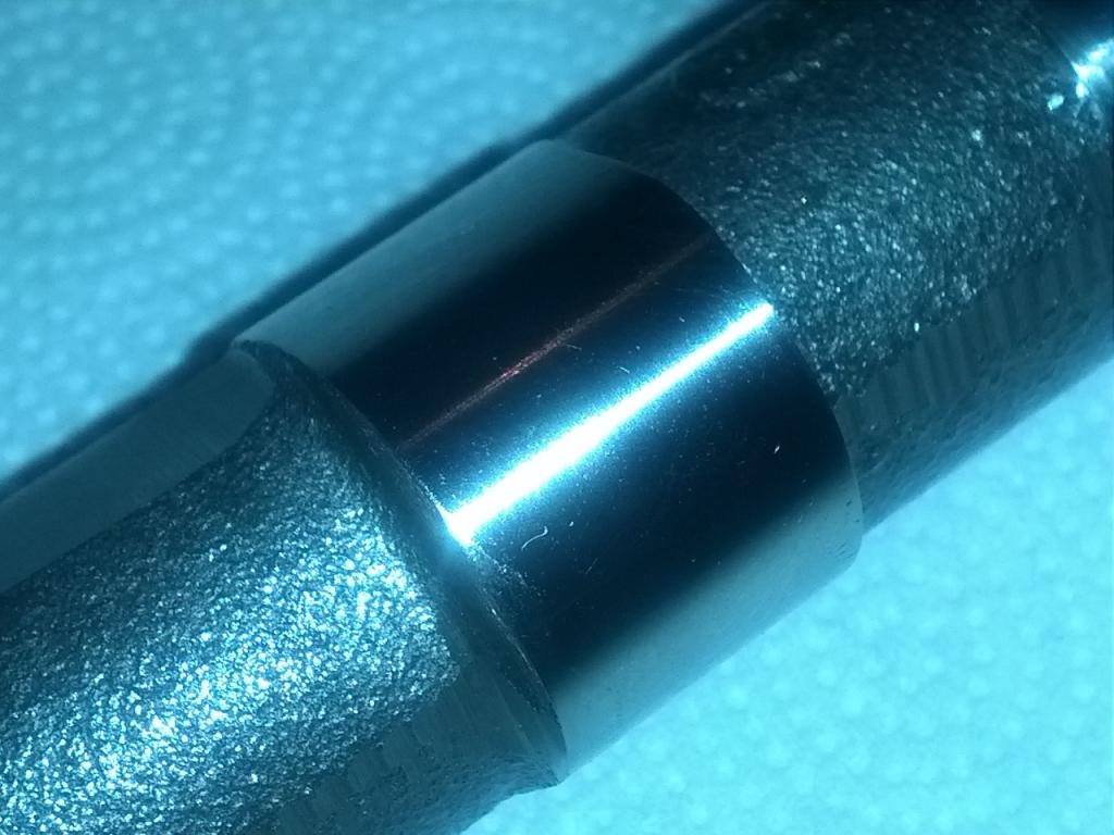
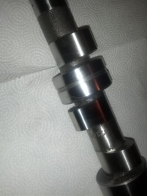
Since I am waiting on the shortened Z31T axles, I went ahead and pulled the valve cover off to check the cam. After not even 15 minutes of running at low rpm just sitting in the garage, the lobes are showing ominous signs... In fact one of them has started ejecting its surface just like before. At this point, I believe nitriding is the cause. I read in a couple of places about nitriding cams causing the surface to be "too hard" or I guess having the surface made brittle. So, the theory is that the impact, or perhaps the heating and cooling, or something else about this application, is causing the surface to "craze" or fracture and then fall off in tiny, tiny bits. So, the cam is trash. -
Oh, I actually don't need to have welding or straightening done - I was using search to try to find some info about Kinetic Sunbelt and this thread came up in the results. Good to know though. If I had to redo my engine, I'd want to go with welding the head rather than milling a ton off like I did last time.
-
Hey John, Do you know where Jim is these days? I called Kinetic today and they said he is no longer there. Garrett
-
New Cam and Rockers - odd looking at 500+ miles
inline6 replied to inline6's topic in Nissan L6 Forum
I got the resurfaced rockers and the cam back from DeltaCamshafts Friday. The rockers looked really nice. I bought them new, and the rocker pads had some very minor pitting which I didn't care for. The same ones which I got back from DC looked much better than when new. I installed the cam today (put lots of assembly lube on) and fired the engine up. A very different experience than the first time, when I couldn't get it to start, this time it fired right up and of course, had oil pressure immediately. I'll run it for a couple hundred miles and then take the valve cover off and have a look-see. Can't do that though until I get the shortened Z31 T CV axles back from the Driveshaft Shop. G -
Here is mine. It is a Magnaflow stainless tip. It started out at 18" in length. I cut off what I needed, and sold the remainder of it on ebay. http://forums.hybridz.org/index.php?app=core&module=attach§ion=attach&attach_rel_module=post&attach_id=45861 http://forums.hybridz.org/index.php?app=core&module=attach§ion=attach&attach_rel_module=post&attach_id=45860
-
Which Mikuni's, 40's or 44's? What is the history on them? New... old... bought used, unknown history? Do you have a timing light, and can you see what the timing is set at? If it was me, I'd look up the timing value to use for that distributor (use the value for whichever datsun it came off of - 280zx? I just don't know which car it came from) and set it at that. And, I'd check and reset the carb float levels. Typically, you can remove the tops of the carburetors without ruining the gaskets. Then go about setting the float heights - the distance between the top surface of the floats (two per carb) and the underside of the carb cover. Note, that each one of them needs to be checked. If one is lower than the other, you have to bend them,like grabbing a wish bone of a chicken and moving one up and the other down... until they are nice and level compared to each other. Then set the distance between the tops of the floats and the bottom of the cover at 12.0 to 12.5 mm. I cut a thin strip of metal and grind/sand to the precise length. Then hold that with needle nose pliers between the float and the chamber to check/adjust the height. Typically you hold the carb cover at 90 degrees compared to the floor when checking, so that the floats don't have gravity pulling them down away from the needle valve or pushing hard against the needle valve. You want just enough pressure from the float arm against the needle valve to depress the pin it contacts, but not to open the valve itself (it has a noticeable stopping point, right before the valve itself opens). There are a couple of ways to adjust the heights, but I prefer to just bend the tab on the float arm... where it contacts the needle valve. It only needs very slight movement there to effect the needle valve closing point. Are you familiar with the jets in the Mikuni's? Do you have other sizes on hand?
-
Group buy threshold has been met. Please delete this post. We only need one more person to get the discount. Here is the thread with info: http://forums.hybridz.org/topic/112204-order-for-shorter-z31-turbo-axles-from-the-driveshaft-shop/
-
New Cam and Rockers - odd looking at 500+ miles
inline6 replied to inline6's topic in Nissan L6 Forum
That's like three people who have done this. I'm like Tony, I could never figure out how people were doing this with the worm gear on the crank... but I understand now how this could be done if you make a special long shaft (no gear on it) that just drives the oil pump.