inline6
-
Posts
483 -
Joined
-
Last visited
-
Days Won
7
Content Type
Profiles
Forums
Blogs
Events
Gallery
Downloads
Store
Everything posted by inline6
-
I started to order it from RockAuto, but decided shipping and handling or whatever was a bit much for the one part. Am going to find a couple of other items I need and get it coming. Also had the thought to do some measuring. I mean, I can measure how much M/C rod moves for each inch of pedal movement, and the same for the slave. I should be able to take the FSM clutch pedal stroke (8" from floor to clutch pedal stop) and knowing the diameters of the stock M/C and slave, calculate volume displacement for each. Then, I might be able to figure out what size m/c and slave would be required to work with that same stroke to get full disengagement.
-
To be clear, I don't like the situation. I'm just describing it. I'd like to come up with a solution so there is enough fluid being passed to give the slave the travel that needs to occur for full clutch disc disengagement... with stock clutch pedal stroke. There is always this option - lol
-
The spring diaphragm mechanism on the pressure plate pushes everything (the t/o bearing, sleeve, fork, and clutch slave piston) back. It all settles... with the c/s piston in a position which is pretty well bottomed out in the slave. I confirmed this by removing the two bolts that mount the slave and trying to compress the piston more. It doesn't go very much further at all... maybe a 1/16th of an inch. Right now, on my car, the piston on the slave is "out" enough that of its total 21.8 mm of travel (again, with the way everything is set in my car right now), 6.6 mm of it is gone. So the remaining 15.2 is available. If I were to crack open the bleeder on the slave, then the piston in the slave would again retract fully. And given everything else in my clutch system is not changed, once I tighten the bleed screw again, I'd have a not functioning clutch because I'd only have 15.2 mm of travel available. In order to get more, I'd have to back of the little bump stop that holds the pedal at ~ the same height as the brake pedal again. That would retract the piston in the clutch m/c so that once pushed forward again, I could again pick up the 6.6 mm that was lost when the bleeder screw at the slave got opened. I could again set the clutch pedal height using the little rubber bumper pad, but I'd be right back where I am as the car sits - 6.6 mm of a total of 21.8 mm of stroke having occurred at the slave already. I don't think he is using mechanical means. If you push in the clutch pedal somewhat, so that the slave is engaged and moves the clutch fork, and you then lock the position (with the little rubber pad that contacts the pedal), you've pre-loaded the clutch... with a hydraulic system.
-
Did some measuring today. I backed the rubber bump stop away from the clutch arm completely. I set the clutch m/c rod so that the clutch engagement off the floor felt right - not too high off the floor, not to low. My clutch pedal was roughly 1.5 to 2 inches higher than the brake pedal which is at FSM height. I then set the clutch pedal so it was hard against the clutch pedal stop on the floor. Then I measured the clutch fork distance from the slave. After writing that number down, I released the clutch pedal completely and measured the the clutch fork distance from the slave again. I calculate that I have 21.8 mm of total throw at the slave right now, but... I then set the rubber bump stop against the clutch arm to bring the clutch pedal to approximately the same height as the brake pedal. And I took another measurement at the slave. With the clutch pedal height reduced, I now have 15.2 mm of travel at the slave. That means the slave has been activated by 6.6 mm... with the clutch pedal now in the new static position. I drove the car, and shifts are not bad. I also don't notice any clutch slipping. But with 6.6 mm of travel already occurring (this is net of any slop in the clutch pedal linkage by the way) the t/o bearing is clearly "running" at all times, and the pressure plate spring fingers are somewhat depressed. This is not right enough for me...
-
Nice. Plus one for buying a $9 dollar 11/16ths slave and giving it a shot. Regarding the clevis, I read where one person modified theirs just by drilling the threaded hole out of the clevis they had and welding a nut with thread that matches the rod to it. If you have a welder, that may expedite your project. A lock nut is still needed, of course. 7/8" is "a lot" bigger than 5/8" when it comes to these master cylinders, isn't it? My car is already beastly to drive in so many ways after various mods... adding another by switching to a heavy clutch pedal doesn't appeal to me.
-
But, doesn't pre-loading of the T/O mean the pressure plate spring fingers are loaded also? And so the PP isn't clamping with full available force? I can see how that would still work, but one really doesn't know how much slippage is occurring, right? A suitable compromise... sure, but I would prefer to have properly engineered/functioning parts. I'm curious how much of your "solve" of high rpm shifts is your mods. vs. more travel, by the way. If I get enough travel, I may find out.
-
Found another zcar.com thread with info about clutch pedal height that is interesting - Tony again... go figure. The FSM says to use the threaded rod on the clutch master cylinder to set the clutch pedal to the correct height off the floor. But Tony says (in post #10): "Pedal height is pretty much irrespective of the adjustment---the bumper on the screw should adjust that...the clevis simply sets where the piston is within the cylinder itself." Now, that is interesting. As I stated above, I set the clutch pedal height at 8" by threading the clutch master cyl. threaded rod in until the pedal was 8" off the floor. I then set the rubber bumper on the screw so it was snug against the clutch pedal arm. Setting it in this fashion made it so I could not shift into any gear with the engine on. Separately, when I bolted the slave cyl. to the transmission, I had to compress the slave cyl. rod. Fully compressed, the slave will bolt to the tranny with no issues. The piston in the slave is pretty well bottomed out. Based on what Tony said, I decided to test something. I loosened the lock nut on the rubber stopper and backed it as far away from the pedal as possible. Then I loosened the lock nut on the clutch master cyl. rod and screwed that rod out of the clevis until the pedal was again in the position where the clutch became functional. My clutch pedal is now at like more than 9 inches off the floor - more than an inch higher than the brake pedal. Then... I again set the rubber bumper to hold the clutch pedal at 8" off the floor. But, as I did so I watched the slave cylinder. And, as I moved the clutch pedal down from 9+ inches to 8", I saw that the slave cylinder rod moved, which "pre-loaded" the throw out bearing on the PP spring fingers. So... given what Tony said: "Pedal height is pretty much irrespective of the adjustment---the bumper on the screw should adjust that...the clevis simply sets where the piston is within the cylinder itself", and what I see happening on my car from the aforementioned steps that I took, then what gives? My conclusion is that the only way he could be right is if one additional thing is done in my scenario with my car. If it is true that pedal height can be irrespective of the adjustment... that I can set that simply with the rubber bumper on the screw... then the only way to alleviate the slave cylinder movement I am experiencing is if I crack open the bleed circuit after I have set the clutch for proper operation with the clutch master cylinder threaded rod. But won't that just return the slave rod back to the original start position and won't I lose all of that travel (that I had)? I'll give it a shot, but seriously, I am coming to the conclusion that the 5/8" MC and 3/4" slave don't have the stroke to get this job done.
-
I just verified that stock 1983 Datsun 280ZX non-turbo has a 5/8" clutch master and 3/4" slave... same as what I have now. Just found this post (#8 in thread) from Tony where he points out that there is a common problem with clutch master cylinders that have rods that are too short. He mentions aftermarket... I don't think mine is aftermarket because it is a Nabco, so maybe it isn't just an aftermarket issue. His post #9 is also interesting... I have been wondering why my poor shifting seemed to have gotten worse recently when it had been workable for many years. The new clutch disc actually makes the problem worse because the fingers in the spring diaphragm actually move away from the throw out bearing a bit more. As a clutch disc wears the finger move closer to the T/O bearing. And finally, in that post, the original poster (OP) states that they solved their problem with a slave from a 1988 Pathfinder. I looked around for some images and see that the Luk one at RockAuto has numbers on the side like the original equipment (OE) ones. It looks to me like it says 11/16. Ok, now I see some of the descriptions of the others say 11/16". Same amount of volume of fluid being forced (MC) into a smaller container (slave) would cause the slave piston to move further... and man are those Pathfinder slaves cheap!
-
I tend to be rather wordy, so I am editing and putting the questions up front: With a 240 mm clutch upgrade and a late style ZX gearbox, are the stock clutch master cylinder and stock slave cylinder suitable to achieve enough travel for full disengagement of the clutch disc, without pre-loading the throw out bearing? If so, can suitable travel be achieved with the clutch pedal in the stock position - 8" from the floor? If not, has anyone focused on this issue and come up with a combination of MC and Slave that does work with the clutch pedal at 8"? (End edit) I've never been happy with my clutch since I switched to a late style 280ZX 5 speed eons ago. I messed with pedal height and got it to work ok way back then and drove it for years without any real issues. However, with my new engine which revs higher, I am having a much harder time getting it out of gear and getting it into gear at high revs. Today, I tried setting the clutch pedal height back to stock per the FSM. I set it at 8 inches from the carpet on the floor to the front surface of the rubber foot pad by undoing the lock not on threaded M/C rod and screwing the rod into the clevis more to lower the pedal height. After doing this, I can no longer get the car to shift into gear with the engine running. Clearly the clutch pressure plate spring fingers are not being engaged enough to release the clutch disc. The clutch M/C and slave have been checked for leakage and there is none. System has been bled thoroughly and no air bubbles are coming out. I have visually verified that the rod on the slave is moving the clutch fork. Additionally, I took the slave off the tranny, took out the clutch fork boot, and shined a light up inside the tranny. I tried moving the fork by hand back and forth. In it's natural static position, it seems to me that the throw-out bearing is resting on the pressure plate spring fingers. I can't force the fork (pushing toward back of car) and achieve any movement at all. I can, by putting light force from the back toward the front, get the fork to move some in that direction. That obviously pulls the throw-out bearing/collar away from the pressure plate. My clutch master cylinder is a 5/8 Nabco. It is stock 240z as far as I can tell. My slave cylinder is 3/4" Nabco. Are these suitable, or no? The disc and PP have about 1500 miles on them. They are ClutchMasters 240mm units which are mounted on a Fidanza aluminum flywheel. Through my searching I am aware that there are different T/O bearing collars and that I need to have a stacked height of 92 mm from the flywheel surface to the "wings" on the throw-out collar that the clutch fork rubs against. Is there any way to measure this without take the trans out of the car? Clearly, something isn't optimal. If I raise the clutch pedal about another inch or so higher than the brake pedal by screwing the threaded rod in the clutch M/C out, I can get a functional clutch. As I said before, however, 7000 rpm shifts pretty much don't work - the shift lever resists my efforts to pull out of first... and I can't get into second until the revs drop below 6000. Also, the reverse idler gear is not quite stopped... it is causing a bit of grinding when shifting into reverse even with the clutch pedal firmly against the pedal stop.
-
Indeed, the 37 chokes could be too small. Regarding one change at at time... I have become learned. Separate threads occurred... here is the one that I am most current with. Since I already own a TWM and Electromotive fuel injection setup, spending money on new (or machining of some 34's I already have) chokes is not too likely. The TWM throttle bodies are 45's... with no chokes.
-

Just started playing with Innovate LM-2 on Mikuni 44 2.9L stroker
inline6 replied to inline6's topic in Fuel Delivery
Decided I would try 195 Mains to see what the change in AFR would look like. Obviously, I'd like to lower that hump in the AFR in the 5400-6400 territory if at all possible. So, I figured I see what the 195s would do. It was a pretty substantial change. And, as expected, AFR got richer where I didn't need it to also. I haven't had any luck getting airs to lean out the top in, so I am hesitant to order something bigger than 270's - I don't think it will make a difference. So, now the question is, which of those two plots is better? Should I stick with the 195's, or go back to the 190's.
-
NA 3.1L=>head & camshaft questions. No shortcuts, max
inline6 replied to zredbaron's topic in Nissan L6 Forum
Interesting... I was starting to suspect "reversion" and came across another hybridz post (sometime during the hours and hours of searching/reading) where another member addressed their "bog" issues completely by adjusting the cam timing. My engine builder spec'd out the cam timing with three different settings on my adjustable cam sprocket. One of my recent tuning changes was to retard the cam a touch to see if it improved the wide open throttle (WOT) below 4k situation. Retarding the cam changes intake valve opening and closing times relative to piston position, so it has an impact of the amount of reversion. Ah... so when you pulled off the rocker cover, the number one valve (exhaust) was as pictured: valve keepers missing and valve bent (it looks bent to me...). You mention a rock or a nail... Were you running without an air filter? How about a pic of the number one spark plug? -
NA 3.1L=>head & camshaft questions. No shortcuts, max
inline6 replied to zredbaron's topic in Nissan L6 Forum
It looks like those cnc rockers (that one anyway) has had holes drilled through it... perhaps to decrease weight. I don't see those holes in the earlier pics of them you put in the thread. Am I seeing that right? Did they come that way? Did you pull the valve retainers for that one valve, or were they jettisoned during the failure and that is how you found it? I'm coming up with theories... As an aside, I noticed you said that the engine doesn't deal at all with WOT below 4k RPM. I've been working on tuning in recent weeks and have been chasing after that same issue (if I recall correctly, we have the same cam). Been using a LM2 data logger and making changes one step at a time. A vexing problem has been its inability to deal with WOT in higher gears (3rd, 4th, 5th) and lower RPM's (less than 4k in 3rd - I don't even attempt such a thing in 4th or 5th anymore). I have found a combo that allows full throttle in first without issues and once the revs are up, I'm all good. (Edit: Nice - I just saw your AFR curve... that is the same mountainous beast I am dealing with! ) Still, the Mikuni's (44's) are losing their aura. FI is going to happen sooner rather than later. -
Just started playing with Innovate LM-2 on Mikuni 44 2.9L stroker
inline6 replied to inline6's topic in Fuel Delivery
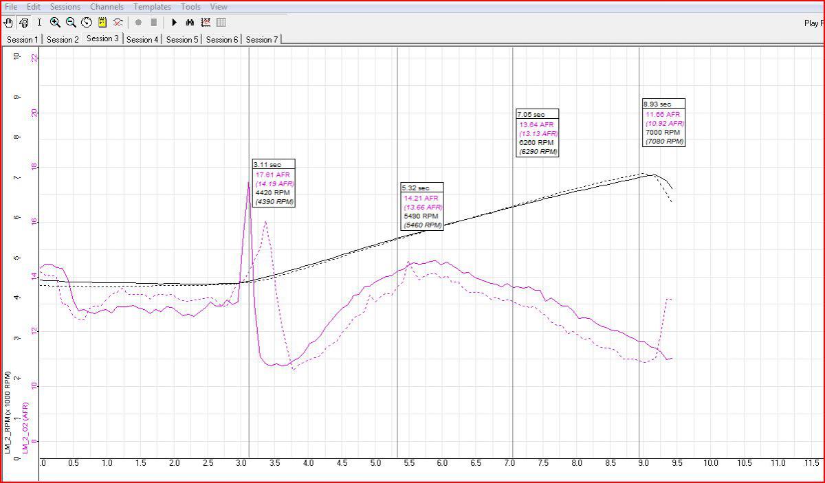
I've been trying to lean out the top end as of late. But, I have found that even substantial size increases has little to no effect in AFR at the high RPM range. For example, here is an AFR vs. RPM plot of the following jet combinations - the dotted line is the run with a 250 air jet: Main 190 Air 250 Pilot 57.5 Pump 50 Choke 37 vs. Air 270 I bought the 270's this past week and tested them this weekend. It seems no matter how high I go, I can't change the AFR at the high end. Here is another plot. This one shows a comparison of a much earlier run when I had 180 Mains and 220 Airs (dotted line), and everything else is the same vs. the latest 190 Mains 270 Airs that are in the car now. This is the problem... I can't get the upper range to lean out. What could be the problem? Are the carbs somehow not getting enough air?
-
NA 3.1L=>head & camshaft questions. No shortcuts, max
inline6 replied to zredbaron's topic in Nissan L6 Forum
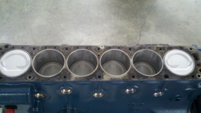
There is some nice art here - thanks for it. Here is the oil pan that mortensen was speaking of. Seriously consider it. I got one not that long ago... I think 4 to 5 weeks is lead time much cheaper than the Kameari one. The shiny "sliver moon" on the right side of my pic indicates exhaust valve to piston contact. My leak down before and after the chain being off a tooth is the same 2 to 5 % across the cylinders. I think I got lucky, but will have to check again after some more miles to know for sure. -
Any updates?
-
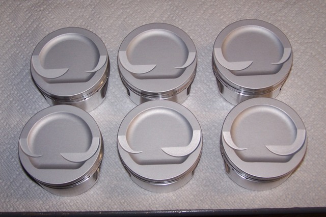
Those look a lot like the JE pistons in my engine.
-
Just thought I'd put this out there. In all of my researching on the forums and elsewhere, I have never come across this value. Honsowetz says 1.5. I've seen several mentions of 1.0 in these forums (which is what the Mikuni Manual shows for 40 phh). The Mikuni Manual does indicate 1 1/8 turns out, however. G
-
NA 3.1L=>head & camshaft questions. No shortcuts, max
inline6 replied to zredbaron's topic in Nissan L6 Forum
On my engine, I believe the Kameari tensioner will allow the chain to loosen enough to slip one tooth on the crankshaft gear sprocket. That happened to me recently (though I pulled the upper tensioner part out completely when this happened). The car wouldn't rev right and the engine was louder. I was thinking that the valve adjustment had gone out of wack, so I tightened up the clearances a couple of thousandths. However, that made the noise worse - so I shut it down. I bought a bore scope and found that the exhaust valves were tapping the pistons. That and recently messing with the tensioner led me to suspect the cam timing was messed up - which is what the problem was. Here is a pic of the bore scope LCD screen: Any changes with the tensioner that might have allowed the chain to slip a tooth? G
-
NA 3.1L=>head & camshaft questions. No shortcuts, max
inline6 replied to zredbaron's topic in Nissan L6 Forum
I've had cars that burned oil in the past. At 500 miles per quart it becomes very noticeable. How much oil was actually left? At several quarts per 100 miles, there really will be a constant smoke screen. I think you can rule burning it out - also, go to rear of the car and check the rear panel... if it was burning it, there is going to be tiny oil droplets all over the entire panel. A leak of some sort is far more likely... to lose that much oil in that brief a period of time. Look under the car from the engine back for evidence of any leakage. That much oil leaking is going to coat some portion of the underside of the car. The coolant system couldn't take on that much oil either. I think the entire capacity is like a little over two gallons... Easy enough to check if there is oil in the coolant. Just drain and examine. I have the kameari chain tensioner. When it is too tight, it does make more noise, but you really can't put any significant load on the engine by having it too tight. Cross that one off. Very sorry that this happened. Do what you can to distract yourself from it... until the emotional part dies down. Don't dwell in it. You'll get it back to where you want it to be. Just watched the video. Are you running an open exhaust? -
Just started playing with Innovate LM-2 on Mikuni 44 2.9L stroker
inline6 replied to inline6's topic in Fuel Delivery
I just rediscovered this suggestion from you last night while reading back through this thread - it helps to have all of this info in one place to see where I have been and to hopefully inform where to go next. I am playing with AFR vs. RPM. Will see if I can get some plots together. -
Just started playing with Innovate LM-2 on Mikuni 44 2.9L stroker
inline6 replied to inline6's topic in Fuel Delivery
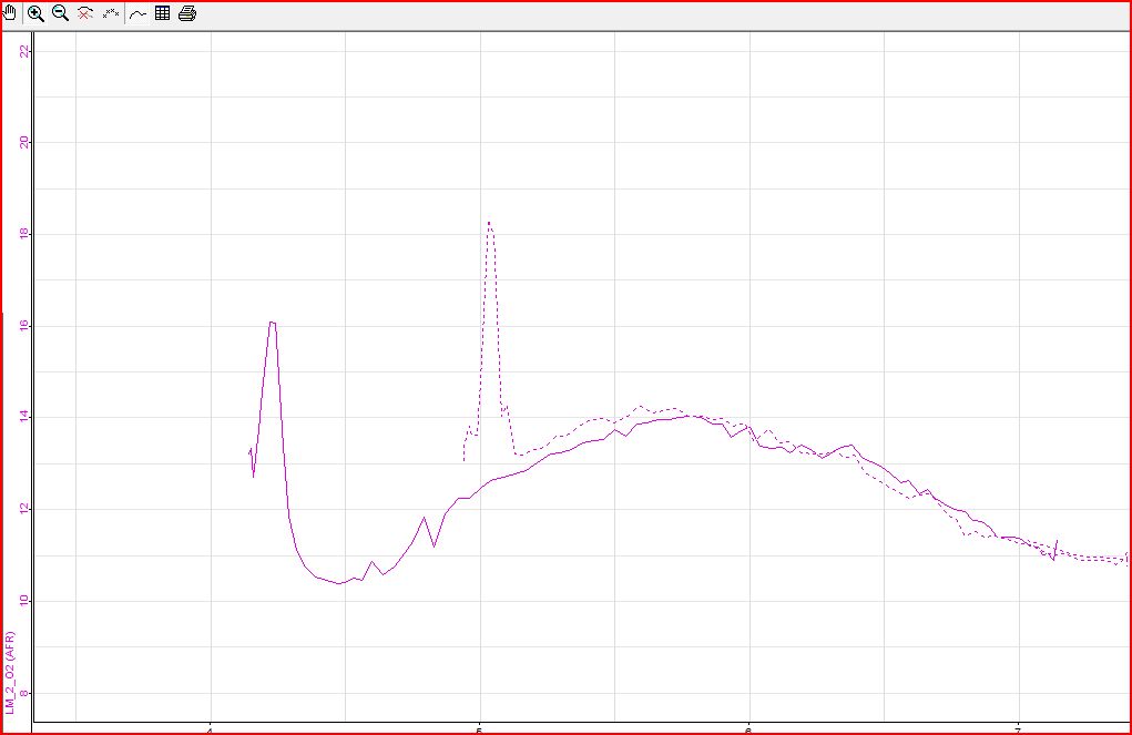
Spent the time to adjust the accelerator pump lever throws to the Mikuni manual spec. - 7.5 mm. They were about 4 to 5 mm prior to doing so. I went out after that change and got new baseline curves. That is the solid line in the plot below. Interestingly, my lean spike at WOT is back now. What I had in the carbs for the baseline: Main 185 Air 250 Pilot 57.5 Pump 50 Choke 37 Also in the plot are the dotted lines which is the change to 190 mains after recording new baselines (no other changes): No matter what jets I throw at this thing, I can't get that hump in the middle hammered down. Stepping up the size of the mains is making the curve richer for the entire RPM test range. While the bump in the middle shrinks, the AFR at the ends - just after WOT and full throttle above 7000, also descends. Combo in the car is now: Main 190 Air 250 Pilot 57.5 Pump 50 Choke 37 I am pretty far outside any other jet combo for Mikuni 44's than I have seen for any other 6 cyl. Z engine. Seems like I have something weird going on... wish I could identify it. Need to start thinking outside the box. Maybe I should revisit my cold air intake system... or maybe I have some weird fuel pressure fluctuations as RPMs change...
-
Since I've been having various issues trying to tune my Mikunis for a new engine, I decided to check my pump lever stroke measurement - this is something that I did not check when I put the carbs on the car. The Mikuni manual clearly shows that the pump lever is supposed to move 7.5 mm when a cotter pin is used in the center of the three holes on the rod - for 44 PHH carbs. With the carbs still on the car, I used my borescope and a piece of stiff wire with the 7.5 mm measurement clearly marked on it. Operating the linkage to full open, I saw the pump lever move about half the 7.5 mm distance. Now, two of my Mikuni carbs were near new when I bought them, and one is obviously a bit older. However, all three of them have about 3-4 mm of stroke instead of the factory spec. The spec being off, especially for the new carbs is really surprising. I can't believe it... and then the older carb was set the same. I even have another rebuilt one laying around, and I checked that one too. It had about 4.5 mm of stroke. Is there a chance that factory manual is incorrect? Anyone else ever gone through the trouble to check their pump lever stroke dimension? I have now pulled each of the three carbs off the car and am proceeding with setting the rod such that the pump lever travel is 7.5 mm when the linkage is operated (using cotter pin in middle hole). I hope I am not making a mistake because its a pain to go through all of this for a misprint.
-
Just started playing with Innovate LM-2 on Mikuni 44 2.9L stroker
inline6 replied to inline6's topic in Fuel Delivery
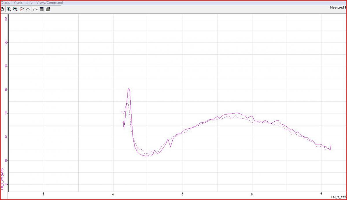
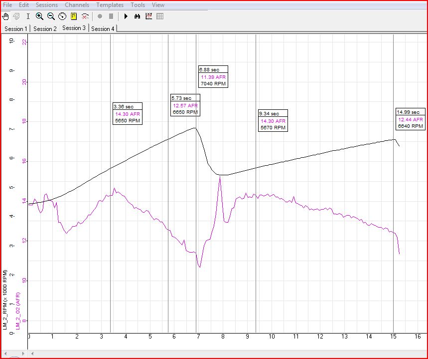
I managed to get a few runs in despite the rain showers. One goal for today was to check to see if tightening down the intake manifold and header nuts changed anything. I saw essentially no change due to that. Next, I discovered that the front carb was being held to the manifold by only the top two nuts. It took me forever scrounging around my boxes of Nissan hardware to find a couple of 8 X 1.0 mm nuts for the carb isolator studs - what an uncommon size! I also changed out the pumps to 50's because I have seen that anything less causes a spike on full open throttle for the tuning runs I have been doing. Here is a comparison of 45's to 50's: The brief "jump" to lean at WOT, is essentially gone with the 50's. This is a run in both 3rd and 4th: It's not exactly easy to see, but the AFR curve is actually very consistent - just compare the same RPM in 3rd vs. 4th. As you can see with the stat markers I have, it doesn't matter what gear, the curve is essentially the same. I've logged a large number or 3rd and 4th gear pulls now, and I have overlayed them and compared the differences. Right now I have this combination in the car: Main 185 Air 250 Pilot 57.5 Pump 50 Choke 37 By looking at 3rd in this chart, all I am dealing with is revealed. Even with many main fuel and air correction jet combinations, the shape of this curve generally does not change. I have low 14's at steady state cruise 3100 RPM in 5th. I have low 13's at steady state 4600 RPM in 3rd. I can snap open the throttle at 4600 RPM in third without a lean spike. The AFR drops very briefly to low 12's, then climbs. It crosses over to the 13's around 5200 RPM. 5800 RPM is often the peak in lean AFR around and is about 14.4. Then AFR turns downward again. I don't see below 13 until about 6500 RPM. AFR keeps marching downward linearly from there until about 7000 RPM - where it hits low 11's. It does pretty much level off right at 11... I have rarely been going much above 7200 for now. Since low 12's for WOT through the power band of this cam is the goal, my next move will be to throw some 190 main jets in. 250 airs are as big as I own at the moment, but it looks like I'm going to need to buy something bigger. 300 airs is the largest size - I am at 250 now. Perhaps I need to start thinking about some larger outer venturis to reduce the "pull" on the aux venturi.
-
Just started playing with Innovate LM-2 on Mikuni 44 2.9L stroker
inline6 replied to inline6's topic in Fuel Delivery
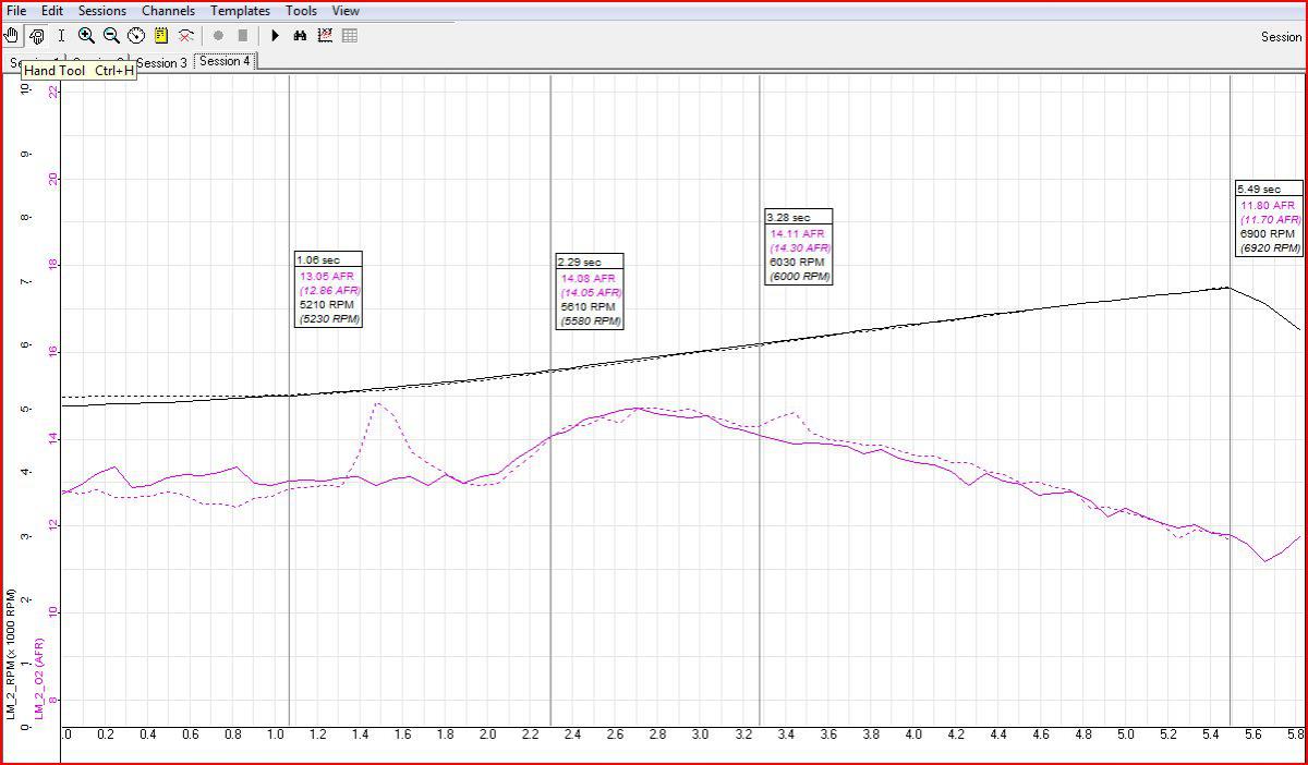
That makes a huge difference. If I squeeze the throttle, AFR on the screen of the LM-2 doesn't go as low, and the engine doesn't misfire. I have to squeeze slower in higher gears vs. lower (4th vs. 3rd specifically - I haven't even tried full throttle in the .745 overdrive in 5th anytime recently). I have to squeeze slower at lower RPMs vs. higher. Anything over around 4500 RPM right now, even in fourth, and I can snap the throttle open and I am ok, meaning I don't get the low to mid 10s and perceived misfire - the AFR still drops into the low 11's initially though. Haven't done that yet. I can put it on the agenda for this weekend. Bummer is I have to travel about 6 miles through stop and go to get to my "test area" on the interstate. I could schedule another dyno session. I've got an R200 4.11 in the car. Here is another plot from when I had the best set up in the car thus far. Because the tune was improved with the change I made for this run, I decided to snap open the throttle at lower RPM in third than I had been doing - to test that issue. I eased off until I was around 4k instead of 5k, and quickly went WOT.