JMortensen
-
Posts
13742 -
Joined
-
Last visited
-
Days Won
68
Content Type
Profiles
Forums
Blogs
Events
Gallery
Downloads
Store
Everything posted by JMortensen
-
The side gears move relative to the little worm gears inside. Underneath them are spring washers. There is another thread where people are complaining about the springs wearing out. If you replaced the spring stack with a solid spacer, or put in a spacer and fewer washers, there would be less movement in the side gears and the axles wouldn't rub on the housing.
-
There is another thread that talks about the springs under the gears. I mentioned in that thread the possibility of installing a solid spacer since the springs wear, but I haven't followed up to see if anyone had done it or had even looked into it yet. Your problem would also be solved by putting a solid spacer in there. Could use a spacer with springs, or without...
-
I think you can pretty clearly see the tube going through the firewall here: http://s160.photobucket.com/albums/t177/psanders240/BSR-260Z-IMSA/?action=view¤t=jeffery-R1-E012.jpg#!oZZ17QQcurrentZZhttp%3A%2F%2Fs160.photobucket.com%2Falbums%2Ft177%2Fpsanders240%2FBSR-260Z-IMSA%2F%3Faction%3Dview%26current%3Djeffery-R1-E022.jpg As to whether it is illegal, depends on the class. For IT, nothing can go through the firewall but they're limited to a 6 point cage IIRC. Other classes have other requirements. Most every class will say that the firewall needs to be sealed, but you can do that with the bars going through the firewall. I had bars in nearly the exact same position and I welded plates on my car to seal the firewall and the cowl as well. Cool pics, thanks!
-

Pics of your Z and 15s - Hunting for tire sizes
JMortensen replied to boro92's topic in Non Tech Board
There are quite a few slicks in 15". I used to run 250/590/15 Yokohama A005s.
-
Having had no experience with the OBX, I will say that the regular Nissan carriers, both the open and the LSD carriers, are really loose compared to what you find on every other vehicle that I've seen worked on or worked on personally. You have to BEAT the ring gear of a Toyota or a Ford 9" onto or off of the carrier. The R200 ring gear just falls off the carrier after you take the bolts out. If the OBX is the same I wouldn't think it is too big an issue. One thing that could be checked is ring gear runout to make sure that it's not on crooked.
-
For those with Lexan windows, mostly the rear window
JMortensen replied to BluDestiny's topic in Miscellaneous Tech
Agreed, lexan scratches if you look at it wrong. I don't have any personal experience with the scratch resistant coatings, so that may be something to check out. It also discolors over time, and exposure to things like Windex are bad news, makes it cloud up. If you're determined to use it and want your car to be watertight, you can put the Lexan into the stock weather stripping. I have a friend who did this on his 510 rear window, worked fine. He had to do some interesting bends on the straps to hold it in, but it wasn't that big a deal. -
The carrier doesn't give you the gear ratio. His question was can he swap the gears from shortnose to longnose to change the ratio, and the answer is no.
-
If you aren't comfortable with EFI, don't use it. Shouldn't be too hard to hit your hp numbers without it. It will make the low speed driveability much better as Tony says, but there is no need to use EFI to get 200 whp, and a 200 whp motor doesn't have to be strung out like a crack ***** to make that kind of power.
-
I've got almost enough parts to put it together, but have been tied down with the diff business for an extended period of time, and now I'm changing the software I use for my other business (www.thepetdoorstore.com), so I figure next year, IF I can actually get out to the shop and work on the thing. At this point that is a big if. I haven't given up though. Aiming at 2250 lbs now, since that is the min weight for XP.
-
OBX Differential Inspection and Installation
JMortensen replied to TrumpetRhapsody's topic in Drivetrain
Anyone consider just putting a solid thick spacer in there to take up the slack? Lots of other helicals aren't preloaded at all and taking the slack out would probably eliminate all the cracking/popping noises under decel. It sounds like once the springs wear down you don't have any preload anyway. -
Strut insert question
JMortensen replied to ComicArtist's topic in Brakes, Wheels, Suspension and Chassis
There is a lot to lowering one of these cars that much and still making it handle. It can be done, but usually isn't. If form is more important than function, then do what you want to get the look you're after. If function is more important, then I suggest you start reading in the BWSC forum, read all the stickies and look for other threads about super low Z cars. The info about potential pitfalls, etc is all laid out already. -
Yes, you can reuse Datsun flywheel bolts, but not after they come loose, so go get some new ones. Red loctite and torque in thirds in a crisscross pattern like you would a lugnut is my way of doing it, I've never had them come loose on me.
-
Strut insert question
JMortensen replied to ComicArtist's topic in Brakes, Wheels, Suspension and Chassis
Kind of. Lots of guys run Bilsteins for VW's for example, and there is a lot of crossover of strut inserts between manufacturers. Read the strut thread in the FAQ and you will see that some of us are running Bilsteins built for Volkswagens, but we need spacers and the correct gland nut. If you're willing to do that kind of checking into it, then yes, you can run a strut insert that fits the tube from another vehicle, but you will need a gland nut to fit and possibly will have to section or make a spacer to fit. -
Nissan Motorsports said the ZXR tail made 370 lbs at 100 mph or something like that, but IMO that number is complete BS. The Hybrid Z windtunnel testing showed 250lbs at 120 mph on the S30, but I think they used a larger tail than the one you have. If you're into function, use it. If the form is too disagreeable for you, don't. It does work though, no doubt about that.
-
Credit to you and Bill for doing that and it's better than nothing, but I think an actual test on a chassis would eliminate the garbage in garbage out problem. Cary was talking about it before, maybe we could goad him into it...
-
But John, how are we determining efficiency? If the car in question is going to run big tires or really stiff springs as seems to be the trend amongst the faster autoxers and road racers lately, it would be nice to try and calculate what is actually needed and then try to hit that stiffness goal. With some testing it could actually be figured out and then maybe we could have an argument that was quantified in some way. There are guidelines for torsional rigidity and spring rates out there, if you google it you can find them. The problem is that right now we're all shooting from the hip, and that is largely because testing torsional rigidity is a real pain in the ass. To continue the SWAGging though, I think you're probably right that reinforcing the rockers alone without any other tie ins to the chassis probably isn't the greatest expenditure of time and effort and just makes the car a bit heavier. However, if the strengthened rockers get tied to the strut towers or a cage then I think it's a lot harder to make the case that it's wasted weight.
-
I looked hard at putting an X underneath but the problem was exhaust clearance. I bought the metal to do it, so if it can be worked out...
-
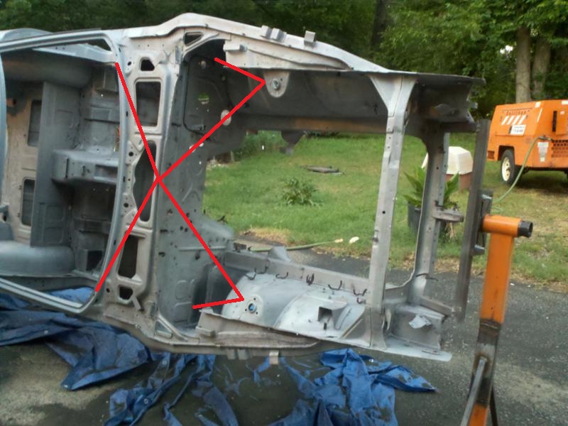
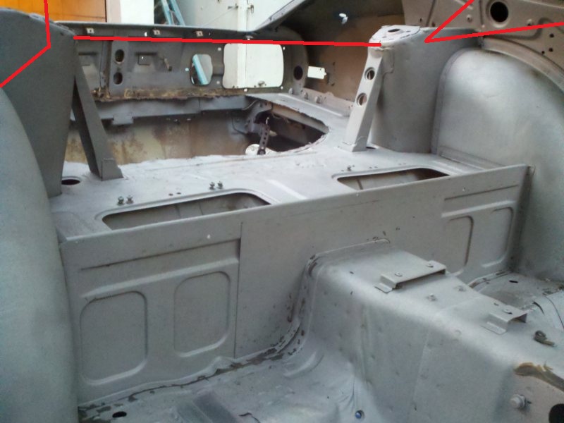
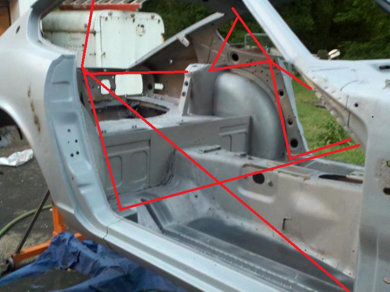
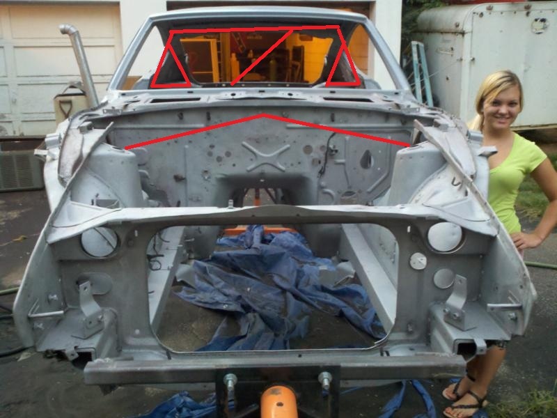
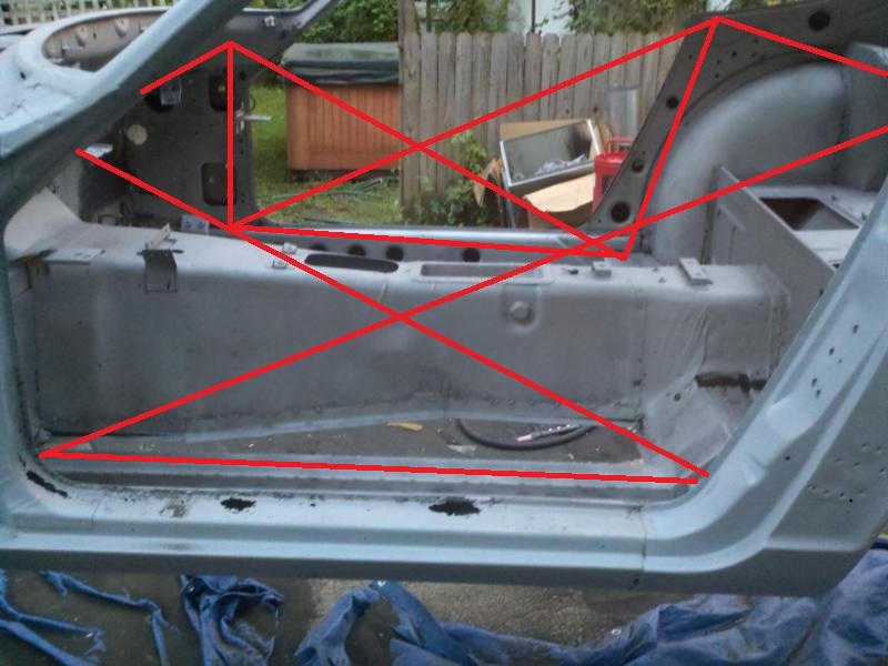
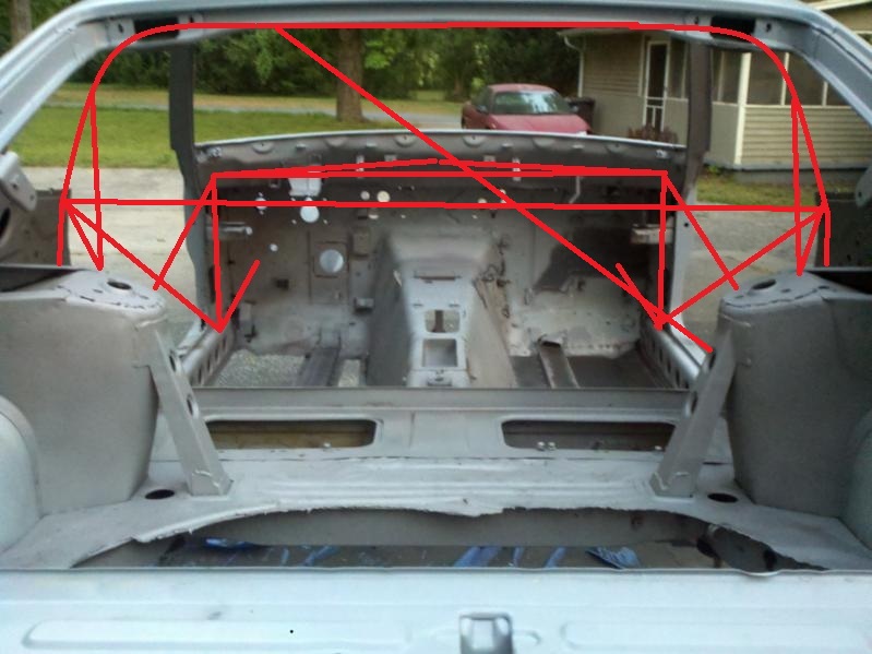
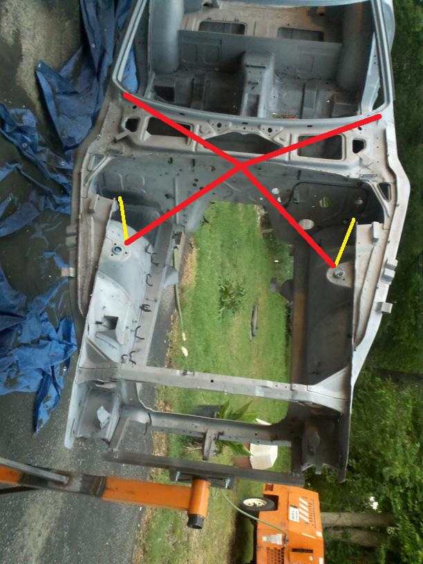
No reason to guess at the weight increase. You can look up weight per linear foot at www.onlinemetals.com. Here is 2x3 .083 wall: http://www.onlinemet...241&top_cat=849 This works out to 2.73 lbs/ft Here is 2x2 .065 wall: http://www.onlinemet...845&top_cat=849 And this is 1.71 lbs/ft EDIT--The rockers are 4'6" from the back to the tip in front, so 9' of metal does both sides. So 15.39 lbs for the square or 24.57lbs for the rectangle, before any plate or weld wire gets in there. There are other thicknesses available, but you just don't need .250" in a Z car, especially when you're attaching it to stuff on the chassis that is much thinner. The problem is that the ties from the rockers to the strut towers are weak. So you can stiffen the rockers, but they aren't attached to the frame rails very well, and the strut towers aren't attached to the rockers very well either. The main structures in front and back are the torque boxes and in the front the vertical area between the torque box and the rocker. Here is a plan for improving the connections here, and gaining a lot of stiffness without a cage. In the front you can run a brace to the TC rod as Joe did, and one straight from the front corner of the rocker to the frame rail perpendicular to the center line. This attaches the frame rail to the TC rod to the rocker in a big triangle. In addition, run one to the upper frame rail outside of the strut (or punch a hole in the fender and run it right to the strut tower a la BRE). Now you have a vertical triangle from the rocker area and the stock vertical support to the front torque box and the upper frame rail/strut tower area. There just isn't a similar simple way to tie the back end together because of the location of the wheels and the strut towers. I would run the tubing in the rockers and then I'd do the X in the back from the strut towers down to the frame rails that Cary, Steve Parmley and I have used. This X is a serious pain in the ass to weld to a cage, but I think it would be a lot easier to weld to the rocker without having to worry about a main hoop. To do this you would probably want to cut out the rear torque box. Probably good to check for seat clearance. I know I didn't lose any seat clearance, but mine attached to the hoop which is considerably higher than the rocker. Then run a good set of strut tower bars front and back, and I think the car would be A LOT stiffer than stock. This is essentially what I did on my car, then I put the cage on top. Some pics of Dave's car.
-
The rockers are where it is at. Dave Kipperman (I think his screen name is viperredls1z) put 2x2 frame rails inside the rockers. Once that is done it would be nice to try and tie the rockers into subframe connectors or into the front and rear subframes. I did this a little on my car but I didn't really strengthen the rocker itself, I ran a bar just over the rocker on my cage.
-
Still trying to get them on the phone to find out about the short CVs. No luck. Also have a 41 spline chromoly 300ZXT stub axle companion flange setup as well that fits the Z31T CV shafts, and no, it cannot be adapted to the S30. I'm going to try again on the Z stub axles, but I guess the good news is that I do have chromoly diff stubs that fit the 930 CV shafts, so I'm 1/2 way there.
-
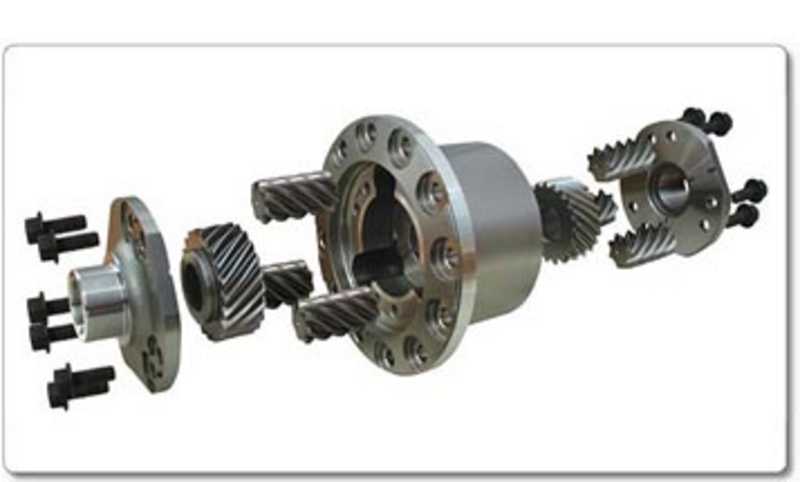
I was explaining helicals yesterday on another site and came up with what I think is my most concise and clear explanation to date, so I cleaned it up a bit and figured I'd repost it elsewhere. Helical diffs work like this: two large side gears in the carrier are connected to the axles, and a bunch of worm gears drive off of each side gear and ride on each other in the center. The worm gears connect the two side gears together, so that when one side gear turns at a different speed than the other, all of the worm gears must also turn. When there is no load (no torque) and the unit is not preloaded (some are preloaded from the factory, some aren't), you can jack up the rear end and spin one side with one finger and the other side spins very easily in the opposite direction. There is probably even less resistance than a normal open diff and spider gears. When you put power to it though, the torque drives the side gears outwards into the case, and all the worm gears get driven inwards to the bottom of their machined pockets in the carrier. The force of these gears jammed up in all of their respective slots is what creates the resistance to differentiation. All of the gears also try to walk off of the gear they're riding on, so there is axial and radial friction between every gear and the case. If you try to spin one wheel at a different speed, it must turn all of the gears in the differential while they're loaded. The amount of force produced here can be quantified by how much torque it can hold. This is what is called the Torque Bias Ratio. Really aggressive TBR's are 5:1, most common are ~3:1. This means that a 5:1 TBR can keep putting power to the wheel with less traction until it has 1/5 or 1/3 the traction of the other wheel and the torque applied does not exceed the traction of the inside tire. If you have less traction available or apply too much power so that you get wheel spin, then the gears inside lose some of their friction against the case. As the speed differential between the wheel speed and the car speed increases on the wheel that is unloaded, internal friction in the limited slip decreases and that tire spins more and more freely. If one wheel comes off the ground and there is no preload, all of the torque goes straight to the lifted tire. As soon as traction is restored, the diff resumes the task of limiting slip. This definition that I've given is not typical, and I know it. Usually you see something like "the differential takes the torque at the wheel with less traction and transfers it to the wheel with traction" or "sends traction from the wheel that slips to the wheel that grips". You might see some math applied: "If the inside tire can put down 100 lb/ft of torque, the LSD will send 300 lb/ft to the outside tire." This is really not what is happening at all. It's more accurate to say that the helical LSD can lock the axles together to a certain degree by applying friction equally to both axles to prevent it, and once you go beyond the limits of the friction created by the diff or the traction available at the lesser tire and try to put torque down, you get wheel spin. There is no gear reduction mechanism in the diff, no mechanism to take power from one side and add it to the other. The limited slip acts uniformly on both sides. By way of contrast, traction control systems actually change the speed of one tire vs the other by applying the inside brake really do SEND the power from one side to the other by limiting drive to the spinning tire and applying more torque and power to the side with drive. Helical limited slips do not do this (no limited slip that I know of does). We may truthfully say that the inside tire is putting 100 lbs of torque to the ground and the outside is putting 300 in a helical example, but the gears inside the diff are still applying the same amount of frictional force to both axles to resist differentiation. Limited slips allow wheel speeds to differentiate for corners and still maintain the ability to resist spinning one tire out of control, but they are not "sending power from the wheel that slips to the wheel that grips". LSDs are like sway bars in that respect. They attach to both axles of the car, so whatever effect they have is shared on both sides. The result of their equal effort can be quantified in terms of how much more power can go to the outside tire before the inside starts slipping, but the effect is not obtained by virtue of the diff transferring power to the outside tire, it occurs because the diff resists slipping and the fact that there is more traction at the outside tire. If you have a clutch LSD shimmed really tight, it might have a TBR of 1000:1 or maybe it would even be locked up solid and be infinite like a spool. But that doesn't mean that a diff with an infinite TBR puts infinitely more power to the axle with traction. It means that it drives the axles EXACTLY EQUALLY and if one side has traction it does infinitely more work than the side that has none.
-
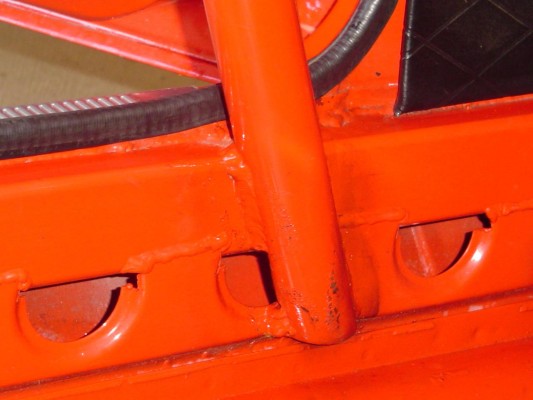
I would fix the last three notches. I didn't even consider putting the door bar brace to the rear stays. That looks like it will work nicely. You can do a gusset or two to the map light bar. I would suggest doing that regardless of whether you thought it would rattle. 1/8" is pretty dang close. Might also be able to cut the front inner corner off the main hoop boxes and put a plate in the resulting rectangular hole rather than cutting the whole thing lengthwise to refit. It looks like you know this already, but clean the tubes before welding. Looks really nice so far!
-
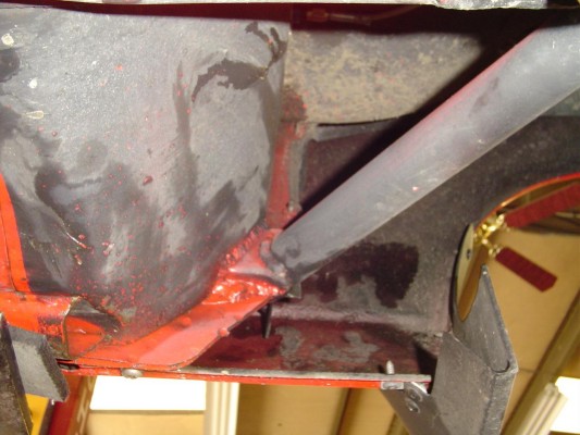
I would do your main part of your cage from the specified thickness required by SCCA, which I think is 1.5 x .095 (double check), and then I'd do all the additional supports in thin walled tube, like 1.5 x .065. It's not going to save a huge amount of weight, but it adds up over the whole project. If you decide to go with 1.625" though, paper towel rolls fit nicely over that size tube, so you can screw around with notches on cardboard and then trace them onto the tube once you have it the way you want it. OK, some of this might not translate too well due to the angles, but hopefully it all makes sense. It's basically a very slight modification of Dan's entire setup with the hoop in the passenger compartment, an X to the front strut towers, and the bars from the bottom of the A pillar to the strut towers like my cage has. Also changed are the main hoop supports and bars from the door bar to the hoop; they now meet together in the front of the strut tower. There is a thick metal plate on the top of the strut tower. Weld your mounting plate to that and you should be good to go. Could even wrap up over the top or onto the wall a bit for a 3 dimensional mounting plate. Here are my pictures of the bar from the A pillar to the strut tower. It really just barely fits and I had to locate the bar further away from the strut tower itself than I would have liked. The closer you get to the end of a tube the stiffer it is (you'll verify this if you get a tubing bender), so it's much better to be right next to the end than in the middle of a span, so it's still pretty good. And here are my drawings on your pictures. I also am not a paint master, so hopefully you get the idea. One thing to take note of is the straight shoulder bar. If you are over about 5'8" tall (guessing) then you might have issues with the shoulder bar interfering with the seat going all the way back. I bent the shoulder bar to allow the seat to go all the way back, and that basically means that I cannot really do the bar from the door bar to the strut tower. Those two cannot coexist built off of the same node, note Dan doesn't have one either. Alternatively you could move the shoulder bar up or down or move the door bars up or down. Ideally you would want the diag to meet the hoop supports, but again, if you're tall you can't have that in a Z because it prevents the seat from moving as well, so that frees up the main hoop support location. I put my rear supports just under the bend in the main hoop, and then put a plate on top of the strut tower trapezoid and welded the support to that. If you decide to ditch the door bar to rear strut tower bar, then you can do this too, and the support would then basically serve the same function in a T bone accident. Might be higher than one would like though. The one thing I didn't include from my own cage is the X from the rear strut towers to the bottom of the main hoop. It was a real pain in the ass to weld in, so unless you're hyper-anal like me, I'd suggest skipping it. If you do add that, cut the stupid shelf out first instead of trying to leave it in the car. I'd be curious to see what some of the other guys have to say as well.
-
I got my order. It included everything EXCEPT the short CV axles. I tried to get a hold of the machinist today, no luck. Hopefully Monday. I'm going to have to take some measurements and talk to him before I advertise the new CV kit, but it looks awesome.
-
Post the pictures without the bars drawn in and I'll give you my take on it. I think you're on the right track with a lot of this, but there's a couple things I think won't work. The bar from the door bar to the strut tower for example wouldn't fit in that location unless you put a bend in it. One thing you could do is an X from the dash bar outers to the strut towers. This is what I should have done on my car. I'd do it with a bolt in outer portion in the engine compartment. You need a tubing bender, not a mandrel bender. A cheap tubing bender costs about $400. I got mine through www.speedwaymotors.com. A pipe bender won't cut it.