JMortensen
-
Posts
13742 -
Joined
-
Last visited
-
Days Won
68
Content Type
Profiles
Forums
Blogs
Events
Gallery
Downloads
Store
Everything posted by JMortensen
-
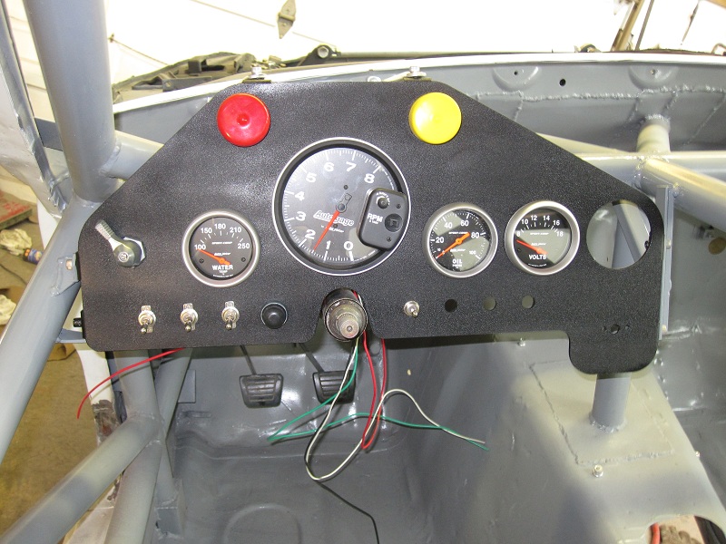
I'd suggest you do an all in one digital dash. That's what Id do if I could have a do-over. Mine (there is a wideband in the far right hole now):

-
Here is the link: https://www.linkedin.com/pulse/how-do-motorsport-ground-effect-diffusers-work-willem-toet This picture is a very nice long time average (allowing the fluid to dry well while running the wind tunnel). This picture shows a little better just how disturbed the flow has become. It probably comes from a slightly lower ride height than the previous picture. This change of flow state is significant and results in aerodynamic “hysteresis”. The two vortices hang on fairly well on the way down but, once burst, you have to come back up to a higher ride height than the burst ride to get the flow back into a nearly “symmetrical” state. The fact that burst and re-creation happen at different heights is what we call the hysteresis. This is why the plot of downforce showed two lines – they are for lowering and for raising the diffuser. Clearly drivers will hate the feel of the car if you allow it to get to these areas of performance change. Continuing to reduce ride height further, leads to reducing energy and attachment of the flow and ultimately to complete separation over the entire width of the inlet of the diffuser. Now the next interesting detail..... Here you can see that low angle diffusers don’t reach the same level of performance as those with higher angles (within the range tested). Once a critical level is reached the higher angle diffusers achieve the same downforce (at different heights). You can’t extend this to silly angles – we have tried! What’s interesting is that the highest angle tested has the largest ride height range at max performance. Those at slightly lower expansion angles fall away more as ride height is increased from the peak (remember 1% is a lot). Now why might that be? Now I’m not going to give away everything I know but one mechanism is this. If a body (or a large part of one) has substantial ground clearance then the chances are that there is air below that body which is relatively undisturbed. If true, then the higher the body, the more air is sitting there not being “used”. Conventional flow expansion in two dimensions is not going to take advantage of that energy (not “all” of it anyway). I often talk about how much energy remains in the air. Now the truth is that the car is moving and the air is (relatively) still so what I’m really talking about is relative energy given the velocity of the car. It’s just easier to think of the air moving for an old man who’s done years of work in a wind tunnel J. The vortices rolling up under the diffuser take high energy air from the outside of the body and introduce it into the diffuser but they also take high energy air from below the level of the body and mix it into the body of airflow that is expanding under the diffuser. That’s one mechanism that allows diffusers to remain attached even at high angles of attack. In Formula 1 diffusers are expanded both in side view and in plan view. This is in part because the height limit imposed by regulation is well below the aerodynamic optimum. There is still a positive impact on pressures and hence forces on the flat part of the floor. The trend towards running ever higher rear ride heights in Formula 1 will be in part because the entire floor can become a diffuser, in part because the teams have learned how to use vorticity to take advantage of all that air that otherwise passes under the car almost “unused”. If your diffuser or floor is wide, then there may be energy in the air inboard of the outer vortices which is not used. Image shows a section through a hillclimb car which I can show because it is my image. Even though this is not a conventional diffuser, you can see the vortices on the outboard parts of the floor section. The colours represent total pressure (energy) and the lines (line integrated convolution for the CFD techies) show airflow directions in the plane of the shot which is a cross section of the car near rear axle centreline. There is a lot of high energy air here not being “worked” yet and in a way the height won’t allow a single vortex to engage all of that air – a vortex has to be relatively circular in cross section. If you add an additional fence or strake (a vortex generator of any design really) in each side of the floor it is possible to roll up two more vortices which take advantage of that airflow energy to create downforce. This clearly isn’t an optimised design yet but it serves the purpose of showing what might be done. If I see high energy air exiting the floor of the car (at the most critical low ride heights), I look to find a way of using it. So, hopefully, this explains what fences in the middle of a diffuser do (some part of their function in any case). For additional reading there is a decent section on diffusers in Joe Katz’ book “Race Car Aerodynamics”. I think that has to do for one (monster) post – I’ll cover some other important aspects about diffusers in other posts (oh yes, there is much more!). Still here? WOW - I'm impressed you could stay awake! I love this stuff but it really is for aero nuts like me. For my other posts see :- https://www.linkedin.com/today/author/187006218
-
He is not on the forums that much. I will tell you that when I shut down my diff parts biz I talked to him at length several times about the CV binding issues. I sent him the technical drawings for my shorter Z31 shafts that I was making and he continued to make them. He is well aware of the CV binding issue. His 930 kit is something that I tried to get done to no avail, and we talked at length about that as well, and he incorporated the design changes that we talked about, which were specifically to allow for more plunge, into his design. If he says it fits S30s, I wouldn't doubt it.
-
Joe is a racer who preps mostly British cars: http://www.chequeredflagracing.net/ I would say he's a car guy. 930 CVs and shafts are not something new, so I don't know what part of that needs "proving". If they're using 300M joints, shafts, and stub axles, that's going to be as strong as they get too. As for the shafts bottoming, the 930 CVs have a lot of plunge depth. The stock Z31 shafts have about an inch and a quarter of movement as I recall. The 930 style probably has that much on each joint. Since this kit is only available for the R200, the difference in length between 240 and 280 chassis isn't a problem at all. Just put the shaft length in the middle and there will be more than enough plunge to compensate either way.
-
The problem with DSS's kit is it bolts to the stock companion flange and doesn't replace the stub axle. I know they advertise when they do use 300M, so I guess they're not in this application. DSS makes good parts, so I'm sure their CV axles are just fine, but they're evidently not using the strongest material, and they're missing the stub axle, so it's incomplete. Joe, congrats on getting that kit together. That's a kick ass kit you have there.
-

Stiffer springs vs bumpstops
JMortensen replied to RebekahsZ's topic in Brakes, Wheels, Suspension and Chassis
I think zero lift would be great, but that's not likely to be what you'll have. -
Stiffer springs vs bumpstops
JMortensen replied to RebekahsZ's topic in Brakes, Wheels, Suspension and Chassis
I dunno. I think I'd want level or rake. Screw the drag, I want the front on the ground. Seen this, Keith? https://youtu.be/D59x_2PyUcc?t=8m7s -
Agree the rod is too long or pedal is misadjusted and the master can't fully retract. Had the same problem after misadjusting my clutch. More I drove, the more it slipped. Crack the bleeder and release the pressure and it was fine again.
-
Manual transmission options
JMortensen replied to skibumspence's topic in Gen III & IV Chevy V8Z Tech Board
Nice. You dry sumping it also to take advantage of that smaller diameter bell housing and get that drivetrain lower in the chassis? -
Manual transmission options
JMortensen replied to skibumspence's topic in Gen III & IV Chevy V8Z Tech Board
Agree with Keith for the most part. T56 is stupid heavy and 6th is useless. The stock World Class T5 is supposed to be weak also. Despite the weight, I'm running the T56. Adapters are available for Super T-10 4 speeds to LS engines, but you'll either need a 4 speed with overdrive (don't think they're easy to find) or really tall gears (definitely not easy to find for the Nissan diffs anyhow). -
Would need a rear steer rack. I think that the some 280ZX came with one, but not positive.
-
Moving the steering rack forward
JMortensen replied to grannyknot's topic in Brakes, Wheels, Suspension and Chassis
Nope, they actually do have a little ackerman out of the box. -
TC rod mount ideal location?
JMortensen replied to heavy85's topic in Brakes, Wheels, Suspension and Chassis
I don't think you'll get anywhere near anti-dive. I have a big slotted bracket and I couldn't get the TC rod level. at ride height. Just guessing, but I'm doubting you'll be able to feel any difference in those adjustments. -
The front LCA mount is pretty stout, nut the rear isn't. Could improve this design by tying into the rear uprights, or replacing them entirely with something stronger.
-
Are the bc's are built as a shock or a strut? I know I've seen damaged shocks that were used as struts. That would be a big problem. The dyno sheets looked really good though so it would be tempting to get them and rebuild if they could handle the loads.
-
I think the right answer is either a cradle that attaches front and rear mounts together with a top mounted bushing, or a top mounted pinion snubber or mount that isn't attached in front or in back of the snubber/mount itself, so it isn't wanting to twist when you put force on it.
-
S30 rear control arm question
JMortensen replied to Kamaka Z's topic in Brakes, Wheels, Suspension and Chassis
The 280 arms are built stronger all over. Thicker tubing wall on the inner pivot, I believe the rest of the metal in the arm is thicker as well, reinforced at the outer bushing apparently too. For that reason I'd stick with 280 arms on a heavier 280 car. 280 arms for anything, 240 arms for 240s is the way I'd think about it. That said, control arm failure is not something you come across a lot. -
Modifyed Miata power steering rack for 240Z
JMortensen replied to BoonZ's topic in Brakes, Wheels, Suspension and Chassis
You're correct on the Woodward gear changes. Tony over there told me they weren't doing that anymore, I guess it was too much hassle to set up correctly. For a new one, you buy a rack and get the gear ratio you want up front. -
Modifyed Miata power steering rack for 240Z
JMortensen replied to BoonZ's topic in Brakes, Wheels, Suspension and Chassis
Agree that rack speed is a huge advantage, although you can get most of the way there by putting a 1.5 quickener in line. My Woodward is about 1.75x faster than stock. I had to decide between the 2.66 and 3.14 per turn racks, ended up going with the 2.66. Now that I've driven it at an autox, I know can get my wide car through slaloms without hand over hand, but I'd probably go 3.14 if I had to do it again. On bumpsteer, I think that you can tune it out to a point where there are better things to concern yourself with. Mine is 23.75 CTC for what that is worth, and I after minimizing bumpsteer through shimming I didn't notice any issues with it on track. -
Modifyed Miata power steering rack for 240Z
JMortensen replied to BoonZ's topic in Brakes, Wheels, Suspension and Chassis
Looks like he was very specific on trying to get the tie rod lengths and the LCA lengths the same, presumably to minimize bumpsteer. -
Finned Aluminum Nissan R200 extra capacity diff cover
JMortensen replied to Rob L's topic in Price Check
No kidding. You could probably get and external cooler, pump, and plumbing for that price. -
LOL. Forgot about that one! What a crappy idea.
-
Try the way back machine: https://archive.org/web/
-
What you need, IMO, is a cradle that locates the front and rear diff mounts and bolts to the chassis (might have to make a new mounting point, sounds like yours is pretty F'd. If you look at this guy's pics, you might find some inspiration. https://www.facebook.com/TSSFAB.US/photos_stream
-
TC rod mount ideal location?
JMortensen replied to heavy85's topic in Brakes, Wheels, Suspension and Chassis
Then you have sway, steering, and TC rod in the same space. If you were changing up the steering a rear steer setup would allow for lots more ackerman. Some of the aftermarket units that use a inner tie rod end rather than a rod end don't change the length as much, so that would minimize any potential negative effect.