JMortensen
-
Posts
13742 -
Joined
-
Last visited
-
Days Won
68
Content Type
Profiles
Forums
Blogs
Events
Gallery
Downloads
Store
Everything posted by JMortensen
-
I've got instructions done and I'm going to email them out to everyone and they describe how to measure the CV free play. I haven't tried to figure out the length of the shaft to the flange without considering the CV, so I can't say what the correct dimensions would be when doing it that way. I can say that the right side shaft on the US cars has a longer spline on it and if you put it on the left side and installed it until it clicked into the diff, the inner CV would be about 3/8" farther out than it would be installing the correct length left side. That in itself could throw everything else off. We're anticipating 1/4" to 3/8" of clearance, so if you start with 3/8" less space, you might be inclined to think that it won't fit at all.
-
In laws are looking for a cheap commuter, and they've found a Yaris. I know nothing about appliance commuter cars, but wondering if anyone had any feedback or suggestions on something else that would be better. They're looking at used and spending about $10K.
-

Ground Control Camber plate install methods
JMortensen replied to svMike's topic in Brakes, Wheels, Suspension and Chassis
Give them a call. Jay has been VERY helpful to me over the years when I had questions/issues. -
Ground Control Camber plate install methods
JMortensen replied to svMike's topic in Brakes, Wheels, Suspension and Chassis
I think you must mean AZC or TTT. GC plates are aluminum. Agree that you don't need another plate if you're using one of those. I think the metal in them is 3/16" thick anyway. -
Ground Control Camber plate install methods
JMortensen replied to svMike's topic in Brakes, Wheels, Suspension and Chassis
It probably would be stronger if the plate underneath was stronger than the original camber plate. -
When you jack the car up the suspension droops and the struts extend all the way. Full bump is when it is all the way compressed. We're being cautious with our measurements and we're doing a recall, so I would suggest that you don't drive it.
-
Ground Control Camber plate install methods
JMortensen replied to svMike's topic in Brakes, Wheels, Suspension and Chassis
If you bolt the plate on top, then you basically have the nuts holding the suspension on as you might hit several g's of loading. Not good, but I think a lot of people actually drive their cars like this. If you install underneath, then the plate spreads the load all the way around the strut tower. You might put them on top if you made a doubler plate for the bottom to add strength like Mongo did, but either way you'll need to slot the tower because you need the slot to actually move the camber. Another option is the biscuit style plates. They don't require any slotting or cutting, but you only have fixed positions available, so you won't be able to change from -2 to -2.1 camber for example. -
Middle of the travel is about 5/8" gap, so we're really not that far off from where we need to be, but we need to remember that droop is the start point. So if you start at 7/8, you're already 1/4" past the center and moving further inboard as the suspension compresses. On my car I got 3/8" of movement, so you're 5/8 past the center at full bump if your car measures out the same. Assuming that you're using stock control arms, you really shouldn't get near the end of the travel, as I said before, but there are variables that we can't take into account like camber bushings, longer control arms, camber plates, etc. By swapping the shafts, you'll start with about 1/4" gap and at full bump that should be about 5/8", right in the middle, but you'll have room for camber bushings and longer control arms, etc. and if you're putting down huge amounts of power you won't be close to the end of the cup, where the groove for the CV clamp is machined in.
-
Lead time on new shafts is 3 weeks.
-
Yes, I would like to hear from as many as possible as quickly as possible. I'm checking on the lead time on new shafts. Our conservative "safe zone" on these shafts is going to be from 1/8" at full droop out to 1.125". At 1.125" the balls are riding about 5/8" down below the outer snap ring with the shaft straight. Even at 1.25" the balls are down in the cup 1/2". They're really not that close to the end. The problem is that there is angularity at the CV which moves 1/2 of the bearings closer to the end of the CV and 1/2 farther away, and this angularity will vary from car to car. The angularity is less of an issue at full bump because the CV joint gets straighter as it approaches full bump (this is why the shafts need to be shortest at droop) so we are really erring on the side of being cautious. Part of the idea behind these shafts was that people would be able to lengthen the control arms as well. Our measurements were wrong and biased the ball bearings further out in the CV joint than we had intended, and we also found that the CV joint has less plunge available than previously figured. These shafts should not have issues on a "normal" Z car, the problem is that people who will buy this product don't have "normal" cars. I know that there may be some loss of confidence in my ability to figure this out, so I encourage everyone to double check me yourselves. Instead of taking the measurement of the parts when disassembled and then figuring out the stroke in the CV with math, this time I've assembled the CV and used physical spacers underneath the cage of the CV to figure out where the balls will be with the shaft on a bench.
-
OK guys, we have another problem. I was writing up installation instructions and I came across a picture that shows exactly what matt_w just asked, and it is pretty clear that the balls do NOT ride in the center of the race. After seeing this I went out to the garage and took a look, and figured out that all of my measurements are off because of this discrepancy. The balls are about 1/8" farther to the outside of the CV cage than I had figured, and the available travel is about 1 3/8", not 1 11/16. We don't think that the CV's will top out because of the minimal amount of CV travel, but it's close enough that we don't want to let it go. Therefore we're going to do a recall. We are going to recall the driver's side shaft and customers will use the M2 passenger side shaft on the driver's side. A new passenger side will be made 1/2" longer and will be replaced free of charge. Of course, we have to order the new shafts so there will be a delay. For those who need to use their car right away, the stock driver's side shaft is 1/2" longer than the passenger M2 shaft, so you can swap the passenger side M2 to the driver's side of the car and run the stock driver's shaft on the passenger's side and that should put the balls right in the middle, although the shafts won't be chromoly. Any customer who would prefer to use the stock shaft with our long shaft can have a 50% refund. I apologize for the inconvenience, and I will again try to contact everyone who purchased these shafts (again) to let them know of the problem and our solution to it.
-
The cage won't change the position of the balls, because the balls still ride in the middle of the race regardless of which orientation the cage is in. Based on the info you've given I think you're good to go, you're pretty well centered in the joint.
-
The CV has 1 11/16" of total movement. The housing is 2 13/16" tall, and the inner race is 1 1/8" tall, so the total range of motion of the balls as measured from their center is from 5/8" away from the bottom of the cup to 2 3/16" from the top of the cup. 1.25" of free space means that you will have the center of the balls about 15/16" from the snap ring groove. The wear pattern on my 300ZXT outer is centered at 1 1/16" from the groove and you're at 15/16" which is almost identical. Obviously we can't vouch for the used CV joints or anything else on your car as they weren't supplied by us.
-
The Chequered Flag stuff is made by the same guys who make MM's parts. I have the 39 spline stubs and flanges from Ross on my car and I can tell you that the shafts were measured off of those pieces. It shouldn't matter if you have M2, Chequered Flag, or MM billet or welded adapters. They'll all work fine and be close to the middle of the travel (the MM welded parts will be offset about 3/8" to the exterior).
-
Doesn't really matter, but droop is easiest unless you're going to back the car up on ramps.
-
Cool. I'll take you off the list of people to call. Still have about 20 calls to make.
-
The question remains, was Josey's car tweaked or bent, or is it manufactured differently than the earlier 280Z like Carjway has? I really don't expect that the car is built differently, because so many people use the mustache bars and the link for the rear control arm bushings out of the 280s on 240s that you would figure that this would have come up sooner if those parts were different. The weirdest part about Josey's situation is that the passenger's side shaft fits correctly, but the driver's side is too short. This doesn't make a whole lot of sense to me. Still, the situation is a bit worrisome and I'd hate to see someone else having this problem. We're going to contact our customers who have purchased these shafts and ask that they disconnect the CV from the companion flange and measure the gap, and add that as a step in the instructions. If the gap is greater than 1 inch, we can swap out the short shaft for the long shaft at no cost, or they can run the stock driver's side shaft on the passenger's side and the M2 passenger on the driver's side.
-
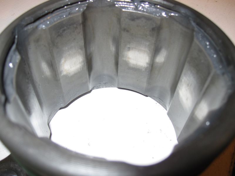
I've never personally bottomed the shafts so I haven't seen the dust caps after that, but I've read about them being getting chewed up. I think the shaft hits the stub axle pretty quickly, so it's more of a dent in the middle of the cap. I figured out that the length of the CV was a problem on my own car and made my control arms longer (I was building new control arms anyway to go to heims joints). A little bit about what we know: Josey has stock control arms and camber plates, and poly bushings, so I don't think that any of that is a likely culprit. I'm sure that the CV was pushed up the shaft when the two pieces were separated and binding on each other. It seems like the CV was able to pull out just far enough for the joint to spin inside the boot, but not far enough to come all the way out, this really sounds like Jay Hitchcock's experience. I tried to find his thread from probably 7 or 8 years ago and couldn't locate it unfortunately. Jay's was actually short enough to separate completely and so the tripod end of the CV was flopping around in the suspension. Josey says that he measured from the diff to the companion flange and he thought that it was the same distance on both sides, which is not what we've found on 240s that have been measured, and not what could be seen on Carjway's 280Z either. Carjway's car matched my expectations exactly. So maybe there is a later version of the 280 chassis which has the diff moved 3/4" to the right... ??? I believe all the mustache bars are the same, so that would mean that the studs that the bar hangs from would have to be offset. Other than that, I'm not really seeing how this could happen. I've asked him to reinstall the CV, pull the CV all the way back from the companion flange and measure the gap. If the gap is greater than about 7/8", then we know something is funky on his car. If it is 7/8" like the others, then we have to try and understand what could possibly have moved so far, because there should have been another 13/16" of engagement (1 11/16" total CV movement available), so either the strut had to move outward that far or the diff had to move to the passenger side that far for the CV to pop out. At this point I don't see how either of those things could possibly happen. He also says his car is not obviously damaged, so it doesn't appear that this car was hit hard in the rear and then fixed badly. If anyone would like to double check this issue, disconnect the CV from the adapter via the 4 bolts and measure the space with the CV bottomed and make sure you're in the middle of the range. I've got a 300ZXT outer CV cage in my office here, and you can clearly see that the shiny wear spot from it's original tour of duty on a Z31 is right in the middle of the cage (pic below), so I don't think that there is any question that the joint is designed to be run in the middle where these shafts are intended to put it.

-
If the inner part of the CV pulled out of the cup, that means that the shaft is too short on that side. I don't see any other way that could happen. Jay Hitchcock had similar problems with a 280ZXT CV shaft that he had made to the wrong specifications. He had another set made longer (but still shorter than stock) and solved his problem. I'd like to see what happened to your shaft, maybe you could send it to me. There is a little bit of slack designed into the splines, and so the inner race can move a little bit (.050 or so is totally normal), but it shouldn't be jammed 1/8" up the splines. I have a feeling that may have happened after the joint came out of the cup. The question is: Why is the shaft too short in your car? Do you have aftermarket control arms which are longer than stock? I don't think camber bushings would allow enough travel to be a problem, but are you running them, or anything else that might cause the distance from the stub axle to the diff to change? Since the LH is the side with the problem, it's impossible that you could have put the short shaft on the wrong side. What was the distance that you had between CV and the adapter when you bolted it on? Should be about 3/4" and that should be right in the middle of the CV's travel. Since there is only about 3/8" of movement of the CV in the cup as the suspension moves, it seems very unlikely that the CV could disconnect from the cup if everything else was correct.
-
SU's and vapor lock
JMortensen replied to PurePontiacKid's topic in Trouble Shooting / General Engine
Rubber hose instead of the fuel rail. Just making sure you got that part. -
SU's and vapor lock
JMortensen replied to PurePontiacKid's topic in Trouble Shooting / General Engine
If you're using a mech fuel pump, get rid of it. Get rid of the rail and run a rubber hose instead. I ran mine from the filter in the front corner of the engine bay across the rad support and then back to the carbs. I don't know where the lines run in the ZX, but I'm sure it's something similar. I had vapor lock issues with the SU's before those two mods, never had trouble after. -
I don't know about "lots" of tuning, sounds like you're getting it dialed in pretty well. At some point that energy should be directed somewhere more useful. They are triple carbs after all, and you're getting very good results. High 20's mpg cruise is great. Definitely want leaner at cruise, 13:1 is WOT afr as far as I'm concerned, I think you're in the right ballpark. As Tony said, you're not needing a lot of power at cruise, so no point in dumping a bunch of extra fuel in there. As to why the pilots need to be 1 or 1.5 turns out, nobody really told me the reasoning why, but I think it has to do with the adjuster screw getting far enough away from the pilot that it's essentially wide open, so that more adjusting isn't really doing anything. Gross exaggeration might be comparing it to adjusting nozzles on SU's in an attempt to change WOT afr's. I'd try the larger pilots with the adjustment in the right range. Fuel percolation is a problem that I never ran into, but it is something you hear about quite a bit, so if you don't have a heat shield, it's not going to hurt to put one on. I did have some vapor lock issues with SU's and I did two things to fix: I got rid of the mechanical pump and used an electric, and I got rid of the metal fuel rail and just used a rubber hose. After making those changes I never had boiling issues again, and I kept those changes with the switch to Mikunis. Still think timing could be a factor if it is too far advanced at idle.
-
Didn't see your results, congratulations! Your videos aren't showing for some reason, would like to see them. This you? I was thinking it might be when I first saw the picture, but you're not real close to the dragon. http://www.facebook....&type=3 background here: http://www.facebook....&type=3
-
If the straw is the wrong size, how about some heat shrink tubing? Haven't tried it myself, but should work I would think...
-
Doesn't the stock L28ET pretty much stop accelerating after about 5500 rpm? No experience, but I had I thought that I'd read the cam timing was such that it wasn't worth it to try to hit 6500. Nevermind, I see he's saying he's shifting at 6500 or 7000. If it has a stock cam, might check the tach accuracy.