ETI2K
-
Posts
39 -
Joined
-
Last visited
Content Type
Profiles
Forums
Blogs
Events
Gallery
Downloads
Store
Everything posted by ETI2K
-
Need image of '76 280Z fusebox cover
ETI2K replied to ETI2K's topic in S30 Series - 240z, 260z, 280z
It sure looks right. Thank you very much for sending it along. Progress is being made in sometimes very small steps. -
I have a similar problem, but maybe bigger. I have two door shells that came from my car - with no skins at all. The originals were removed to deal with the same problem Boost has. Unfortunately, the skins were damaged beyond any hope of use in a tragic sandblasting operation. 😫. I bought two replacement doors 20+ years ago but they go to a late 76 280, mine is early. So I've been considering removing the good skins and installing them on the correct shells. I figured I'd drill the spot welds, warm the flanges and pry them open - as grannyknot suggests - as little as possible. Reinstall would be plug welding through the old spot weld holes. Anyone ever attempt such a thing?
-
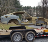
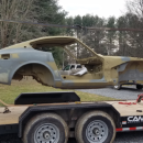
That is a good looking start! It might serve you well to do a lot of careful inspection of the common rust areas before you begin assembly operations, in case someone didn't do proper repair work. I am starting a 76 in the same condition (disassembled, not painted), and making changes to wire harness currently. Actual assembly will be sometime next year, after I get a shop built. I'll be looking forward to seeing your progress. Congratulations!
-
Thanks for the info. I appreciate it.
-
I'm in the process of making wire harness changes that include upgrades and additions that will increase the total current requirement from the alternator/battery. Ultimately, besides wire gauge changes, the alternator will need to be upgraded. For this calculation, I started with the belief that winter and summer might be very different. Turns out, maybe not so much. Loads are computed at minimum charging voltage: 13.5 (arguably). Lighting current is based on using incandescent bulbs which also will see "persistent" and "transient" use. The persistent load comes out to about 17A, while transients total around 16A. I took a WAG and chose 25A for both. Some other transient loads, such as power windows, are not included. Audio equipment is not included. The highest load case in this example is 134A. If you believe in safety factor, and I most certainly do, it looks like I'll need at least a 150A alternator. Has anyone successfully used an alternator rated in the 150 - 200A range?

-
That's a very elegant solution. I especially like the way you used the circumferential groove to captivate a threaded fitting and standoff for securing the sensor - that's sort of a question, really, to be sure I am seeing it correctly. Been looking for a way to implement a cam sensor for a while now. I think as soon as I can run my lathe again, I'll do the same thing. What vehicle is the sensor for? EDIT: Found one from a '95 Audi 90 that looks similar. Never underestimate what one can accomplish when there's nothing to do but sit in front of a computer for countless hours a day. 😁 Thanks for sharing your design, tioga.
-
Would anyone be able to snap a pic of the plastic fusebox cover showing enough detail to read it? I am making corrections and updates to a color wiring diagram I found (here, I think), which I will then make available as .png file to anyone wanting it. Once the wiring diagram is complete, I'll use AutoCAD to create a modified diagram for the wiring changes I am making to implement Megasquirt, which I will also make available.
-
What is the ring groove depth on a stock 280 piston?
ETI2K replied to ETI2K's topic in Nissan L6 Forum
Any chance someone has an old 2.8 piston lying around and could measure the groove depth? Any help is appreciated. -
It seems the consensus is to use cavity wax as the primary (last step) moisture-proof sealer, which makes very good sense. Of course, the issue is what to do before that. Since my car is on a rotisserie, I can orient it as needed to position certain openings 'down'. Then flood the cavities with ZRC until it runs through any openings between welds, sealing them against moisture and offering sacrificial protection . After lots of cure time, finish with cavity wax. The problem with ZRC, like any zinc product I guess, is most paints don't do well as a top coat, so you have to remove any that makes its way to a finish surface. Small price to pay for the protection afforded inside the dark recesses of these cars.
-
Looking to install Total Seal rings and they need that spec to determine the ring pack. The factory service manual does not include that one small detail.
-
So much fun to be had. Looking like my dash is arriving tomorrow!
-
 How did everything look inside? I am planning to do the same work on mine. New bearings and synchros for certain.
 -
Check this YouTube video. Looks like a very well thought out test. I'd love to have seen more products tested such as ZRC, Rust Bullet, Kryptonite, etc. Many years ago (around 1996 maybe) I tested the lot of rust preventers on the market, including latex-based rust converter, Eastwood Heavy Duty Anti-Rust, ZRC (Zinc-Rich Compound) and Corroless. The test was fairly simple. I started with clean sheet metal (1012-1018) and coated each piece as directed, except I did not coat the edges as I wanted to give the corrosion a "path" to the faces. After curing, I scratched across each face with a sharp tool to cut through the coating, then sank the pieces into a sink with salt water in it, and kept the salt water fresh by changing it out every couple of days. After a few weeks, the ZRC-coated steel was the only one that had not categorically failed or rusted. Most of the coatings lifted from the metal (that started as bubbling - not intrusion of rust from the edges) and began to rust where the surface became exposed to the salt water. https://www.youtube.com/watch?v=lyWHF4NoNVk
-
Hmm, very good to know that about cracking. Thanks My reasoning for stainless was that the upside down hat design provides no way for moisture inside the profile to drain or evaporate well, so eventually, water will collect and settle at the bottom of the frame rails. The OEM spot welds assure there will be no 'coating' to stop corrosion at the weld sites either. So the obvious question becomes, how do you prevent your repair from rusting out again? I have no experience with weld-through primers in that regard and wonder about how they can protect if they've been burned and never get a top coat. Uncoated continuous butt welds can only experience surface rusting since there are no small cavities for water to collect as there would be using stitch welds. Also it would seem butt welds would endure better than a "pinch" weld (spot or plug). So that's for the continuous floor pan to side of frame rail welding rationale. As for corrosion, I agree dissimilar metals can have great potential. My strategy there was, after welding, to spray (with an undercoating spray system - fan, reverse slash, shotgun type nozzles, etc.) ZRC into every cavity until it started to drain from the weep holes. I had holes placed in the bottom of the frame rails for that purpose, besides letting water out. The rationale for stainless comes from my belief that you can't really see inside a cavity where several pieces of sheet metal come together to be certain you've coated the metal thoroughly, and I was intent on fixing this car only once. So I reasoned the dissimilar metals potential was less of an issue than the potentially uncoated carbon. Further, I had planned to lower the car and believed eventually those frame rails will become skid pads. Of course, that thinking is know more than 20 years old and I know new coating materials, processes, and tools (can you say borescope?) are available. I'd love more feedback on the corrosion issue. Maybe there's a (many?) threads out there already. I just haven't looked yet.
-
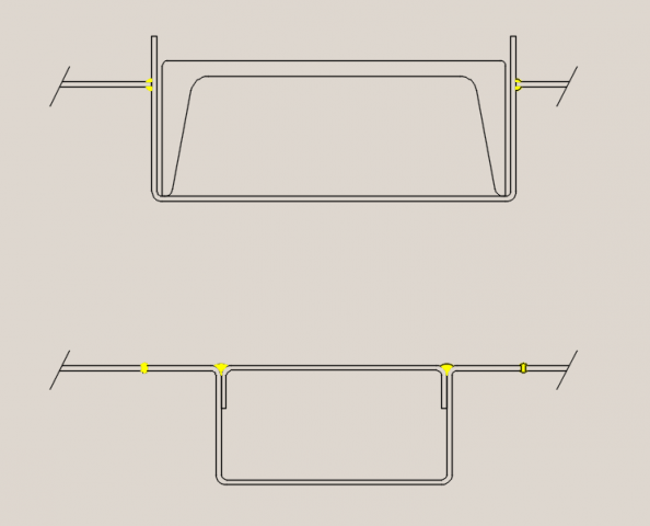
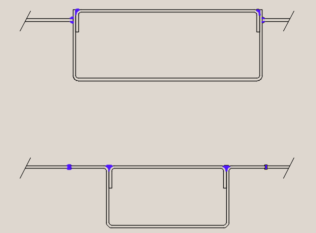
When I replaced my frame rails I cut out the section of floor that included the frame rail flanges, making the opening 4.25" wide. I then had stainless frame rails made with tops (see drawing - as-is at top, new design at bottom) and welded them in, but I'm not really liking them now, so I will likely redo them. The rails and tops are each u-shaped with one fitting inside the other. I welded the edges of the floor pan to the sides of the frame rails because the OEM pans are not flat and I couldn't figure an easy way to deal the changes in height - in other words, I could not figure out to butt weld the pan to rail flanges. This resulted in the side of the frame rails protruding above the floor by about 1/2". After welding (continuous by joining all stitches) I ground off the protrusions, but they still are about .25" above the floor. The reason I am redoing them is I ended them the way the originals ended, so no tie-in to the rear frame; and the tie-in at the front is completely cocked up because the new rails are wider than the members to which they need to be attached. On the next go, I'll have them made to the factory width, extend them to the rear frame area, and include flanges of the sides that reach out to the floor pan edges. This means I will have to flatten the area of the floor where they meet so I can get good butt welds. My primary objective in all of this is to avoid faces of two pieces of carbon steel being pinched together in any way by plug or spot weld in order to avoid rusting at the weld (even with weld-through primers - not 100% on-board with how they hold up over time after having burned off at the weld site). Can you post pics of your rear-mounted sway bar, and also, how are you tying in the new rails at the front?
-
Would you mind sharing details of your wheels (make, diameter, width, offset) and tires?
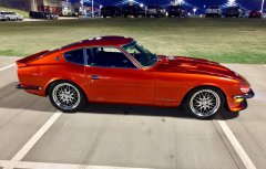
It's a very nice look. Love the color as well. Planning to do mine the same way (HOK, candy, etc.) just in red.
-
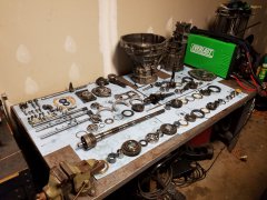
Now that's the way to break down and organize the disassembly of a complicated system! Very nice.
-
The 76 280 I have is my second. I bought it in 1994 as a perfectly sound and decent running car. In the first couple of years I made some changes to start the inevitable restomod that I knew would one day come. By 1996 I had worked the engine with a slight compression increase via shaving the head, stage 2 Crane cam, headers and exhaust, some minor suspension work, new seat covers and carpets, dash cap, and bodywork and paint. The car was great and I loved every minute of driving it hard and quick. Unfortunately, one of the revisions I had made under the hood resulted in the lower radiator hose coming into contact with the alternator cooling fan but only while the motor was under heavy load. It took a while for the hole to develop and eventually wiped out the motor when it overheated. But in loss comes the opportunity for renewal. So the motor work began anew. Cut the head again, decked the block, same cam, bored over, balanced and blueprinted, lightened flywheel, and changed to a 5-speed. However, while doing all this work the dark clouds of a brewing storm were becoming too obvious to ignore. I had frame rail rot plus front strut towers, rockers, doglegs, rear wheel arches, and some very minor floor pan involvement. The time had come to make these vital repairs. With the car on its wheels I started cutting and welding. One day I was working on the rocker on the RH side and very thoughtfully tied back the wire harness running just inside the car to keep away from the weld heat. So down I go under the car again and after about 10 minutes or so I smell an unusual odor. Hmm, I say, left's have a look inside. Well while I was patting myself on the back for the attaboy I so richly deserved to think to get the harness out of the way, I had failed to secure the end of the rope I used and left it hanging - you guessed it - right over the spot I was welding. It's amazing how cotton rope will burn - took out the wiring harness and door panel. Ahh, lessons learned, and, oh boy, more work. That led to my completely disassembling the car and putting it on a rotisserie. Wow, does that make welding easier. That was 1997. Its now been 23 years since that day. Over the years, the only work I was able to accomplish was to remove ALL rusted metal and weld in new or handmade parts, and have the entire car blasted clean and acid-etch primed. I think the last time I touched it was 2003. Jump forward to 2020. I just retired (yahoo!). All I have to do now (since moving) is build a new shop. Once done, there is no thing (sic) that will stand in the way of completing this car. Plans include: Re-examine crank and mains fitment (ala PMCRaceEngines, et al) TotalSeal rings Megasquirt - Full sequential fuel and spark Z-Story stainless headers and exhaust line Adjustable LCAs BC Racing coilovers 2-Groove balancer (BHJ seems to be the only one) 240 bumpers Xenon front dam Rear discs/ Front 4-piston Vintage Dashes Trans bearings and synchros Diff bearings Halfshaft rework Nostalgic AC compressor and hoses New (handmade) Cu/Ni brake, fuel, clutch hydraulic lines Refresh wiring harness - new connectors, solder terminations, eliminate unused (Megasquirt to replace) Port and polish Rebalance and blueprint New injectors Sound/thermal insulation Convert to crank trigger Considering Oil and coolant level sensing Ceramic coating headers Ceramic coating exhaust line Still Struggling Wheels? Tires? Thanks for being patient while I got all that out. I'd appreciate any thoughts/suggestions/etc. Rich
-
Power drain from Timing Chain / Valuable Build Tips herein...
ETI2K replied to galderdi's topic in Nissan L6 Forum
Having read this entire thread, there are several comments relating to the geometry changes the timing chain undergoes when, in effect, 'a head has been cut too much'. Interestingly, with all the discussion of how to measure and fit cranks and bearings (thanks to PMCRaceEngines!), no one challenged what "too much" equals. I built an L28 many years ago with an 0.080" cut to the head along with other mods for a mild build (no intention to race this car). One sad evening while driving on the interstate at night, enjoying those great engine sounds and not paying attention to my coolant gauge... So on the inevitable rebuild, it took another 0.028" cut to clean the head. So total head height reduction = 0.108". To make things even interesting, the block was decked 0.005". I drove the car about 5,000 miles with the refreshed engine and had no problems at all; and then decided to do a complete rotisserie renovation. The car has been on the rotis ever since (22 years😩 - one of the many costs of self-employment). So this year I am resurrecting the restoration, starting with a teardown of the motor and hence, my question: How much is "too much"?