
pparaska
-
Posts
5087 -
Joined
-
Last visited
-
Days Won
3
Content Type
Profiles
Forums
Blogs
Events
Gallery
Downloads
Store
Everything posted by pparaska
-
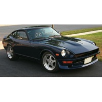
Shaggy - LoL! yeah, except when in my 500hp 240Z, or the "new-to-me" 2000 BMW M5 w/ 440hp
-
Thanks, guys! Just saw this! Old man, for sure!
-
jim, as usual, a great arm chair engineering analysis. It all sounds correct to me. So a thick aluminum cover/girdle MIGHT be stiff enough, but a fabricated steel one might be a solution.
-
I've searched and not seen mention of the problem and no solution. Having roughly 500 ft-lb of torque means that my diff cover bolts come loose quite often. I checked today and some were out 1 turn. The issue is that the flexing of the R200 case under that much torque loosens the cover bolts. Some of the US differentials have aftermarket cover/girdles available to help with this - they use longer bolts that go through the cover/girdle and down to the bearing caps. Has anyone ever designed a cover like this? What would be cool is a finned cover with a girdle integral to it. Any other options? I'm considering safety wiring the bolts but that won't help the flex.
-
Low $ Low Profile Air Cleaners...again
pparaska replied to BillZ260's topic in Gen I & II Chevy V8 Tech Board
Here is the link: http://www.rickscamaros.com/product.asp?pf%5Fid=EP%2D102&dept%5Fid=3152 -
I used: -JTR engine mounts, - Professional Products "Crosswind" copy of the Edelbrock Airgap RPM (not sure if the carb flange height is exactly the same), DID NOT USE THE JTR 1/2" spacers between frame rails and crossmember I used a 1/2" (divided, wood) spacer under the Holley 830 HP carb (to get the air cleaner to clear the extended thermostat housing to get a radiator cap above the thermostat at the highest point to bleed air) My air cleaner is the Moroso 14x3 dropped base. I have VERY LITTLE clearance, less than 1/4", but it does not hit the stock hood.
-
Premier Motorsports Park Planned for St. Mary's County Maryland
pparaska replied to S30TRBO's topic in Non Tech Board
I'm hoping that Mike is correct and my fears are unfounded. I'd love to have a place this close to go for fun! -
Premier Motorsports Park Planned for St. Mary's County Maryland
pparaska replied to S30TRBO's topic in Non Tech Board
I'm not holding my breathe. My guess is that NIMBYism will kill this project if other factors (funding, etc.) don't. Sorry to be so negative. I would love another nice track near me. -
Well, I still own the L24 I pulled out of my Z 10 years ago. And it is sitting under the workbench, holding down the concrete floor.
-
8 years ago, before the engine started - this is with the 327. Doesn't look this nice anymore!
-
I love the simple and straightfoward engineering. And the use of ProE . COOL!!!!!
-
I didn't see where anyone mentioned 200lbs. It seems you're alluding to a 200lb difference between a 302 Ford SB and a SB Chevy engine. I'm saying I SERIOUSLY doubt such a number. Please cite some references.
-
If you have a Chevy V8: http://store.summitracing.com/partdetail.asp?part=MAA%2D29003&autoview=sku or for a Ford V8: http://store.summitracing.com/partdetail.asp?part=MSD%2D8522&autoview=sku ^^^^ the beauty of hotrodding a very common engine is that the uncommon parts for stuff like this are COMMON. But for the true hotrodder, anything that you can't buy, you MAKE. I'm sure you could just leave the distributor in, or one with the rotor shaft cut off above the bearing/seal if an aftermarket replacement like above isn't available.
-
That's a really nice combo, but I'm a little biased: Interestingly, that combo is close to what I'm running. I'm using 215cc Canfield heads (flow numbers are similar and can be seen here: http://alteredz.com/data/canf215flow_1_data.htm) and a solid roller cam (Cam Motion 251/251@.050, 281/281@.020, 105 LSA, 0.555 lift with 1.52 rockers) and DD2000 shows very similar results. My cam is not as optimal adn the crane one is, IMO, the 105 LSA mine has causes quite a bit of overlap and it doesn't come on the cam until 2500-3000 rpm or so. It makes enough torque and HP to make my Z stick right with a Ford GT in a drag race from a rolling start (coming out of the Oak Tree turn at VIR this past July). I have a Dart Sportsman block 9.025"and it was $1800. I had it decked to 9" to get the quench down to .040"
-
Yeah, I've been dreaming of doing VVT in a small block V8 for about 25 years. Most said it couldn't be done decades ago. Now the OEs have it. Very cool! I'd love for them to do a cam with independent Intake and Exhaust timing - but I suppose the core and bearing diameters are too small to do that with a two-piece cam that you'd need for that function without some kind of really trick materials to keep the stiffness and strength up in the two parts of the cam (e.g., an inner and outer shaft that could rotate independently). Being able to vary Intake and Exhaust phasing independently would be very nice.
-
Valvesprings given way? Maybe check the closed and open forces they exert.
-
transmission question...
pparaska replied to graphicjunkie's topic in Gen I & II Chevy V8 Tech Board
That's a nice deal. That tranny should shift well, and hold up. The ratios may be a bit short in the first gear, but a 3.7:1 might allow you to start in 2nd. -
Just my opinion, but if I was doing a full or 2/3 tube chassis, there'd be not one piece for the S30 or S130 on it. It'd be C5 vette or something else that represents a modern attempt at great suspension geometry. I know, struts do well in a lot of cars, but I'd be looking at something with optimized roll (moment) center locations (static and dynamic), optimized ackerman and bumpsteer, camber curves, etc. That's not the Z, not the Mustang 2, not even AZC's stuff, since it's based off of the Z pickup points. That stuff is good, but if you are going tube frame, why hold yourself to that?
-
Here's an article that Michael wrote up on the swap - not for those without a welder! LoL! It can be done without moving the firewall, though.
-
Hell, I missed this too! EVery once in a while I do a search on my name, username, to see who might be looking for info or whatever. Sorry to say I missed all the good wishes! Thanks guys - about 8 months late, that is! LoL
-
My speedometer cable is snapping.
pparaska replied to RPMS's topic in Gen I & II Chevy V8 Tech Board
Hi Scott. Yeah, I guess turning it at the speedo would be killer. Haven't done much besides put a 500+hp 406ci SBC in the Z now, and not really updating the site much anymore. -
My speedometer cable is snapping.
pparaska replied to RPMS's topic in Gen I & II Chevy V8 Tech Board
Another option - a bit out of the box: Make a hole in the trans tunnel that lines up with where the cable wants to stick into the car, if the cable comes out on the driver's side. Use a grommet on the cable, put it through the hole, and run it either back into the tunnel again after making a nice slow curve, or run it up the floor board and inside of the firewall to the speedo. -
HEI distributor timing fix?
pparaska replied to wrxand280z's topic in Gen I & II Chevy V8 Tech Board
They want to put a custom mechanical curve on the HEI (good thing), and should be checking out the condition of it mechanically and electrically. This is a good thing to do, IMO. But you can use a timing light and a timing tape on the balancer to map out the mechanical advance timing curve and see if it's near what it should be (for example, something like 15-20 degrees mechanical advance all in by 3000 rpm). Why is the distributor so hard to remove? Someone didn't remove the stock hood latch bracket from the firewall when they installed the engine (a la JTR method)? -
365hp 327 on 93 pump gas ok?
pparaska replied to Mycarispurty's topic in Gen I & II Chevy V8 Tech Board
The cam in the 327/365 has so much seat duration and overlap that it's not running as much dynamic compression as you think it would be, even with 11:1 static compression. It's hard to really know what the spec were of the old 346 (bigger Duntov 30-30 cam) were in terms of .006" or .050" lift - but there were very long ramps on that cam that allowed lots of compression to escape. I'm betting that if it is an all-original 327/365 it's worth a good bit and if in good condition would be fine on 93 octane. Personally, i'd put a modern design cam in it - it will make more power and be easier to drive. -
Front Frame Measurements???? Pete??
pparaska replied to Ray's topic in Brakes, Wheels, Suspension and Chassis
Guys, MPD47 (Mike) found this thread and asked me to update the link for the body diagram. In the mean time, he found this site, that has the FSMs for a few years on it. In the BF Body.pdf, the above referenced diagram exists as well, in the 73 FSM: http://www.xenons30.com/reference.html