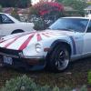
JustinOlson Posted August 22, 2008 Share Posted August 22, 2008 I was under my Z playing with the suspension and was wondering if anyone had raised the lower control arm mounting points for extremely lowered Z cars in the rear? I know Terry lowered the outer mounting point on the strut tube to help level out the control arms on his Z. I'd like to see what it would be like to raise the rear diff and rear control arm inner mounts to get things back level on very lower Zs. Picture of Jay Hitchcocks extremely lowered Z with 18" CCWs (I think he's running a 335/30-18 with a 26" overall diameter). Regards, Justin Quote Link to comment Share on other sites More sharing options...
JMortensen Posted August 22, 2008 Share Posted August 22, 2008 The problem is that the front pivots are already notched into part of the frame. You'd have to rework the floor in the back if you wanted the pivots more than about an inch higher than stock in the front. Raising the rear would be simple, just make shorter uprights. Quote Link to comment Share on other sites More sharing options...
JustinOlson Posted August 22, 2008 Author Share Posted August 22, 2008 I realize the front is where the majority of the work is. Is there anything wrong with raising these mounting points? I imagine that clearance would have to be adjusted between the control arm and the surround sheet metal much like you did Jon on your car. Justin Quote Link to comment Share on other sites More sharing options...
tube80z Posted August 22, 2008 Share Posted August 22, 2008 Another option is to shift the mounting points back a bit to gain clearance. You're still going to have to do some work in the sheet metal probably but you could change the inner mounts to rod ends and use custom arms as in a couple of the other threads. The benefit of doing all this is you have the ability to start playing with squat. You do need to be careful when you raise the inner point you don't foul the half shafts. The car above may look cool but that rear suspension isn't going to work very well. If you're flat statically you may find the having the arms drop a little as above helps to put the power down. At least that's one things we've seen from the cars setup this way. Another option is to change the outer as Terry did in yet another thread. Lots and lots of options -- pick wisely Cary Quote Link to comment Share on other sites More sharing options...
JustinOlson Posted August 23, 2008 Author Share Posted August 23, 2008 Will I sacrifice strength of the lower control arm by making the forward swept angle shallower (bringing the front mounting point back)?? Justin Quote Link to comment Share on other sites More sharing options...
WizardBlack Posted August 23, 2008 Share Posted August 23, 2008 Indeed, you'd need something with a substantial cutout for the axles. Quote Link to comment Share on other sites More sharing options...
WizardBlack Posted August 23, 2008 Share Posted August 23, 2008 I was under my Z playing with the suspension and was wondering if anyone had raised the lower control arm mounting points for extremely lowered Z cars in the rear? I know Terry lowered the outer mounting point on the strut tube to help level out the control arms on his Z. I'd like to see what it would be like to raise the rear diff and rear control arm inner mounts to get things back level on very lower Zs. Picture of Jay Hitchcocks extremely lowered Z with 18" CCWs (I think he's running a 335/30-18 with a 26" overall diameter). Regards, Justin Got more pics? Quote Link to comment Share on other sites More sharing options...
Administrators RTz Posted August 23, 2008 Administrators Share Posted August 23, 2008 Got more pics? How about a video?... [/threadjack] Quote Link to comment Share on other sites More sharing options...
tube80z Posted August 23, 2008 Share Posted August 23, 2008 Will I sacrifice strength of the lower control arm by making the forward swept angle shallower (bringing the front mounting point back)?? Not sure, but I would at least make sure to keep the same front to rear distance. What I was looking at doing was moving both points back a little to make it possible to raise them up a bit. Cary Quote Link to comment Share on other sites More sharing options...
NCchris Posted August 24, 2008 Share Posted August 24, 2008 Justin, http://www.arizonazcar.com/newparts.html check it out....... Quote Link to comment Share on other sites More sharing options...
JMortensen Posted August 24, 2008 Share Posted August 24, 2008 Justin, http://www.arizonazcar.com/newparts.html check it out....... Ah yes. The infamous "dual inner pivot" rear control arm. Quote Link to comment Share on other sites More sharing options...
74_5.0L_Z Posted August 24, 2008 Share Posted August 24, 2008 Wouldn't it be a whole lot easier to lower the outer pivot (ala BlueOvalZ) than to raise the inner. Oops, Cary already mentioned that. Quote Link to comment Share on other sites More sharing options...
jt1 Posted August 24, 2008 Share Posted August 24, 2008 Whatever you do to the forward LCA mount has to be strong. Most of the force that accelerates the car is transferred to the chassis thru the FLCA mount. jt Quote Link to comment Share on other sites More sharing options...
blueovalz Posted August 24, 2008 Share Posted August 24, 2008 Ah yes. The infamous "dual inner pivot" rear control arm. .Take a look at the last photo. It appears some additional effort (and parts) may have been put into stablizing the tube somewhat from rotating? The lowering of the outter pivots was a neat project, but not one I would recommend. It took a lot of work, and very carefull fitting and proper welding because all the braking, lateral and longitudinal forces work on that area of the strut. If I had to do it over again, I'd do it in a modular theme in which a fully fabricated extension is bolted onto the strut using the existing pin boss and whatever else is rigid. Quote Link to comment Share on other sites More sharing options...
JMortensen Posted August 24, 2008 Share Posted August 24, 2008 .Take a look at the last photo. It appears some additional effort (and parts) may have been put into stablizing the tube somewhat from rotating? If I'm not mistaken that looks like a shortnose R200 front diff mount that is clamped to the inner pivot thing. It would appear from the picture that this diff mount has two separate pieces that clamp to the control arm and there is no top piece or anything else that manages the thousands of lbs of lift from the front of the diff. From that picture it looks like he's taken a horrible situation and managed to make it quite a bit worse. Someone pinch me, I have to be dreaming... Quote Link to comment Share on other sites More sharing options...
blueovalz Posted August 25, 2008 Share Posted August 25, 2008 AND...and poly mounts in the mustache bar. Pinch you twice? But then, perhaps the tube's bushings will mitigate that issue To put a positive light on this, if the tube was of sufficient wall thickness, and the 4 piece front differential mount was remachined to be 3 pieces (single cross piece with 2 caps), then it may not be such a bad solution. Check my logic here. Assuming 300 lb/ft of torque, and for argument's sake, and the front mount is exactly 1 foot from the axle centerline. If you consider the ring gear as immovable, and the average distance from the pinion centerline to the ring gear is say...1.5", then you should have an 8:1 ratio of torque causing the pinion gear to crawl up the ring gear with 2400 lbs of force. If the ring gear is 8" in diameter, and the differential front mount was 12" forward of the axle, then this would be a 4" to 12" ratio, or 1:3. So then the 2400 lbs would be reduced to 800 lbs on the differential mount itself? A longer differential case would have less force on the mount than a shorter case, but obviously the rear mount will have an affect on this rationale....why do I do this to myself? Quote Link to comment Share on other sites More sharing options...
JMortensen Posted August 25, 2008 Share Posted August 25, 2008 That would be better, but there would still have a myriad of other issues. If this was a welded cradle in the front with a diff mount built in, I'd say it's better, but would prefer the mount be on the top like Ron's diff mount. The tubes are still kept from rotating with a set screw it seems, and there is still nothing preventing the tubes from sliding fore and aft (maybe the 1/4" set screw does double duty there). As to the control arms themselves, we still have Dave advertising that you can center the wheel in the wheel well, when we know this puts a hell of a bind on the strut itself, and we still have the critical spacing between the forward and rear outer rod ends, and the fact that adjusting them to change the toe changes the critical distance. It's still a bad idea bonanza! Quote Link to comment Share on other sites More sharing options...
260DET Posted August 25, 2008 Share Posted August 25, 2008 Always found it interesting that raising the front static roll center to compensate for lowering the car is a common practice, yet no account of the effect of lowering on the rear roll center was usually taken. Its my understanding that the rear center should be a few inches higher than the front so lowering as above messes with that idea. I suspect that a lowered S30 could be made to handle better on a circuit with its roll centers adjusted as above but never got round to it myself. EG it would not require such heavy ARB's as some seem to find necessary and so avoid the substantial weight transfer that heavy ARB's contribute to outside wheel loads. Quote Link to comment Share on other sites More sharing options...
Mike Mileski Posted August 28, 2008 Share Posted August 28, 2008 Here's what I'm working on for my set of rear control arms. The end pieces of the long link at the top are the same OD as that of the stock, or poly, bushing and fit perfectly into the cradles that normally hold the stock bushing. The ears that are welded to these end pieces accept the stock bolts normally used to bolt the little U brackets over the bushing. These end pieces are held in place by 3/4-16 Grade 8 bolts that go through the big 3/4" rod ends and thread 2" into the main long tube. Once everything is tightened up and bolted in place, it allows the main arm to pivot on the two heavy duty 3/4" rod ends. I still need to fit, notch and weld the three additional pieces of tubing, which I've tried to show by the black electricians tape and approximate the final look. The one "floating" outer link is right hand / left hand adjustable and attaches to the clevis as shown. The other one will also be adjustable via the hex portion of an inner threaded sleeve that extends through the short piece of 1.5" OD tube. All of the tubing used to construct the arm is 1" OD except for that one short piece with the threaded adjuster. I'll take some finished pics to post when they're finished and guarantee that they will look better with real tubing and some powder coating. Mike Mileski Tucson, AZ Quote Link to comment Share on other sites More sharing options...
JustinOlson Posted August 28, 2008 Author Share Posted August 28, 2008 That is a very cool project! Good work so far!! Are you raising the inner pivot points? Justin Quote Link to comment Share on other sites More sharing options...
Recommended Posts
Join the conversation
You can post now and register later. If you have an account, sign in now to post with your account.