240hoke Posted September 27, 2009 Share Posted September 27, 2009 Hey Guys, I've really been wanting to get the rear end of my car adjustable and squared up. After weighing the options out there I wasn't to happy with what was available. Ive starting working on my own rear LCA design. Similiar to what Myron build for his car I plan to use a classic A-Arm design. One of the main benifits of the a-arms is the use of a toe link which prevents binding with toe adjustment. A large drawback however is that all the acceleration forces go through the single Rod end at the front, however with proper sized tubing and high quality rod ends this isn't a problem. Here is what I have come up with so far: - The arm itself will be JIG constructed with 4130 Chromo Tube (TIG'd and stress relieved) - Rod ends will be QA1 5/8" Heaby Duty Alloy (Radial UTS 40kips) - Custom double adjuster for easy on car adjustability I have done some rough load calculations and found that the Heavy duty alloy rod ends are mandatory for a A-arm design. Even with a H-arms standard rod ends would be borderline. I am still working on the load calculations to determine the exact wall thickness for the tubing. Youll notice the lack of endlink mount too, Right now Im looking at mounting the end link to an outboard gusset. I am hoping to make a rod end swaybar endlink with adapters to work with the horizontal sway bar holes. The end link location will be adjustable fore and aft to ensure the link is perpindicular with the ground no matter what setup you are running. More then likely Ill stick with Urethane inner bushing to keep some compliance in the setup. I wanted to throw this out there and see what tips and advice ya'll might have. I plan on making a few prototype sets and testing them out for a while and then I will more then likely start producing them since I will have a jig ready to roll. Quote Link to comment Share on other sites More sharing options...
JMortensen Posted September 28, 2009 Share Posted September 28, 2009 Why a clevis on the toe link where it connects to the arm? That turns the A arm and toe link into a very weak H-Arm. I'd rather see a clevis on the arm itself for a rod end mounted in double shear. I'd use 3/4" rod ends with 5/8" holes, as they're a lot stronger. Finally I really do think there is a big benefit to the solid rod end being installed in the back. Also the gussets should be taco style. Flat gussets are so 1980's. Quote Link to comment Share on other sites More sharing options...
240hoke Posted September 28, 2009 Author Share Posted September 28, 2009 Hey Jon, Thanks for your input, just the kinda of feedback i was looking for. I'd use 3/4" rod ends with 5/8" holes, as they're a lot strongerI have looked at the 3/4 shank rod ends and actually the critical area seems to be in the metal around the rod ends. The 5/8" HD rod ends have a larger outer diameter and are rated exactly the same as the 3/4 shank ones. I originally drew it with 3/4 shank but when I found the HD 5/8" I switched back, less clutter, less weight, same price. I'd use 3/4" rod ends with 5/8" holes, as they're a lot strongerI should note that the outboard rod ends are not solid as they are drawn, I have just drawn the critical dimensions for modeling purposes so they appear solid, maybe this lead to some confusion? If they were solid I agree it would be a terrible design. The Clevis acts exactly the same as a solid rod end would; it allows the toe link to swing side to side but not cock when adjusted like a standard rod end does. I have initially choosen to use the clevis because its is easier to fabricate the mounts for it, they will both be similar strength and place the bolt in double shear. The clevis is a 5/8" shank with a 1/2" thru holes, a 1/2" grade 8 bolt in double shear is rated much higher then the outboard rod ends. One advantage of using an inboard solid rod end is that it would spread the load out on the tube. Definitly something to think about. Also the gussets should be taco style. Flat gussets are so 1980's. I definitely like the taco guessets, Ill switch over to that in the final design. Im just trying to move out of the 70's anyway 10 years is a good step forward Quote Link to comment Share on other sites More sharing options...
JMortensen Posted September 28, 2009 Share Posted September 28, 2009 I have looked at the 3/4 shank rod ends and actually the critical area is in the metal around the rod ends. The 5/8" HD rod ends have a larger outer diameter and are rated exactly the same as the 3/4 shank ones. I originally drew it with 3/4 shank but when I found the HD 5/8" I switched back, less clutter, less weight, same price. So it sounds like the same thing I have but with a 5/8" shank. I guess that is 6 of one 1/2 dozen of the other if so. I honestly dont see where you are coming from here, the clevis acts exactly the same as a solid rod end would; it allows the toe link to swing side to side but not cock when adjusted like a standard rod end does. I have initially choosen to use the clevis because its is easier to fabricate the mounts for it, they will both be similar strength and place the bolt in double shear. The clevis is a 5/8" shank with a 1/2" thru holes, a 1/2" grade 8 bolt in double shear is rated much higher then the outboard rod ends. One advantage of using an inboard solid rod end is that it would spread the load out on the tube. Definitly something to think about. The clevis won't move freely with a bolt through it and tightened, unless you undersize the plate you're attaching it to. Also it doesn't allow any up/down motion, so any twist in the A arm will put a bending load on your toe link. Making it a rod end on the inside allows freedom of motion in every plane but in and out, and that's much preferable in this spot I think. I should also note that the outboard rod ends are not solid as they are drawn, I have just drawn the critical dimensions for modeling purposes so they appear solid, maybe this lead to some confusion? I figured those would be regular rod ends. Quote Link to comment Share on other sites More sharing options...
MoNkEyT88 Posted September 28, 2009 Share Posted September 28, 2009 Where are you going to mount the sway bar? Quote Link to comment Share on other sites More sharing options...
heavy85 Posted September 28, 2009 Share Posted September 28, 2009 Also on the toe-link attachment I would make it 'taco' style to distribute stress to the strong part of the A-arm tube. This same theory applies to why 'tacos' would be preferred for all the gusseting. Having it go into the middle of the tube is less stiff/strong than attaching to the top and bottom. For the toe link attachment you could start with a rectangular tube instead of a flat plate, notch one side around the A-arm tube at the appropriate angle, drill a vertical hole for a rod end and Bob's your uncle. I look forward to seeing your calculations so I can steal the tube thicknesses if I ever build my own. Cameron Quote Link to comment Share on other sites More sharing options...
240hoke Posted September 28, 2009 Author Share Posted September 28, 2009 The clevis won't move freely with a bolt through it and tightened, unless you undersize the plate you're attaching it to. Also it doesn't allow any up/down motion, so any twist in the A arm will put a bending load on your toe link. Making it a rod end on the inside allows freedom of motion in every plane but in and out, and that's much preferable in this spot I think.Nor will a solid rod end, the toe link also only needs to move when adjusting. I used a clevis to l help limit twisting, which hopefully there wont be much of regardless. Where are you going to mount the sway bar?Addressed in first post. Also on the toe-link attachment I would make it 'taco' style to distribute stress to the strong part of the A-arm tube. This same theory applies to why 'tacos' would be preferred for all the gusseting. Having it go into the middle of the tube is less stiff/strong than attaching to the top and bottom. For the toe link attachment you could start with a rectangular tube instead of a flat plate, notch one side around the A-arm tube at the appropriate angle, drill a vertical hole for a rod end and Bob's your uncle. I look forward to seeing your calculations so I can steal the tube thicknesses if I ever build my own.Doubly note, and I completely agree. Will probably move to a solid rear heim, to help distribute lateral toe link loads and use taco guessets as Jon suggested. I was thinking purely from an ease of fabrication stand point , not my goal here. I look forward to seeing your calculations so I can steal the tube thicknesses if I ever build my own.I might have to keep these a secret then...j/k. Hopefully ill have time this week to crunch some numbers. I was doing rough calcs for the rod ends with a 2500lb car 1g forward, 1.5g lateral. Keep the criticism's and suggestions coming! Quote Link to comment Share on other sites More sharing options...
JMortensen Posted September 28, 2009 Share Posted September 28, 2009 Nor will a solid rod end, the toe link also only needs to move when adjusting. I used a clevis to l help limit twisting, which hopefully there wont be much of regardless. But a bearing rod end will, which is what I was suggesting. You're assuming no flex in the control arm and a perfectly perpendicular relationship between the strut and the arm. Anything else is going to stress the arm and put a side load on the strut. Have you read this thread? http://forums.hybridz.org/showthread.php?t=129154&highlight Quote Link to comment Share on other sites More sharing options...
240hoke Posted September 28, 2009 Author Share Posted September 28, 2009 No I havent, thanks for the link looks like it will be a good read. Quote Link to comment Share on other sites More sharing options...
cygnusx1 Posted September 28, 2009 Share Posted September 28, 2009 Austin, since I am laid off and need to keep my Solidworks fingers exercised, I came up with a concept LCA. It's a bit "mechanical" but that's the M.E. in me coming out. It retains the twist rigidity of a solid arm but allows for simple toe adjustment. Caster can be easily done with spacers on the outboard end, and camber could be done by bolting the outboard plate on instead of welding, allowing the use of shims/spacers to lenghten the outer section. It's only rev1 and totally a "freehand" concept that might spark some other ideas. There is a lot of room for improvement and simplification. The two holes in the inner triangle are clearance on top and tapped on the bottom to clamp the swinging arm. The swinging arm has a radius slot that allows the angle to be changed. All loads are transferred through the kingpin and the outer plate fits snugly to the inner arm section so that it can't twist in the horizontal plane. Quote Link to comment Share on other sites More sharing options...
260DET Posted September 28, 2009 Share Posted September 28, 2009 Also on the toe-link attachment I would make it 'taco' style to distribute stress to the strong part of the A-arm tube. This same theory applies to why 'tacos' would be preferred for all the gusseting. Having it go into the middle of the tube is less stiff/strong than attaching to the top and bottom. For the toe link attachment you could start with a rectangular tube instead of a flat plate, notch one side around the A-arm tube at the appropriate angle, drill a vertical hole for a rod end and Bob's your uncle. I look forward to seeing your calculations so I can steal the tube thicknesses if I ever build my own. Cameron Yeh I used square tube for the reasons you mention with my Mk 2 arms, wrap around double gussets with the round tube Mk 1 versions. Taco style With square tube its easy to cut a piece of tube on an angle and fit and weld it into the V where two pieces meet, instead of using gussets. Quote Link to comment Share on other sites More sharing options...
240hoke Posted September 28, 2009 Author Share Posted September 28, 2009 I like your idea Dave but several things come to mind right off hand. 1.) Extremely hard to make fine adjustments on car at the alignment rack 2.) Weight, Granted you can take ALOT out of what you have drawn 3.) All the solid machined components are going to be expensive especially at the tolerances you will need to make it rigid and not rattle around 4.) Wear, Kingpin and slot will take alot of wear quick more then likely and then the arm will be ruined 5.) Im not sure I see the advantage of where you have the pivot point, unless you can put it inline with the strut its still going to slightly miss align the strut like the toe link When you model tube assemblies like that are you building each tube as an assembly or merging several extrudes and then separating them? Ive swtich over to Pro-E and am am pretty noob with tube work....so this is giving me some practice. I am definitly going to move the front outboard rod end forward to allow the use of spacers to shim the strut forward and backward to ensure that it can be aligned properly. I am of the opinion that LCA was never ment to handle twist or moment loading, nor will it ever do a good job of it. I think to really get things "right" a entire new suspension design is in order. Bolt in double wishbone setup....anybody want to hop on this Also on the taco gussets, I obviously see the advantage from a stress standpoint. But I also think they came into being because of the use of lightweight thin wall tubing. Depending on the tubing thickness and the stresses in the structure, I would have to argue that flat gussets still have there place in some circumstances (purely from a functional and manufacturing standpoint, not from a best standpoint) Right now I need to determine whether I want to focus on a lightweight and expensive arm, or a slightly heavier easier arm which would be easier to produce and much more affordable. This will all be decided after stress calcs as 1020 may prove actually be more practical. I personally don't compete with my car and it is mainly driven on the street, so weight is not a huge issue for me. How much is to worth to you guys? My biggest goal is easy on car adjustment and easy installation and removal. Quote Link to comment Share on other sites More sharing options...
JMortensen Posted September 28, 2009 Share Posted September 28, 2009 I am definitly going to move the front outboard rod end forward to allow the use of spacers to shim the strut forward and backward to ensure that it can be aligned properly. I am of the opinion that LCA was never ment to handle twist or moment loading, nor will it ever do a good job of it. I think to really get things "right" a entire new suspension design is in order. Bolt in double wishbone setup....anybody want to hop on this Agreed, so why not make it so that it doesn't have to handle those loads. If you read the section in Milliken and Milliken's book, it talks about how any twist in the arm loads the strut. So why not make it so that it CAN'T load the strut my putting the toe adjuster on bearings at both ends. Basically what I'm saying is that A arm and toe link > H arm. Double wishbone is a nice idea, but I think the argument against it is one of packaging in that unless you want to really cut up the back end of the car you'll probably end up with a really short upper which means you'll get more camber change under suspension movement. Also one has to consider the ultimate speed advantage of the one over the other. Has anyone gone faster with double wishbone in the back of a Z? Surely someone has tried it before. If not, you may be the brave guy who gets to prove your theory to the rest of us, but likely not since you're describing yourself as "mainly a street driver". On the street I don't think the effect is worth the hassle. On the track, then I'd give it a doubtful maybe. As to the taco gussets, they don't really have to be taco gussets. You could also just weld your flat gussets tangentially to the tube instead of right down the middle, with one on each side. Put a concave curve on the part that hangs out between the two tubes, just like they do on many motorcycles and bicycles. Quote Link to comment Share on other sites More sharing options...
240hoke Posted September 28, 2009 Author Share Posted September 28, 2009 Agreed Jon, I have no plans for a double wish bone setup! I was suggesting somebody else come up with it Im about to get into Milliken, it happens to be sitting right beside me. I got the book and the companion workbook and have been trying to go through it. It is definitly a sweet reference. The more I think about the taco gussets they really wouldn't be bad to fabricate, especially if I am making a production run. Modeling them as sheetmetal and then getting them water jet would be easy enough. Might do double flat plates for the prototypes, like you suggest. Quote Link to comment Share on other sites More sharing options...
MONZTER Posted September 29, 2009 Share Posted September 29, 2009 (edited) Taco gussets are pretty simple to make. Use some paper to make a template or unfold something in Solidworks. Band saw out the flat shape and mark you start and stop bend lines. Get a pc of round steel the inside diameter of the gusset and clamp it in a mill vise with the flat plate at your bend line. Use a dead blow hammer and roll it over. Once you have it past 90 degrees pinch both side around the round steel rod and again dead blow it to shape. A little fine trimming with a Dynafile and your set. Don’t forget the vent holes inside the gussets Click the picture to super size them Edited September 29, 2009 by MONZTER Quote Link to comment Share on other sites More sharing options...
240hoke Posted September 29, 2009 Author Share Posted September 29, 2009 As always beautiful work Monzter! What is the first arm for? Quote Link to comment Share on other sites More sharing options...
MONZTER Posted September 29, 2009 Share Posted September 29, 2009 The first ones are for my front, using an inner tie rod end for the rear pivot. The front rod end allows for bump steer tuning along with the custom tie rods Quote Link to comment Share on other sites More sharing options...
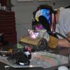
Mike Mileski Posted October 1, 2009 Share Posted October 1, 2009 Here's mine. Mike Mileski Tucson, AZ Quote Link to comment Share on other sites More sharing options...
proxlamus© Posted October 1, 2009 Share Posted October 1, 2009 my God monster.. i would love to wonder around shamelessly in your garage for hours and lay underneath your car and eat popcorn... what part on your Z haven't you touched and modified and improved?! Quote Link to comment Share on other sites More sharing options...
heavy85 Posted October 2, 2009 Share Posted October 2, 2009 Here's mine. Mike Mileski Tucson, AZ What kind of joint is that for the toe link? Cameron Quote Link to comment Share on other sites More sharing options...
Recommended Posts
Join the conversation
You can post now and register later. If you have an account, sign in now to post with your account.