-
Member Statistics
33427
Total Members5167
Most Online
All Activity
- Today
-

Nissan L-Series Cylinder Head Flow Bench Testing and Development
DuffyMahoney replied to MONZTER's topic in Nissan L6 Forum
Super cool stuff -
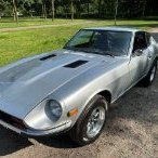 I think both chassis are doable if you can get the engineering of the rear engine layout to work. If the rear engine layout doesn’t work out great then I suggest looking at a mid-engine layout in a 2+2. As a bonus the 2+2 is usually a lot cheaper as they are less desirable, at least here in Europe. I would suggest starting with a really good 3D model or scan of a S30 Z (model and year doesn’t matter to much) and try and work out the engine and transmission placement as much as possible while leaving the rear taillight panels in place. The rest doesn’t matter for now. This is an ambitious project but I’m really excited to see how you’ll handle it.
-

Nissan L-Series Cylinder Head Flow Bench Testing and Development
MONZTER replied to MONZTER's topic in Nissan L6 Forum
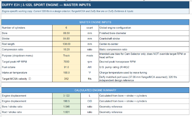
Duffy thanks, this lets me complete most of the analysis. Lets have a look at the basics first, I've adjusted details too better match your set up. I've also set it to track given your cam choice as it is better suited for higher RPM power and the resultant port sizing based on what you told me (Intake) Exhaust Intake Valve Exhaust valve Bowls so far all your specs align quite nicely with the workbook prediction for an optimal engine for trackish use with a 7000rpm peak power band. Ill get you runner length specs tomorrow and simulated dyno run numbers
-

5 cylinder GM ATLAS 3700 build with 4L60e transmission
A to Z replied to A to Z's topic in Other Engines
11-05-2026. CHANGE OF PLANS. I am no longer going with the 4L60e automatic transmission. I got a 5 speed AR5 manual transmission for this build. 62K original mile unit inbound. Just couldn't get excited about the auto no matter how modified I was going to build it. - Yesterday
-
Nissan L-Series Cylinder Head Flow Bench Testing and Development
DuffyMahoney replied to MONZTER's topic in Nissan L6 Forum
I am getting roughly 294.5mm +-.25mm total length from head flange to velocity stack bell. Throttles with the stacks are =153mm Phenolic spacers =10mm Intake = (harder to measure since it isn't straight at all, center of bore to center of bore is 131.5mm Stacks have a max opening of 80mm, they taper down to 50mm at the throttle opening, then 48mm throttle blades, then 45mm at the intake to throttle flange. Then slowly taper to the port size of 37.08
-
Thanks Mitchel, great tips, and the 250 GTO comparison made my day. Since the 2+2's extra length is in the doors, I'm thinking of using the shorter two-seater door and moving the rear wheel wells forward to take up that space. The car stays the same length. Does that sound doable from a chassis standpoint? I'll also take your advice on the radiators and fuel cell up front, water-to-air intercoolers, the front air dam and ducktail, and the cage. I'll check out Haltech too.
-
I could be wrong but I believe the extra length of the 2+2 sits mainly in the doors and middle of the car. That should make the rear wheel hub to rear body distance the same as a 2 door 280z. As the extra length of the 2+2 sits in front of the rear axle would it not be more beneficial to rotate the assembly and consider a mid-engine layout? I’m no 2+2 expert so I can only use my 2 seater ’77 280z as a reverence but this might give you more room to work with and eliminate the rear weight bias. Also consider adding some aerodynamic improvements to the car (especially the front) as the S30 Z’s naturally gain lift add speed. A front spoiler or air dam in combination with a ducktail spoiler should be enough for most Z’s. As for your other questions, if you brace the subframe good enough and also add a roll gage then I wouldn’t be that afraid of rear body twisting. Just extend the roll cage toward the rear and trinucleate the rear quarters. As for cooling I would keep the radiators in the front together with a good size fuel cell and use water to air intercoolers for the turbo’s as you still want to increase front weight. As for ECU’s it’s mainly up to (the tuners) preference, I personally like halltech as they have a lot of support and pre made aftermarket engine harnesses. But the most important thing is just doing what you really want to do and making your dream a reality. I really like the idea of this project and love the renderings, the front arches reminds me a bit of a 250 GTO.
-
Nissan L-Series Cylinder Head Flow Bench Testing and Development
MONZTER replied to MONZTER's topic in Nissan L6 Forum
Hi Duffy, I calculate it from seat to bell mouth end but I already know port length, so Intake runner length from Head flange to Throttle body. (I was guessing 110mm), TB Length of 88mm long, another guess, and 65mm velocity stacks a third guess, so it will be good to know exactly, thanks - Last week
-
Nissan L-Series Cylinder Head Flow Bench Testing and Development
DuffyMahoney replied to MONZTER's topic in Nissan L6 Forum
How would you like intake runner length? Total from the stacks to the head? Cam is .525" lift and duration of 240 @ .05 valve lift -
Thanks for the honest feedback, everyone. rturbo, flatout, I hear you on the weight bias. flatout, your packaging math is exactly what I needed. I'm planning to move the rear axle line forward with a shorter 2-seater door so the transaxle outputs line up and the halfshaft angles stay under 15°. That should pull more of the VR30 inside the wheelbase. I know it'll still be tail-heavy, so I'm planning a reinforced rear subframe, a cage, and coilovers tuned for it. On budget and experience, I'm going in eyes open and doing as much of the work myself as I can. Still hoping a 2+2 owner can share the hub-to-bumper measurement so I can firm up the numbers.
-
 That’s a fair point — I wouldn’t use this 1.5 mm Z-pipe as a primary header or turbo manifold either. The intended use is downstream custom exhaust routing, where the main problem is packaging around existing components rather than supporting the turbine or collector. In that position, 1.5 mm stainless is a very different application from a manifold seeing direct turbine heat, concentrated collector stress and repeated flange loading. The part is mainly useful where two pipe paths need to cross in a compact space. The printed junction gives a controlled internal divider and repeatable geometry, but it does not remove the need for proper support, purge welding and a good transition to the connecting tubes. I agree with you on the manifold side: 321 and a thicker wall make much more sense for long-term durability, especially around the collector and wastegate. For the Z-pipe, I would still treat the actual vehicle, heat exposure, unsupported span and hanger layout as the deciding factors rather than claiming that 1.5 mm works everywhere. Also agree on back-purging the manifold. Solar flux can be useful when purging is difficult, but I would not treat it as equivalent on a highly stressed turbo manifold. Fixture the flange during welding, control the heat input and check it flat afterwards — that is usually more important than the material debate alone. Your point about ceramic coating and heat shielding is also well taken. On a street or competition car, shielding the master cylinder, wiring and nearby components is often more valuable than relying on the coating to survive indefinitely at the collector.
-
Nissan L-Series Cylinder Head Flow Bench Testing and Development
MONZTER replied to MONZTER's topic in Nissan L6 Forum
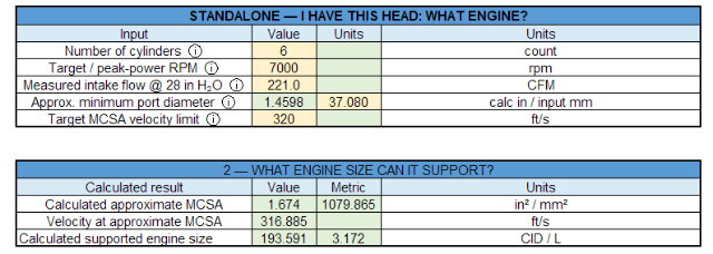
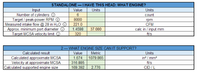
Duffy, that helps quite a bit. With the 37.08mm measurement being the equivalent diameter of your port opening, and that the flange is at or near the MCA, this changes my original calculations considerably. At 221 CFM, the calculated velocity through that opening drops from 356 ft/s with my original 35mm assumption to about 317 ft/s. That's almost exactly the 320 ft/s design target I was using for the L-series port. Using that new dimension, 221 CFM and a 7000 RPM peak horsepower target, my calculator comes up with a 3.172-liter engine. That's remarkably close to your actual 3.122L. So based on these assumptions, your displacement and intake port size appear to be pretty well matched for a 7000 RPM power peak. That's encouraging, especially considering your goal is a responsive street car rather than an 8000 RPM race engine. (At least what I think, for what its worth) I also did a rough port-volume calculation using your 45mm intake valve, an assumed 90% throat (40.5mm), an 8mm valve stem and the port centerline length from my E88 measurements. Assuming a gradual expansion from the flange toward the throat, I get approximately 124cc. That's only a geometric estimate, since we don't know the actual CSA progression or how Andy shaped the bowl and short side. We will use this number later to look at average port dimeter. What Andy is doing around that short-side turn is particularly interesting. If he's increasing the area and controlling the flow as it approaches the valve, that could help explain how he's getting those flow numbers without an excessively large flange opening / MCA. The one thing we still don't know is whether 37.08mm is actually the smallest section or whether the port necks down somewhere else. On L-series it is typically pretty close to the flange or about an inch in before the turn. But this new information makes your 221 CFM result much easier to reconcile with the port geometry and displacement, and it suggests your existing combination is reasonably close to the type of driving you described. The next step would be looking at your actual cam timing and intake runner length to see how well they're matched to that 7000 RPM target. We can do that in the rest of the tabs in my calculator Im working on But look when we put that head on a 2.8, A real ripper at 8k
-
Nissan L-Series Cylinder Head Flow Bench Testing and Development
DuffyMahoney replied to MONZTER's topic in Nissan L6 Forum
Looks like I am 37.08 This is the porting plate used to port match my intake to my head. Each aspect is port matched. Picture is prior to port matching, but shows the bends My porter (Andy) secret sauce is how he does his short bend, but I have no idea exactly how he does it. He seems to think the E31 can flow the best and is the best for "race engines" My car is a street car, so overall my goal is fun drive around and doing canyon driving.
-
Hey all, I'm mainly looking for 280Z 2+2 owners. Could someone measure from the rear hub center straight back to the rear body panel, and to the back of the bumper? I'm checking whether a rear-engine VR30 swap will fit, and I can't find this number anywhere. Please include your car's year and whether it's a US car. Thanks! Chibuike
-
 what is the final use of the combo? I wouldn't use 1.5mm a header/manifold for anything other than a dedicated drag car. I'm not a full time fabricator, but I've made a hand full of turbo manifolds with pretty good success for street cars over the years and my experience is I choose sch 10 pipe. (.109 or 2.75mm wall),But I choose 321 not 304. I have used SCH40 304 (~.140" or 3.5mm wall) but I don't think that is necessary unless your looking for extreme structure and weight is no concern. 321 seems to hold up better over time than 304. I've also probably gotten better at welding over the years but I have had two 304 manifolds end up cracking at the wastegate/collector after about 10 years and two 321 manifolds still holding strong. But i also have a handful of 304 that didn't crack. (at least not yet) I recently just made one for my Z out of 321 based off that information as well. As far as back purging. Id say for a manifold its 100% necessary. Its always a pain in the butt and I'm not sure what the best technique is. I do use solar flux regularly on larger diameter pipe like downpipes, turbo backs, or turbo cross overs for V8's with good success too. I feel those structures don't see quite the extreme stresses that a manifold does so i don't know if its as good as back purging. I would say if you can't backpurge then solar flux is the next best thing. as far as flange warping. you need to bolt it down to some sort of flat fixture for all welding. i've had a few that still bow a little and need to be sanded/milled flat but usually if you have it bolted down it holds up fairly well. After the turbo I use .065 (1.65mm) 304ss for the first elbow of the downpipe and have never had an issue. street, drag, drifting or road racing. back when i drifted i would cook ceramic coating off at the collector. I do think some people have good success with it tho so maybe an installation concern. but other wise i header wrap everything. and use a quality turbo heat blanket and heat sleeving around anything important. A master cylinder requires a shield for more organizations.
-
I've been working on stainless exhaust fabrication and wanted to compare notes with people who have actually built and lived with these parts, rather than just looking at datasheets. A few things I keep running into: 1. Wall thickness vs. heat cycling Going thinner saves weight and helps with tight packaging, but the weld HAZ seems to be where cracks start on parts that see repeated heat cycles. Where do you draw the line between 1.5 mm and 2.5 mm wall for a part that sits close to the turbo or manifold? 2. Back purge on SS304 Full purge gives a clean root, but it's awkward on complex multi-piece sections. Has anyone had good results with solar flux or a partial purge on the inside of joints that won't be visible? 3. Heat shielding Standalone shields vs. wrapping vs. coating — I'm interested in what actually holds up over a few seasons instead of what looks good on a fresh build. 4. Flange flatness after welding Distortion at the flange is the thing that quietly causes leaks and re-work. Do you fixture the flange before welding, machine it after, or both? I'm asking because I'd rather build around what people have actually seen fail than around theory. If you've got photos of failures or fixes, even better — those are more useful than opinions. Happy to share what I've run into on my side as well.
-
Nissan L-Series Cylinder Head Flow Bench Testing and Development
MONZTER replied to MONZTER's topic in Nissan L6 Forum
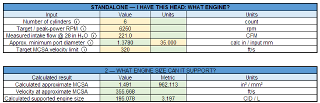
Duffy, thanks for the numbers. Let's see how this works out. My plan is to approach this two ways. First, "I have this cylinder head, what bottom end does it want?" Second, "I want to build this engine, what cylinder head do I need to support it?" Let's start with the first one. I've made a bunch of Excel calculators to help automate this process. Since I don't have all the details of your head, I'll need to make a few educated guesses. We have a 45mm intake valve and 221 CFM, which I'm treating as corrected to 28" H₂O. You mentioned roughly stock-sized ports, and this is where things get interesting. Flow numbers alone only tell part of the story. I'm going to assume a 7000 RPM peak horsepower target and a 35mm MCA (minimum cross-sectional area), expressed as an equivalent round diameter. The actual minimum might be at the flange or somewhere farther into the port. We won't know without measuring it. MCA is important because it determines the calculated average velocity through the smallest section of the port for a given airflow. For this example, I'm using 320 ft/s as a conservative flowbench-based design target. The L-series has a relatively low intake port with a sharp turn over the short-side radius. Picture a race car going around a track. You can carry plenty of speed down the straight, but enter a tight corner too fast and you're going to have problems making the turn. A modern high-port motorcycle head with a straighter approach to the valve might tolerate 350–360 ft/s. These are design guidelines, not hard limits. Port geometry and flow stability ultimately determine what's acceptable. Also, these are steady-flowbench-based calculations, not instantaneous velocities in a running engine. Dynamic sizing methods use piston demand and RPM and can produce considerably higher numbers. We've used approximately 613 ft/s as a dynamic design reference, but that's not a direct conversion from 320 ft/s. First example: 7000 RPM and 320 ft/s design target. The calculator gives us a 2.854-liter engine. Is that correct? Maybe, maybe not. It depends on what you're building. With our assumed 35mm MCA and a conservative 320 ft/s design target, the calculator suggests approximately 2.85L as a starting point for a 7000-RPM power peak. Notice the calculated velocity at MCA is 355.7 ft/s. That's based on the head's reported 221 CFM through our assumed 35mm minimum area. It's not a measured local velocity. The calculator is actually sizing this engine around approximately 199 CFM of required flow, corresponding to our 320 ft/s target. The head's full reported flow capacity remains 221 CFM. Now let's increase our design velocity target to 350 ft/s. Now we get a 3.122-liter engine. Same head, same assumed port size, same 221 CFM and the same 7000-RPM target. The difference is that we're allowing a higher calculated velocity at the engine's required airflow, approximately 217.5 CFM. But can this particular port support that demand efficiently? That's the question. If the airflow becomes unstable, especially around the short-side turn, cylinder filling may stop improving as RPM increases. This is where an engine can start running out of steam earlier than expected. A 3.1 or 3.2-liter engine needs more than a good peak CFM number if you expect it to keep making power at high RPM. The port needs the correct area, shape and flow characteristics to support that demand. OK, one more. Back to 320 ft/s, but lower peak horsepower RPM to 6250. Now we're at 3.197 liters. Nothing about the head changed. We're simply asking it to support peak horsepower at a lower RPM, where a larger engine can operate with less airflow demand per unit of time than it would at 7000 RPM. Here's how the three examples compare: The required-flow values come from the workbook's sizing model, not measurements of the running engine. Notice that 355.7 ft/s never changes. It's calculated from the same 221 CFM and 35mm MCA in every example. What changes is the engine's calculated airflow requirement at its target RPM. So what's my point? Flow numbers alone don't tell you how much power an engine will make or where it will make it. You need the right combination of airflow capacity, port area, displacement and RPM. None of these combinations is necessarily bad. They're just different engines that need different supporting components. A smaller displacement with a longer-duration cam might be happier running higher RPM. A larger displacement might make a better street engine, producing strong torque and reaching peak power sooner. Each would need its cam timing, intake runner length and exhaust system matched to the intended powerband. The mistake is assuming you can have everything simply by adding displacement, camshaft and RPM without considering airflow and velocity. This is why I think people need to be clear with their engine builder about what they actually want the engine to do, then select the components to support that goal. Getting back to your head, there's another important part of this. MCA is the smallest cross-sectional area anywhere along the port. Average CSA is calculated from port volume divided by centerline length. They're different measurements and tell us different things. Let's say your E31 has a 35mm MCA at the flange. At 221 CFM, that calculates to 356 ft/s. But if the port opens up to 37mm before the short-side turn, the calculated average velocity at that larger section drops to 318 ft/s. That's a significant difference on a low-port L-series head where the air has to make a sharp turn. This is why we need to know not only the MCA, but where it's located and how the port area changes toward the valve. Even with lower average velocity, poor short-side geometry can still cause flow separation. Port volume is useful too. For reference, a cleaned-up E88 measured approximately 104cc, a welded E88 measured 111cc, and the PAMS JP geometry calculates to approximately 129cc. These represent quite different port sizes, although volume alone doesn't tell us where the restrictions are. Ideally, I'd like to know your actual MCA, its location, and the intake port volume. With those measurements, we can make a much better assessment of what your head can support instead of guessing from peak CFM alone. And that gets us away from the bigger-is-better mentality and toward building an engine where all the components actually work together. Next, we'll look at the second approach: "I want to build this engine, what cylinder head do I need to support it?"
-
I'll just add some things to consider. At the end of the day. if its what you really want and you have the facts and still follow thru then more power to you. A Porsche transaxle usually puts the axles 5-10" behind the bellhousing. so take that measurement into account and add any adapters needed to attach to the VR. Axles shouldn't really be more than 15º at the joints. so looking at the wheel centerline the trans outputs can be a max of ~3" forward the wheel centerline. Overall length of a VR is probably 30" (measure yours). My Z is about 32" from axle centerline to tail lights. So my math is showing the accessory drive/engine will be sticking out the back of the car by several inches to line the transmission up with the wheels with the MAX angle of the axles. Now to take that placement into consideration even if you build something around the back of the car to encapsulate the engine or extend the rear, the entire engine, accessories, bellhousing, flywheel, clutch, headers, exhaust, Turbos, intercoolers, etc will be BEHIND the rear axle. Google says a bar VR weighs 430 and almost 500 with turbos and intercoolers. so id estimate 600 behind the rear wheels that a normal Z doesn't have. Comparing to a front engine Z. The factory engine is mostly behind the front axle toward the center of the car. a 4 cyl or v6 would probably be completely behind the front axle. Porsche engine is probably 6-10 inches shorter than the VR. A well handing Porsche target 60% rear bias. stock z is around 50 to 52% on the nose Mid engine GT40 is 55-58% rear. C8 corvette is roughly 60% rear.
-
 The show stopper is that it's a terrible idea. The Z simply is not meant to be rear-engined. It also sounds like you intend to keep a lot of the factory chassis (as opposed to a space frame and custom suspension) and make use of the rear seats. Well, you're going to have some 400-500 extra pounds way out in the rear of the car, and the factory suspension setup is not designed to cope with that, certainly not the relatively flimsy structure they're attached to. You're likely going to need a full roll cage to stiffen the chassis, at which point you lose the use of the seats. I think you'd be better off buying a 996/7 with a blown engine and engine swapping that. They've spent 50 years refining the chassis to suit the typically poor rear-engine layout, and it has excellent suspension on top of that, plus rear seats. You're basically trying to reinvent the wheel here. On the other hand, a VR30 in a Z would likely be just about a front-mid engine layout and would perform well if set up correctly. Those are your two realistic paths to a successful outcome, depending upon whether you prefer to have a Z or rear-engined 911. I strongly suggest you rethink your intended project here. It doesn't sound like you've thought through all the problems you're going to create by relocating the engine, and it is going to be very difficult to get it to work correctly. jhm also brings up a good point. What is your budget?
-
Thanks, both of you, I appreciate the honest pushback. I know a rear-engine layout isn't the "optimal" choice on paper, and I've looked at front-engine and mid-engine versions of this car. I chose rear-engine on purpose because I want the car to feel 911-like: lots of traction out of corners and under braking, with the character that comes with that. A mid-engine layout would also eat the 2+2's rear seats, which is part of why I bought a 2+2. To keep the weight bias under control, the plan is to mount the VR30 as low as possible on a dry sump, push it as far forward as the transaxle allows, and put the radiators, battery and fuel cell up front. I'm also expecting to need wider rear tires and a suspension setup that's tuned for it. If anyone has real corner-weight numbers from rear-engine swaps, or tips on suspension geometry for a tail-heavy car, I'd love to hear them. And if I'm missing a showstopper, please tell me now before I start cutting.
-
280z 1jz track build from a pile of parts
flatout replied to flatout's topic in S30 Series - 240z, 260z, 280z
I am trying to get out one more time this year but the weather here in New England may say otherwise. Car has been good. a few minor tweaks here and there. I have about 650 street miles on it. Did get a tire puncture which is rough because the tire had 400 miles on it, I plugged it but I think I need to replace it if I'm going to race it because the internet says a plug wont hold with the heat of racing. I did get some photos sent to me from the event i did in September that i wanted to share.
-
 Wow, that's an ambitious build!! Do you have experience in this area? If you really want to pursue that kind of wild project, I'd love to follow it. In terms of driveability, you might not be happy with the results...due to the rearward weight distribution, as highlighted by the others. But it certainly sounds like a "SEMA-worthy" concept! Off the top of my head, I think your budget is likely off by an order of magnitude or two. 🙁
-
A front engine Z is pretty easy to get 50/50. An aluminum 4 cylinder swap Z is very easy to produce a rear heavy bias. Id expect the VR to also be ale to be rear bias. I can't see without adding a bunch of weight to the front, a real rear engine Z car would be like 70% or more on the rear which would not perform well in any discipline. Mid Engine has a fighting chance of being decent balance if you can engineer it to be.
-
Okay, don't do it. There are zero rear engined vehicles being produced today, other than the 911, which engineers at Porsche have stubbornly but successfully managed to develop into a good car. It would be one thing if you were wanting to do a mid engine swap, which the 2+2 chassis would give you more room for, but there is not a single reason I can think of why you would do this. You want the weight in the middle of the car, not at the very ends - research polar moment of inertia. I think you should stick to a front engine layout, as that is what the car was designed as. IMO, trying to turn a front engined car into a mid or rear-engined car makes no sense, and you're better off buying something rear-engined to begin with, and doing so it will likely produce a better result. Better to work with the factory design than against it. That said, if you want to reengineer the car, at least do something that makes sense, like a mid-engine. There's a good reason practically every modern super car is mid-engined and not rear-engined. You might provide some detail as to why you decided on a rear-engined swap to begin with, and what motivates you to take on such an extreme project. FYI, in the 20 years I've been on this site, I think I've come across exactly one mid-engine swap, which should tell you something about the nature of the project you want to take on. I think you might be better off building a car from scratch if you want a big fabrication and engineering project.
-
Hey all. I'm planning a pretty out-there build and want input from people who've cut up Zs before I start. The car: a 1975-78 280Z 2+2 (GS30, 2605 mm wheelbase), orange. Budget-minded: about $4k for the car and about $3k for the gearbox. The plan: a 911-style rear-engine layout. - Nissan VR30DDTT twin-turbo V6 mounted fully behind the rear axle on a dry sump, aiming for about 600 hp - Porsche 997 Turbo G97/50 6-speed transaxle converted to 2WD (a 996 G96/00 is the budget fallback), with 930/996 Turbo CV axles - A bolt-in cradle so the engine and gearbox drop out the bottom, plus a louvered top service lid - 288 GTO-style slotted quarter-window vents feeding the turbos - LED headlights in the stock buckets, flares, black wheels I've done 3D layout renders (attached). Questions: 1. Adapter: has anyone made or bought a VR30 to Porsche G50/G97 bellhousing adapter? Who would you go to? 2. Weight bias and handling: with that much weight behind the axle, where would you start on rear suspension geometry and spring rates for a street car? 3. Chassis: how would you strengthen the unibody and design the rear subframe/cradle so the rear doesn't twist? 4. Cooling: front radiators with long lines, or side/rear radiators? What has worked for you? 5. Wiring/ECU: what standalone ECU would you run on a VR30 (Haltech, Link, MoTeC, other)? 6. Precedent: has anyone actually done a rear-engine Z? Build threads would help a lot. Any "don't do it, here's why" feedback is welcome too. Thanks!








-
Who's Online 0 Members, 0 Anonymous, 817 Guests (See full list)
- There are no registered users currently online