240Z Turbo
-
Posts
1083 -
Joined
-
Last visited
-
Days Won
1
Content Type
Profiles
Forums
Blogs
Events
Gallery
Downloads
Store
Everything posted by 240Z Turbo
-
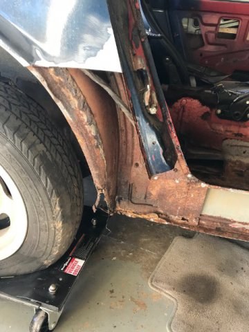
Prior to placing the car on the rotisserie, I have much work that needs to be done to ensure the car has enough structural rigidity. Specifically, the passenger side frame rail has significant rust where it joins the lower firewall. It is much easier to work on the car if its on a dolly/cart and I was going to purchase an auto body dolly from Redline for $600, but decided to just make one myself for ~$330. https://www.redlinestands.com/catalog/shop-equipment-c-327/automotive-c-327_328/body-cart-dolly-c-327_328_232/redline-engineering-restoration-auto-body-dolly-cart-p-2781 I had the local metal supermarket cut all the metal and ordered some heavy duty casters online. I'll pick up the metal tomorrow morning and the casters should arrive early next week so I'll post some pics of the cart once it's finished.
-
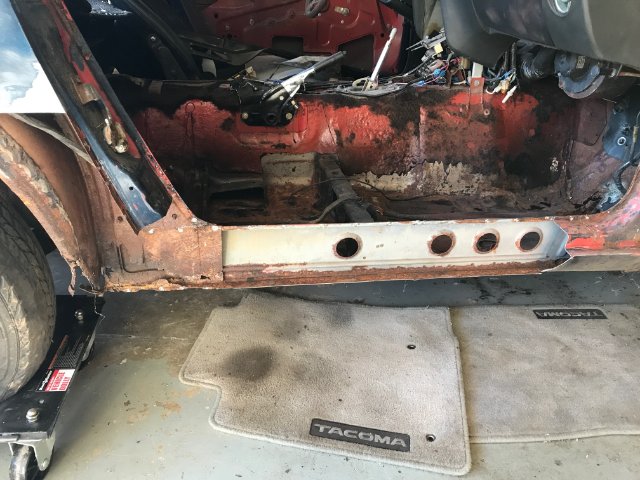
Today I ordered about $1500 worth of body panels from KF Vintage after getting a coupon to help offset shipping costs. This should allow me to fix everything on the passenger side excluding the front frame rail, which I need to assess it's shape when I get the engine out and the area sufficiently cleaned. PS - Dog leg, b-pillar, floor pan, inner rocker, outer rocker, front sandwiched rocker, firewall panel behind battery, entire battery tray area with battery tray DS - b-pillar, dog leg, outer rocker I also ordered a rotisserie today from the following company. I selected the "unibody brackets" for the rear and the "Redline Front Mopar Mounting Brackets" for the front. https://www.redlinestands.com/catalog/shop-equipment-c-327/automotive-c-327_328/rotisseries-c-327_328_212/redline-automotive-auto-restoration-rotisserie-p-2721 The parts from Tabco should arrive late next week rear quarters L/R outer wheel wells L/R rear panel slam
-
+1 old school
-
https://www.finjector.com/documents/4ec9f695740c8/0221604006_DataSheet_enUS_T6821266699.pdf
-
In case you're wondering what will power this 240Z, I have two options in my head. I am currently building a complete forged motor for my R35 GTR so I will have a stock VR38 that can be mated to a GM trans. The other option will be a 3L L28 with a single turbo S366 SXE (6668) on a custom small runner manifold with the LD28 intake manifold converted to fuel injection powered by an Electromotive Tech 3R mated to a GM automatic trans. My gut says old school, but plenty of time to think about it.
-
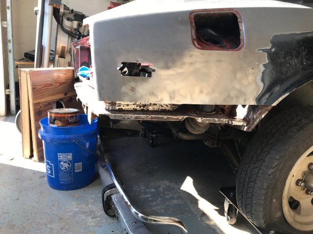
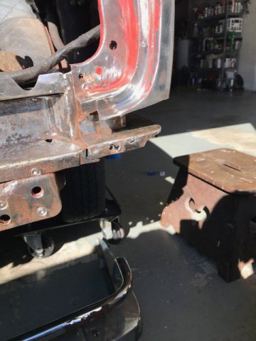
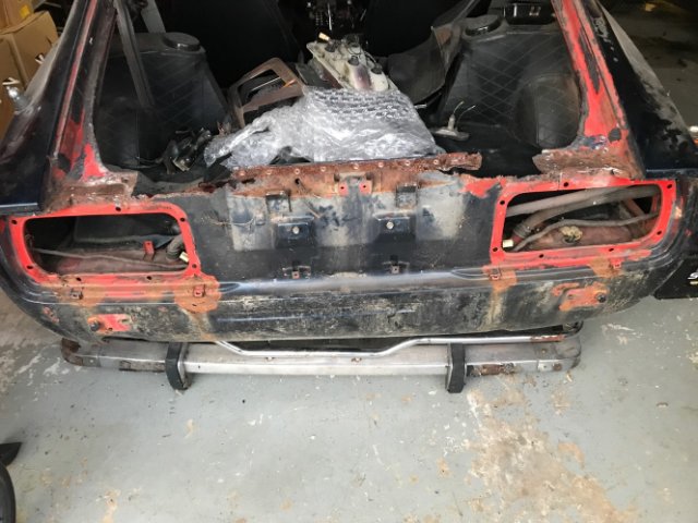
Still hacking away to see what needs to be replaced, but ordered a bunch of panels today from Tabco and have another order going to be made tomorrow from KF Vintage if they can get their act together on shipping costs. I also need to order a rotisserie in the near future once I get the car structurally sound where it can be supported. From the pic below you can see I need to replace the lower portion of the outer wheel well so I ordered new ones from Tabco. Unsure if I will replace the entire thing or just graft in the bad section. Didn't realize that damn wiring harness was under that panel so I cut through it with my saw. Sounds like I need to just install a complete new harness from Painless. The lower fender was in good order so it will be reused, but I had to remove because the inner piece the bolts the fuel filler hose has some rot that needs to be replaced. It also allows me to clean off all the surface rust and treat with POR. Kind of hard to see, but to the right of the filler hose by the wheel well there is a huge gaping hole from rust. I'll clean it up and weld in a patch panel. The inner and outer rocker as well as the front rocker will be replaced. Goes with out saying the floor pans are toast, but I will tackle those later once I get the rockers and rear quarter panels finished. One small hole on that back panel that I will patch and subsequently treat with POR. The surface to the left is pitted along the entire back of the car so instead of replacing I will just weld in 16g panels to beef it up.

-
I've been out of the scene since 2004, but purchased a 1971 240Z about 5 years ago and it's been sitting ever since. I finally got to the point that I wanted to start the restoration, which initiated last week. My 18yo son is helping me so it has been all good thus far. The plan is to do all the patch panel work myself along with the rust treatment and then have a body shop do the body work. I just want to make sure all of the rust is neutralized or removed and because I have all the necessary equipment to do this at my house, what the heck. Starting with the back of the car we removed the entire rear panel due to excessive rust. At this point I have 99% of the rust removed, but perhaps need to fabricate a few patch panels and decide on why type of rust neutralizer I should use along with the primer before welding the panel back to the car. I don't know how quickly all of this will get done, but it is my intent to steadily get the patch panel work finished.
-
You could perhaps just simply download the Bosch P100-T Coil PDF file and see they put out in excess of 100mJ spark energy.
-
Bosch P100-T coils are twice the spark energy as the R35 coils and about $100/coil.
-
Possible spark blow out. How small of a gap can I run
240Z Turbo replied to dpuma8's topic in Turbo / Supercharger
The boost fluctuation sounds like an issue with your duty cycle of the closed loop feedback on your boost controller assuming it is controlled by the MS. Without knowing how or what you use for a boost controller hard to exactly know what is happening. Regarding the dwell and voltage, the spark energy will be a function of both dwell time and battery voltage so a lot of systems have a 3D map to account for both variables. I run the Bosch P100-T coils in the link below and going from 14V down to 12V requires ~0.9ms of additional dwell to achieve equivalent spark energy. https://www.finjector.com/documents/4ec9f695740c8/0221604006_DataSheet_enUS_T6821266699.pdf From what I saw based on a quick check on the summit racing website, your coils will run in the 4.0ms range, but that is based on a calculator and not the actual coil performance from the manufacturer. You need to get the actual dwell times as a function of current draw and battery voltage to be accurate and then run them at a level sufficient based on the spark energy you desire. For the Bosch coils on the EVO I run them pretty hot at ~80mJ of spark energy based on a 7amp draw, but I also run ~35psi on a 9.5:1 motor. -
Possible spark blow out. How small of a gap can I run
240Z Turbo replied to dpuma8's topic in Turbo / Supercharger
Other's have asked what coils you are running and this is important since you run the MegaSquirt. You need to know the dwell time vs spark energy of your specific coil so you can input the appropriate dwell times in your software. Too little dwell can result in too little spark energy. Gapping down to 0.020" is not uncommon for high boost applications, but with a good coil setup no reason you can't run much higher. -
Need help diagnosing boost control issue
240Z Turbo replied to Zcardude's topic in Turbo / Supercharger
OK, good luck and do the intercooler when you can because you should be able to run 19-21psi on 93pump if you turbo is efficient at those pressure ratio's. -
Need help diagnosing boost control issue
240Z Turbo replied to Zcardude's topic in Turbo / Supercharger
EVO IX on pump gas -
Need help diagnosing boost control issue
240Z Turbo replied to Zcardude's topic in Turbo / Supercharger
Pin hole leaks are just a nuisance and likely don't affect your issue, but good to get them sealed. If you have boost creep then it would indicated you need to port the wastegate hole on the turbine housing to increase flow. Post up your actual log file and I will take a look using LogViewer and post the graphs. Regarding IAT, strive to be within 20F of ambient so if you are seeing 50F above ambient then likely your intercooler sucks. Garrett 24x12x3.5" core works exceptionally well and I see less than 20F over ambient at 34psi in the summer. -
GEN I GTX3582R vs S362 SX-E spool up on the street. The dyno does not load the engine as much so that affects the spool of the 68mm turbine wheel in the S362, but on the street I have countless logs showing it spools the same.
-
I know it is easier said than done, but you need to think about having someone fabricate a twinscroll manifold for your setup. The open scroll is great for a drag car, but in my experience it sucks for a street car because of spool. Below is an example on my EVO from back in 2011 when I was running a GTX3076r. I had a cast manifold using a T3 open scroll housing, 0.63 vs 0.82, and then I fabricated a twin scroll manifold and went to a1.06 a/r T4 twin scroll. The twin scroll crushed the open scroll in spool and made the same power on the topend, but killed the open scroll torque everywhere. I'll post a link below my new setup going from a GTX3582r (6262) to a BW S362 SX-E (6268) both T4 twin scroll. You'll be shocked the car spooled the same (on the street) and picked up 50hp@wheels...601hp@wheels on Shell 93 pump gas at 33psi! https://www.evolutionm.net/forums/evo-dyno-tuning-results/754630-gen-i-gtx3582r-vs-s362-sx-e-curt-brown-2-15l-pump-gas.html
-
Rule of thumb I use is multiple engine hp you want to support and multiply by 1.5 to get CFM needed. If you call K&N they will give you the CFM rating of a filter at standard pressure drop (can't remember what that drop is). So, if you want to support 500hp@engine then get a filter that flows 750cfm at standard pressure drop. I like running larger inlet filters and use a velocity stack. You can run a filter smaller than what I recommended, but this will only increase the pressure drop across the filter.
-
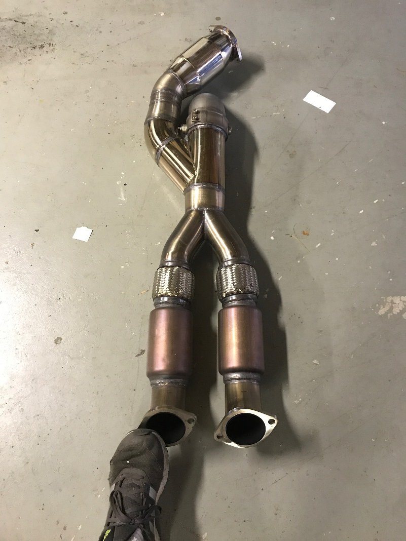
Primary cats are typically within 12" of the turbo, but secondary cats are usually much farther, perhaps 24-36" post turbo so putting it by the transmission should be ok. You can add the resonator either before or after the CAT so whichever position is most easy to integrate. On the GTR most people run the CATs on the midpipe and ditch the primary CATs, which is very similar to what you are proposing. On my GTR I used an XFORCE 100 cell CAT (XForce CAT12-350(100)) with my 3.5" piping, but they make an equivalent diameter CAT for 3" inlet/outlet. CAT only cost me ~5hp at ~825hp If you look at my CAT placement below it is considerably further back vs what you proposed and it seems to make a very noticeable difference in terms of sound and soot. I had to place it so far back so I could integrate a 4" dump valve. So now I can cruise around with the CAT and when I want all out power I can open the dump.
-
I think you will be fine either way, but if packaging is an issue you at least have piece of mind that 2.25" will support the necessary flow without excessive drag based on the guidelines provided by Corky Bell.
-
Just be careful as the holes in the front radiator support where you run the IC piping vary from year to year. Specifically, their location slightly changes depending on the year of your car. I learned this the hard way when I used to fabricate intercoolers for the Z.
-
In theory you want the post IC piping to be smaller and obviously, the pre intercooler piping would be larger. The air from the turbo to the intercooler will be less dense as it is significantly hotter and thereby requires more volume due to the decreased density. Once the charge goes through the intercooler it is cooler and therefore more dense requiring less piping size for a given mass of air. On the GTR we see the turbo to intercooler piping is 2.75" and intercooler to TB piping is mostly 2.50". With that said, I run 2.75" on my GTR for all piping, largely because I run a blow through MAF setup and I needed the larger piping on the post IC due to flow limitations. You don't want to go too big or you lose velocity in the pipe, which decreases throttle response and turbo response. If we assume you will want to support 400hp@flywheel then you need to flow ~600cfm. If you look at Corky Bell's book Maximum Boost, he says to keep charge velocity below 450fps to avoid excessive drag. A 2.5" pipe flowing 600cfm has a charge velocity of 293fps so well below the limit. A 2.25" pipe has a charge velocity of 362fps and 2.00" pipe has a charge velocity of 458fps. I would personally probably run 2.25" or 2.50" the whole way or you can mix and match based on the above density theory. Beyond 2.50" serves no purpose.
-
Your adapter for the wastegate looks great and you did a very nice job on the downpipe. Since your graph lines up almost exactly until you hit a certain RPM it would seem to indicate a restriction or a boost leak. What doesn't make sense is that you car won't make additional boost and we know the pressure is created because of the resistance to flow (restriction). A turbo speed sensor would definitely give you a better sense of these issues as well as the ability to measure EGBP before/after the turbo. I see you run the Tech 3, do you have any spare analogue inputs? Coming from my turbocharged 240Z that was running in the low 20's psi range it was a surprise that I was able to run so much boost on the EVO. 33-34psi is very common for the EVO on pump 93 and I have been running it this way for 4-5 years on the same engine. Keep in mind that I run -1deg of timing at peak torque and ramp it up to +8deg at redline so significantly lower timing than the L-series and my GTR. If you need a larger Tial housing just PM me and I will help you.
-
Just so you know I have my GTX3576r on the shelf and plan on running it when I start building the 71 240Z I purchased last year. Just saying that I don't perceive any issues with that turbo making power on an L-series motor. 500hp@wheels feels quick and 573@wheels pulls really strong, but no issue to control as the car is AWD. I have to say it is fun jamming the gears at that power level and revving the engine to 9K. When you do the 2-3 shift the car still pulls like a freight train in 3rd gear with no signs of slowing. Haven't run the GTX3582r past 34psi on pump 93 yet so I don't know how much more power it will make. My GTR put down ~705hp@wheels on 93 pump and ran 10.2@138 on the same pump gas tune, but running race gas. The GTR doesn't feel like its got 700hp@wheels because its a big/heavy car so it is deceptively smooth at that power level. Higher compression is nice and my EVO is 10:1 and most built GTR engines are in the 9:1 to 10:1 range even running pump 93. However, the fact that you run low compression is not necessarily bad and just look at TimZ and his 7.5:1 monster making in the 700hp@wheels range on E85. I think that was his old compression and suspect he still runs low compression, but he might chime in and correct me on that. If you want to understand the turbine restriction you can put a port on your exhaust manifold to measure Exhaust Gas Back Pressure before the turbo. Off the top of my head you want to be in the 1.5x boost range and if you measure post turbo on the downpipe you ideally want to be in the 1psi range, but slightly higher is likely also fine. Maybe you can post a log shot of your AFR, boost, and timing curves as a function of RPM. Also, the dyno results you posted, are they a direct before/after of old turbo vs new turbo with no other changes or did you make changes?
-
doubtful your surging on this turbo and not hearing or feeling it. The surge ports don't work well on that turbo and it would be audible as well as show up in the dyno graph. Having run the GTX3076r, GTX3576r, and GTX3582r(current) on my 2L EVO it definitely seems something is off with your setup. You would need to stick a speed sensor on the turbo to understand where you are on the map and it would also answer any doubt about surge. On the GTX3576r I made 505hp@wheels 33psi tapering to 31psi on 93 pump and 1.01ar Vband TS, 460hp@wheels 30psi on 93 pump and 1.06ar T4 TS, and 573hp@wheels 37psi tapering to 33psi on 110L and 1.01ar Vband TS. Since I log turbo speed the turbo was riding the choke line on the 573hp@wheel dyno pass so I gave it everything it had. The GTX3576r has the same turbine wheel as the old school 35r, but new billet compressor wheel so it actually flows more than the old 35r. This turbo flows ~64lbs/min so not gonna support 600hp@wheels on a accurate dyno unless your drivetrain loss is ~40hp. The fact that your pushing it past 22psi and not seeing a difference suggests you have a restriction in your system. Also, the .63a/r is small for a 2.8L so likely part of the problem and in general I don't like running open scroll because you sacrifice too much spool and gain little on the topend, but I do understand it is not an easy option to run a TS on the L28 due to lack of available manifolds. I saw ~400rpm loss in spool when going from 0.63 to 0.82 on the EVO, but gained ~35hp on the topend when I used to run an open scroll setup with the GTX3076r. Also, on my initial TS setup I lost no spool and gained ~50whp when swapping from the GTX3076r to the GTX3576r so turbine size does matter.
-
As a rule of thumb the filter flow, in cfm at standard pressure drop, should be ~1.5x the hp it is supporting. This means for 500hp you want a filter to flow 750cfm. That doesn't mean you can't make the same hp with a smaller filter, but you will have a higher pressure drop. Whether turbo or NA, pumps don't like restrictions on the suction side. K&N doesn't list flow numbers on their site, but if you call they will provide.