

RTz
-
Posts
2943 -
Joined
-
Last visited
-
Days Won
23
Content Type
Profiles
Forums
Blogs
Events
Gallery
Downloads
Store
Posts posted by RTz
-
-
As I understand it, MS doesn't limit current to the injector for some user-defined period and then switches to pulse width modulation (fancy way of saying it quickly switches the voltage on and off to limit the average current level).
Well, not exactly. PWM and current limiting are two independent actions.
Current limiting, with low Z injectors, keeps them from burning up. If you allowed them to draw full current, for more than a short period, they'd fry themselves. Whereas a high Z injector is 'self limiting', so to speak. The advantage of low Z, is a quicker response time... and once they're open, it takes little current to keep them open.
A simplified way to restate PWM is injector 'on time'. The longer time period it is 'on', the more fuel it flows, per injection event. Because MS uses a VE table, PWM is hidden in the background. However, the 'pulse-width' is the actual and *end* variable that dictates fuel volume, per 'squirt'.
-
just out of curiosity what kind of power numbers are each one of you guys making?
Jacking your own thread?

For clarification... in general, there won't be any appreciable power gains from brand to brand. There are some occasions where that statement isn't entirely true, but its somewhat rare (and specific). My point is... I believe it would be a mistake to choose one brand over another based on the 'perception' of peak HP.
-
I could use some advice and I have never used a forum before.
Welcome John,
Sounds like you care for your Z! You will find the answer to every question in our archives. Its easy to access and will have you asking questions you have yet to think of.
This will help you get started... http://forums.hybridz.org/showthread.php?p=813061#post813061
-
Second Tony's thoughts.
Also, with sequential injection, this means individual injector channels... which implies, at least at some point, individual cylinder trim is possible. It also implies that using those those channels for other features may eventually be possible... for example VQ35 VVT is PWM... and so is an injector channel.
...the trend in higher end systems is leaning towards channels rather than specific features.... do as you wish with them.
-
Globe,
Did you find any resolve?
-
You two should get a room
-
Do they have an American super sized version of that?
-
-
In my opinion, 160 is just too low.
Z-ya and I were just having this conversation, PM.
He's with you. I haven't bought into it... yet. Share your thoughts? (If this has already been hashed lemme know and I'll warm up the search engine).
-
I PM'd z-ya... hopefully we can get the 'secret' out of him
The brackets and Magnecor wires for the truck coils are officially available...
http://forums.hybridz.org/showpost.php?p=810283&postcount=2
http://forums.hybridz.org/showthread.php?t=120943&highlight=ls1+coils
-
PM z-ya. Not sure if he's actually running them on MS yet, but he's got it figured out. I believe Mobythevan has been playing with them as well.
As KTM mentioned, several of us are running them with Wolf3D. Haltech and Motec will also drive them.
-
Ignition Wiring Tip...
When wiring up a multi-coil ignition, I recommend wiring up the channels in the proper firing order.
For example, wiring 6 coils to an L6...
Wolf has 8 ignition channels, so you can wire 6 of those channels, one to each coil (and use the leftover two for auxiliary operations!). The L6 firing order is 1-5-3-6-2-4. I would normally wire it thusly...
Channel 1 to coil 1
Channel 2 to coil 5
Channel 3 to coil 3
Channel 4 to coil 6
Channel 5 to coil 2
Channel 6 to coil 4
To clarify, You can conceivably wire in any mixed up fashion that tickles your fancy because the configuration process allows you to fire channels in any order you wish. However, during the config. process, its much easier to keep it straight with the strategy I suggested, as it would look something like this...
0
1
2
3
4
5
instead of something like this....
0
4
2
5
1
3
Note: Wolf's channels begin with the number '0' in the software, hence the 0 thru 5 channel designation, adding to the difficulty of a proper configuration if you wire them out of sequence.
-
LOL
Hopefully the stickies will grow to the point of reasonable completion. It'll take time... bare with me!
-
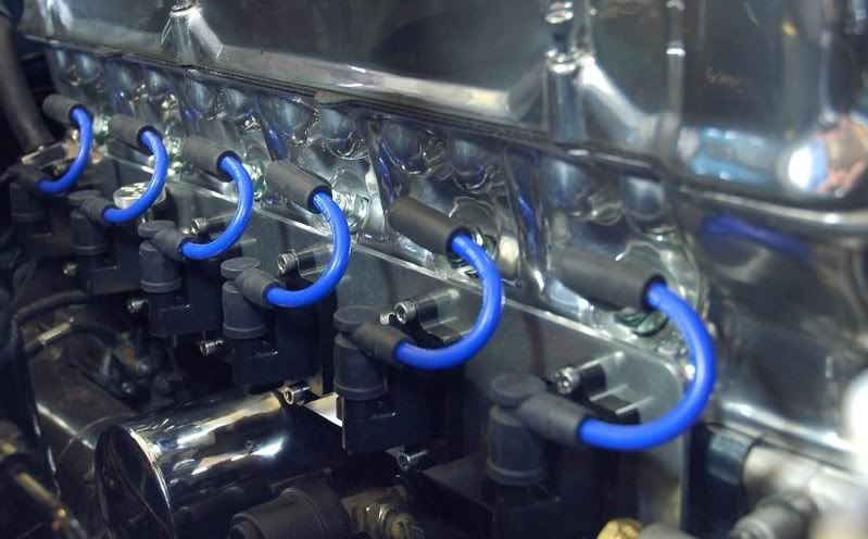
LS1 Coils...
LS1 coils (both Vette and Truck) are probably the best bang for the buck, along with the added benefit of integral ignitors for easy and direct wiring.
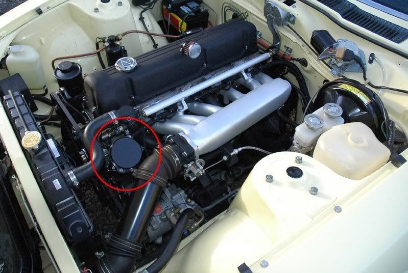
Example truck coil installation (Coil bracket and Magnecor wires availble from me)...
Coil Part# 12558693
Connector part# 12582189
Note: The connectors only come in batches of 4, as a sub-harness
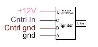
LS1 coils are 4 wire...
Pin A... can be grounded to the block, but my preference is the head (Make sure your engine grounds are in good condition).
Pin B... needs to be grounded to the same location you ground Wolf.
Pin C... to Wolfs ignition channel.
Pin D... provide a good 12 volt power source (with key 'on').
-
Primer...
Wolfs ignition outputs are very flexible, allowing you freedom to choose almost any conventional (inductive or CD) ignition system.
V500 provides up to 8 independent ignition channels. These channels are logic only, meaning they provide charge and discharge information at 8 volts, but they do not have the ability to handle the high current loads of a coil(s) directly. An ignition ignitor must be used.
In simple terms, an ignitor is a transistor... a device that allows a low current to control a high current.
Note: an ignition module, is a dwell controller that contains an ignitor. Wolf will supply dwell information, so it only needs an ignitor.
There are several ways to use Wolf’s ignition outputs... coils with integral ignitors being the easiest (Denso is a common example), an external independent ignitor (Bosch offers 2, 3, and 4 channel), and some aftermarket ignition suppliers (MSD, M&W, J&S, Crane, etc) offer them as part of their ignition package.
-
It seemed wise to start with the least understood sensor... the trigger.
Wolf is very versatile in this respect. The advantage is that you have the latitude to be very creative with the type of trigger you use. The downside is that making sense of all the choices can be a little daunting.
It would be impractical for me to list all the possible permutations, so I'll try to teach you how to 'fish' instead.
There are three primary means of triggering...
1) Crank Trigger... Allows for very precise timing. Its main shortcoming is that while it knows when a piston is at TDC, it doesn't know whether its TDC on the compression stroke or exhaust. This means you can use a multi coil ignition, but only in in a wasted spark configuration, and only batch-fired injection.
2) Cam Trigger... Can be used to run fully sequential injection and ignition. Its drawbacks are usually design complexity and the potential for timing shift as the belt/chain stretches or displays instability. However, the stock Datsun distributor (electronic ignition) contains a VR sensor and a trigger wheel with 6 teeth on it. This qualifies as a cam sensor because it is geared to the crank 2:1, just like the cam. In other words, the distributor drive 'mirrors' the cam.
3) Crank+Cam (Reference + Sync)... The accuracy of a crank trigger with the power of a cam sensor. In this scenario, the cam sensor is usually only one tooth. Its only job is to tell the ecu which event the cylinder is on and has no impact on actual timing.
Each of those three can have a variety of tooth counts, sensors, and 'types'...
Tooth counts.... Commonly 4,6,8,12,24,36,60. The simplest of these is to run a count equal to the number of cylinders for a cam sensor, or half the number of cylinders on the crank, i.e. 3 teeth for the L6.
Types...
Single pulse... A single pulse trigger is the most rudimentary. An example is a 3 toothed crank sensor, equally spaced (120 degrees), on the L6. This gives the ECU just enough information to establish RPM and when a piston is approaching, but not WHICH piston.
Dual pulse... An example of a dual pulse sensor would be to add one more tooth immediately after one of teeth of the single pulse sensor, making it a '3+1' trigger wheel. Now the ECU can determine WHICH cylinder pair is approaching TDC. I say 'pair' because, for example, cylinder one and cylinder six reach TDC at the same time. If you utilize a dual-pulse CAM sensor, there would be 6 primary teeth with one 'dual pulse tooth' (6+1). With a 6+1 Cam sensor, the ECU can tell the difference between one and six. This is the key to having fully sequential ignition and injection.
Example Dual Pulse trigger, rotating counter-clockwise. There are 6 primary teeth with a 'sync' tooth just after a primary...
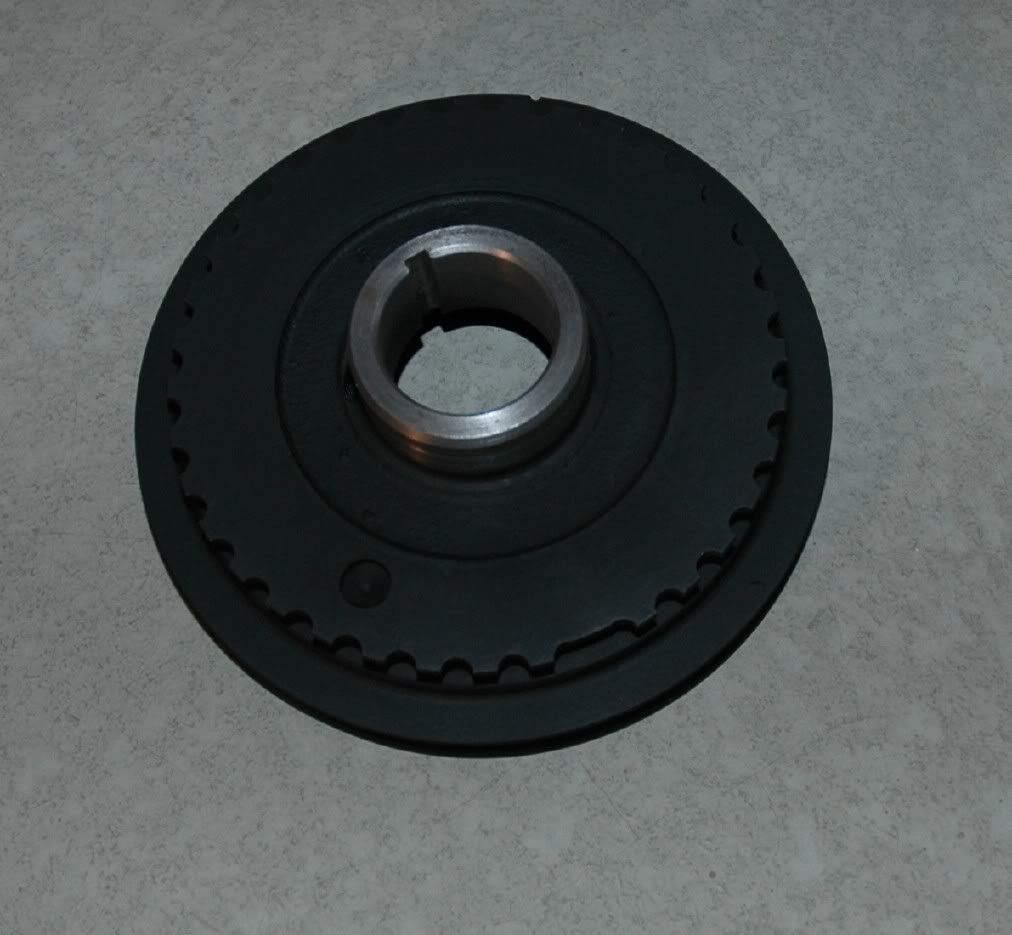
Missing Tooth... Same potential as the dual pulse trigger, but there are normally a larger number of teeth... Common counts would be 36 (making it a 36-1 wheel) and 60-2. I probably wouldn't recommend anything less than a 12-1.
Example missing tooth, 36-1 crank trigger....
Pick Up Sensors....
VR.... Variable Reluctor's are generally inexpensive and readily available. They are 'passive', meaning unpowered. They have only two wires. They can be used with very small teeth and separation between teeth, so they work well in compact applications. They produce a sine-wave, increasing in voltage with increasing RPM.
Hall Effect... Generally more expensive than VR's. They are powered sensors, with three wires and normally operate at 5 or 12 volts. They produce a square-wave (on-off). The fixed voltage makes things easy, but their biggest drawback is that they need room. Hall sensors don't discern small, closely spaced teeth very well. I would normally reserve the use of a Hall effect to a crank trigger (because diameter is usually generous) or a single tooth cam sync.
Optical... Most often the most expensive, it still remains my personal favorite. Normally produces a 12 or 5 volt square wave ('on or off'), and can be quite compact. In my experience, its nearly faultless.
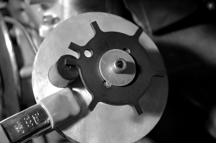
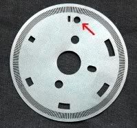
As you can see, there are pro's and con's to each.... so what's the best choice for your application? Depends on your needs, but in terms of the best L6 trigger for the least amount of effort, I prefer to use an optical trigger from a late 280ZXT. Its nearly a bolt-in. It requires only that you also use the quill shaft that drives it (its splined instead of keyed like the NA L28). It has six slots, one for each cylinder. This puts in in the 'single pulse cam sensor' category. If you use it in unmodified form, you can run batch injection and distributed ignition. If you drill a .100" hole, .060" to .080" AFTER one of the slots, it now becomes a 'dual-pulse cam sensor'. This means fully sequential injection AND ignition are available. It takes all of 30 minutes.... if you take your time. Here's a picture of the modified disc....
Note: that disk is actually from an Z32. The only difference is that all 6 slots are the same width on the 280ZXT.
The exact location and shape of the hole is not terribly critical. Its only there to provide a 'sync' so the ECU knows which slot is which cylinder. I've personally tested this sensor to over 7500rpm, without trigger errors. I know others have run them over 10,000 rpm, without error. What's wrong with it? Outside of being a little bulky, you'll probably want to modify the distributor cap to get rid of the unused HT outlets. One way is to simply cut them off and fiberglass over the top. Here's a picture of one with a billet aluminum 'cap'....
If you're wondering about backlash in the drive gears... I installed a cam and crank trigger on an L4 (same drive mechanism as an L6), attached a dual channel oscilloscope, and ran the engine, while recording the traces. Comparing the traces showed +/- one degrees 'scatter'' about 90% of the time, with a maximum of 2 degrees, occasionally. Not Formula 1 consistency, but quite good for most of us.
Note: One 'can't do' with a trigger is use tooth counts that are not evenly divisible with the cylinder count. For example, a 6 tooth wheel on a 4 cylinder... 6 divided by 4 = nonsense.... and that's how the ecu will see it. On the other hand, 12 divided by 4 would be 'logical' to the ECU. "But Ron, you said I could use a 3 tooth trigger on the crank?". I sure did. My reference is to cam timing in this case. Since the crank makes two complete revolutions for every cam revolution, a 3 tooth crank wheel is equivalent to a 6 tooth cam wheel. 6 divided by 6 = 'logical'.
By now, a few things should be evident...
1) No single pulse trigger will run multi-coil ignition or sequential injection. Batch injection and distributor based ignition is the so called limit.
2) A crank mounted dual pulse or missing tooth trigger, opens the doors to wasted spark multi-coil ignition but still must retain batch fired injectors.
3) A cam mounted (or distributor) dual-pulse (or missing tooth), provides a means for full sequential injection and ignition.
4) A Reference+Sync. trigger will also deliver fully sequential ignition/injection, with the accuracy of a crank trigger.
-
It wasn't directed at you. It had more to do with the morbid nature of the video. I don't need to see it more than once. In fact, I could have done without ever seeing it. Peace Bro.
-
Where the hell do you find these?!?!?!?!
You've been PM'd
-
might want to tell people to .right click and .save as
No offense intended but, no way in hell you'll get me to put THAT on my HD.
-
Do you think I could make this system produce ~200 - 225 HP without significant risk of detonation?
Offhand... NA motors, on stock cams, can make over 200hp. Unless your turbo resembles a cork, I don't see why not.
-
Welcome Ross,
I see some 'red flags'... but I don't see any questions. What (specifically) are you are asking?
-
I'd stick with an idle timing closer to around 16-18, as that's a pretty high idle. Going a little richer than 14.7 at low RPMs generally helps the engine stay stable. Remember 14.7 is the theoretical ideal for perfect combustion/low emissions. That's again theoretical, different engines run better at different AFRs.
My original statement was centered around *only* passing emissions at idle. My suggestion would 'kill' a perfectly good running Z
As for idling up and down, that's generally a vac leak.
On a known good tune, that would be my first guess. On a standalone system, with only a 100 rpm hunt... statistically, its a tune problem.
-
Any idea about the exhaust side?
No Way Jose.
-
:trippen:


Resistors vs. PWM for injectors?
in MegaSquirt
Posted
The current limit function is to protect and properly control low Z injectors... not the drivers.