

RTz
-
Posts
2943 -
Joined
-
Last visited
-
Days Won
23
Content Type
Profiles
Forums
Blogs
Events
Gallery
Downloads
Store
Posts posted by RTz
-
-
I'm with Patzky all the way.
I have NEVER had an instructor take the controls from me, with three exceptions...
1) Once, while landing in a 40 knot wind, ground speed zero, I got the plane on the ground nicely (and stopped)... but it wasn't done flying... a gust rolled us up on our side to the point of the outboard wing coming within 12 inches of the runway. Instructor saved the plane. Barely. At that time I was too inexperienced for that situation. Probably still am.
2) If I asked him to demonstrate something I didn't understand.
3) If he wanted to demonstrate something... uh... 'outside the normal scope of training'
 We had LOTS of fun.
All of my instructors have allowed me to make mistakes. That's how you learn. Take for example the student that enleans at altitude, later descends, forgetting to enrich, and subsequently kills the engine. You can bet your socks that student will NEVER make that mistake again. That particular story isn't mine, but I have a few like it. Controlled environment is KEY. Providing that environment is the instructors job.
If it were me, I'd introduce that instructor to the two step program...
First, respectfully state you thoughts. He may have a surprisingly good answer. He may even be receptive and adjust his style.
Second, If you don't strike an accord, pay the Chief Flight Instructor a visit and get yourself an instructor that knows how to instruct.
-
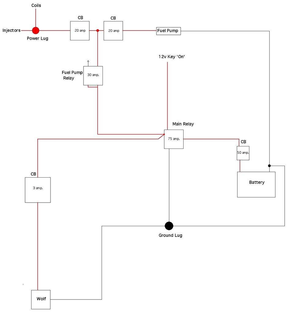
The Foundation... Power and Ground Distribution.
A simple power and ground distribution circuit....
A Few Notes:
1). I prefer to use circuit breakers (CB) in lieu of fuses. This reduces of the chances of not being able to reactivate a circuit because I didn’t have a proper fuse along. And frankly... I trust a good ‘ole’ aircraft CB over some of the crappy fuse boxes I’ve seen. CB’s are convenient, reliable, and affordable... they also halt the tendency to ‘fix’ a problem with a bigger fuse
2). Power runs from the battery to a main CB (located as close to the battery as practical), then on to a main relay. The main relay is switched on by the ignition switch. The relay takes the low current from the ignition switch and closes internal contacts, allowing a high current to pass through the relay. From there, the power is split two way’s... one to a 3amp CB for the ECU, the other to a 30amp fuel pump relay. The Fuel pump relay, activated by the ECU, distributes power to the fuel pump, injectors, and ignition coil(s) via two more CB’s.
3). If you think this through, you’ll realize that the injectors and coil will not receive any power unless the ECU activates the fuel pump. This is true. Typically, an ECU will request the fuel pump under two conditions... for a couple seconds upon initially turning the key ‘on’ (to prime the fuel system), and anytime the ECU detects the engine is turning. Normally, there is no need to have the fuel pump on outside of these two conditions... and normally there is no need to power injectors or coil outside those conditions. This method has some minor drawbacks... but it keeps things simple.
4). You’ll notice both a ground lug and a power lug. In my experience, there is less chance of EMF of RFI, when every ground of the EFI system is grounded to one chassis ground, and that location is grounded directly to the battery. The exception is that I prefer to ground the ignition coil directly to the cylinder head (if it has a dedicated ground). That provides a direct ground path for the spark plugs. The power lug is simply for convenience. It allows easy access for future use (for EFI purposes only!).
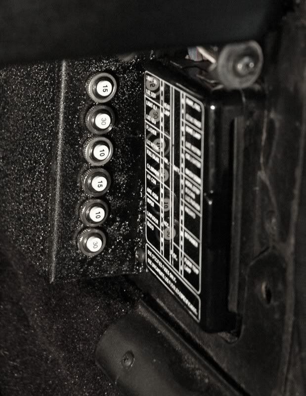
CB's installed in passenger footwell....
.
.
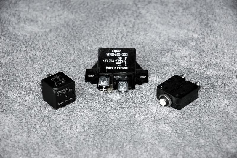
From left to right, 30 amp. relay, 75 amp. relay, and an aircraft CB...
-
Wiring Primer.
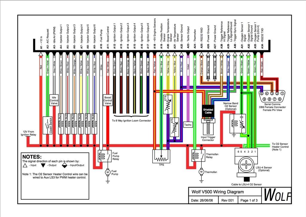
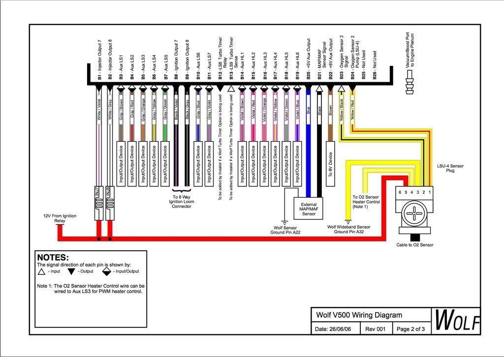
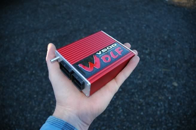
V500 has two connectors, A & B.
Connector A diagrammatical...
Connector B diagrammatical...
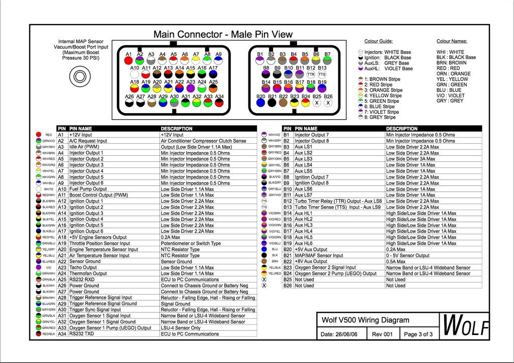
Pin-Outs, A & B...
Preface: Installing an EMS is a lot like oil painting... What is ‘correct’ is defined by the artist. In other words, there are an infinite number of way’s to install an EMS, all different, that will work ‘satisfactorily’. Everyone has their own style... and that’s part of what makes it fun. Don’t become obsessed with doing it my way... my way is only one way. Further, every installation I’ve done has been unique... no two are alike. I make an effort to cater to the customer and his/her intended usage.
EMS function can be divided into two main categories... Input and Output.
Example Outputs:
Injectors
Coils
Fan
Fuel pump
Auxiliaries
Shift Light
Audible and visual warning indicators
etc., etc.
Example Inputs:
WT
IAT
TPS
MAP
O2 Sensor
Trigger
Auxiliaries
etc., etc.
Outputs...
Most EMS’s, including OEM, work in a similar fashion with respect to outputs. That is to say that power is provided to various solenoids, actuators, etc... and the ECU grounds them (completing the circuit) to activate.
Example.... an injector has two ‘pins’. One pin is wired to 12 volts (with the key ‘on’) and the other pin is wired to the ECU. When the ECU wants to activate the injector, it grounds the pin (another way to say this is ‘pull low’). Another example... The fuel pump is run by a relay. The relay receives 12 volts with the key 'on'. The ECU pulls the relay ‘low’ to energize the fuel pump.
Exceptions always exist, but that is the most common method of controlling an output.
For a teaser, several of Wolf’s auxiliary outputs can pull both low (ground) and high (12 volts). This can lead to some very creative control... a topic for another day.
Inputs...
Inputs are more diverse. They range from millivolts to over 40 volts (VR sensors can produce considerable voltages).
Common sensors (TPS, MAP, WT, AT, etc.) are 5 volt. The ECU will supply a regulated 5 volts to these types of sensors. The sensor, in doing its job of ‘measuring’, modifies the voltage and ‘returns it’ to the ECU. The ECU will be calibrated (through the software) to know that a return of 1.25 volts is ‘equal to such-and-such’.
Triggers produce a wide range of voltages, from very low to very high (with respect to a nominal 12 volt system). Hall effect and Optical sensors are square-wave and typically 5 or 12 volt, whereas VR’s are sinusoidal (sine-wave) and voltages are virtually ‘anything goes’.
-
Idle at 14.7:1 and back timing down... try about 10 degrees.
-
Polished.
Never been a fan of black wheels. They are typically featureless as soon as you take a few steps back... the black 'wheel' looks the same as the black 'holes'.
-
Plenum style manifolds have the potential to be...
Less expensive.
Lighter.
Use the plenum as a tuned spring (resonance chamber).
Easier to get 'clean' air.
ITB's have the potential to be...
More responsive.
Easier to 'get right' (less variables).
Sound GREAT
Ron Tyler also built a very nice one, but the end result on the dyno wasn't very spectacular. I don't know if that was the plenum's fault or the rest of the engine or what.Jon may very well be right about my plenum. I suspect part of it is the combination... aggressive manifold and head, mated to a low comp. engine with a very mild cam and mild exhaust. The peak number isn't there. In defense, I will say its one of the sweetest running engines to come out of the shop. The dyno isn't telling the whole story... and never does.
-
My three year old would go nuts driving one of those!!!
Agreed... so would I
-
No Ford Flathead???
.
.
Happy?
-
This is the first of several articles aimed at aiding the installation of a Wolf3D EMS. Its not intended to be ‘all encompassing’. Rather, a simple guide to get things jump-started. I will add/update as time permits.
What are the Minimum Sensor Requirements?
For a fuel only system, you will need a minimum of...
RPM sensor (trigger)
Load sensor
Water temp. sensor (WT)
With those three sensors, you can successfully run any typical gas engine. Later I’ll cover adding supplemental sensors to achieve a better overall package.
Summarizing the Three Sensors...
WT (Water Temp.)... The primary function of this sensor is to aid in cold running. When the engine is ‘cold started’, a richer than normal mixture is needed for best operation. As the engine warms up, fuel can (and should be) reduced. Its a bit like an electronic version of the choke.
RPM... A common name for this sensor is ‘trigger’. Trigger’s can be very simple, or very complex. This is an entire topic on its own and outside this articles scope (I’ll cover some basic triggers in another installment). A fuel only system is simple enough to require only a very rudimentary trigger. For example, the stock Datsun electronic ignition distributor contains a VR sensor (Variable Reluctor), with six teeth. This trigger can only tell the ECU when a cylinder is approaching, but not which cylinder. This type of trigger would only allow batch-fired injection (and distributor based ignition).
Load... There are a number of ways to determine load. The three most common are...
MAP
AlphaN
MAF
Briefly....
MAP (Manifold Absolute Pressure)... is most commonly used and is sometimes referred to as ‘speed density’. It measures the pressure in the manifold to determine load... high pressure=high load. Its advantages are simplicity and accuracy under most conditions, with a natural tendency toward altitude and barometric pressure compensation. Its biggest drawback is its inability to compensate for modifications or engine wear. In summary, anything that changes the airflow of an engine under any given condition without a corresponding change in manifold pressure causes an inaccuracy. Note: a 3-bar MAP sensor is built into Wolf's ECU.
AlphaN... uses a throttle position sensor (TPS) to determine load. Like MAP, it has no ability to compensate for modifications or engine wear. Additionally, there is no barometric pressure compensation. You may want to add a barometric pressure sensor to compensate for altitude and barometric changes. Another pitfall is that pure AlphaN will not work with a turbocharged engine. A TPS is unable to distinguish the difference between 2 psi or 20. AlphaN’s advantage is with aggressively cammed NA engines (making around 10” vac. or less). In short, most hot cammed engines vacuum signal is unstable at idle. With a MAP based system, this causes erratic cell movement at low rpm/light load (i.e. idle), within the fuel map (see footnote for a sample fuel map).
MAF (Mass Air Flow)... uses a thin piece of heated wire. As air moves across the wire, the wire cools. This in turn, lowers the resistance of the wire. The ECU uses the resistance to calculate the mass of the air drawn into the engine. MAF is one of the most accurate methods currently available. Its primary drawbacks are cost and installation complexity.
Footnotes:
Highly Recommended Sensors... I mentioned earlier you can add sensors to enhance the overall performance. The two that should be highest on your list should be a TPS and IAT.
A TPS, optional on MAP/MAF based systems, is capable of doing a number of things, but its most valuable function is acceleration enrichment. The MAP/MAF sensor can serve the same purpose, but its a little slower responding, so achieving crisp throttle response is a bit more challenging. There are a number of other TPS benefits such as fuel cut, flood clear, data acquisition, and auxiliary activation... we’ll get to those later.
The IAT (Intake Air Temp.)... As the temperature of air increases, its density decreases. We want to match the volume of fuel to the mass of air, not its volume. The IAT is part of the means to compensate for air density changes.
Ignition Timing Control... For a system that includes ignition timing control, the above mentioned list meets the minimum requirements for a distributor based system. If you want to run a multi-coil ignition, a more advanced trigger will be necessary.
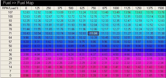
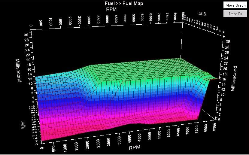
Fuel Map... The fuel map is a 3 dimensional graph expressed as numbers (as is the timing map). Across the top, you have RPM (in 125 rpm increments). On the left are load bands (in approx. 7% increments). The numbers in the cell’s are injector pulse-widths (‘on time’ in milliseconds)....
Same map, in graphical form....
-
I wonder why there isnt big forums and stuff with these people posting.
I suspect its because they're too busy working
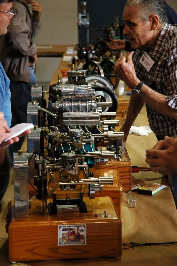
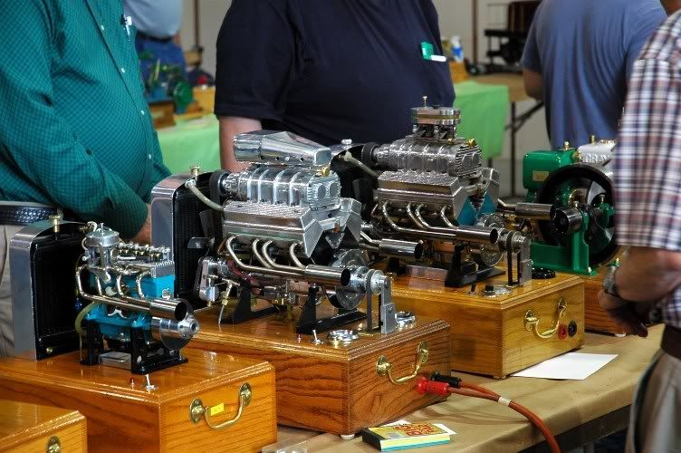
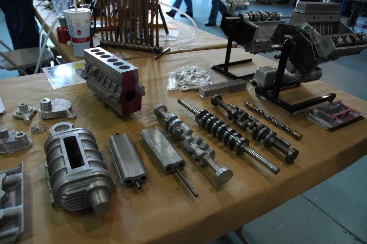
As Braap mentioned we 'crashed' the GEARS show. I had obligated myself to a head gasket replacement so wasn't able to spend much time there. I think we were there total 1 1/4 hr... could've spent ALL day there.
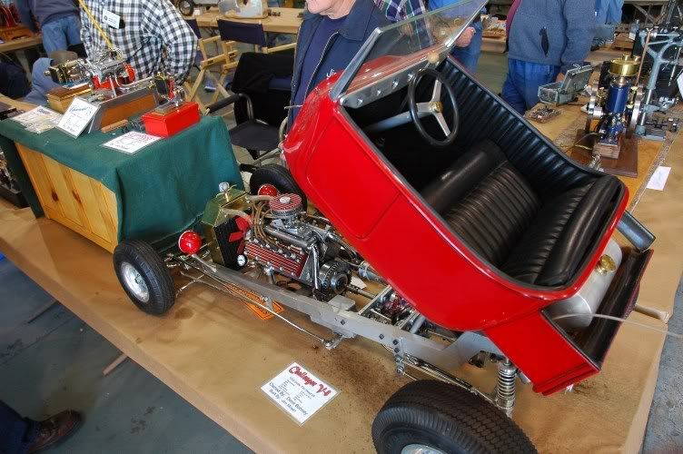
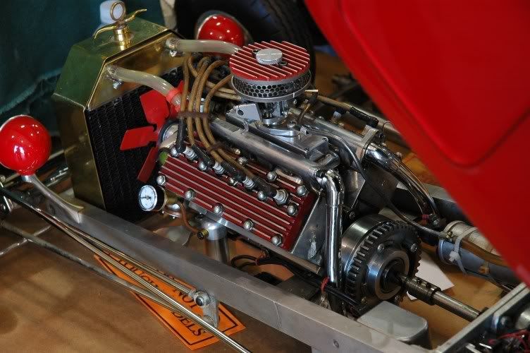
Anyhow, a couple more pictures for the archives....
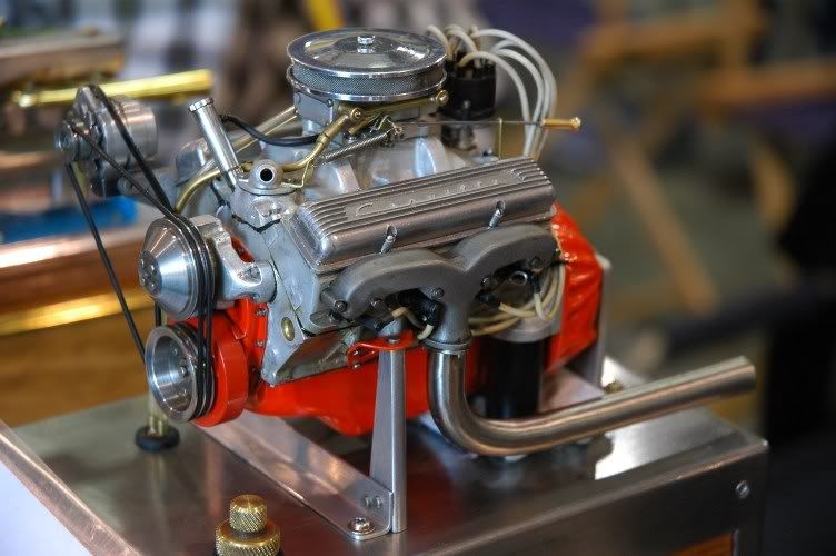
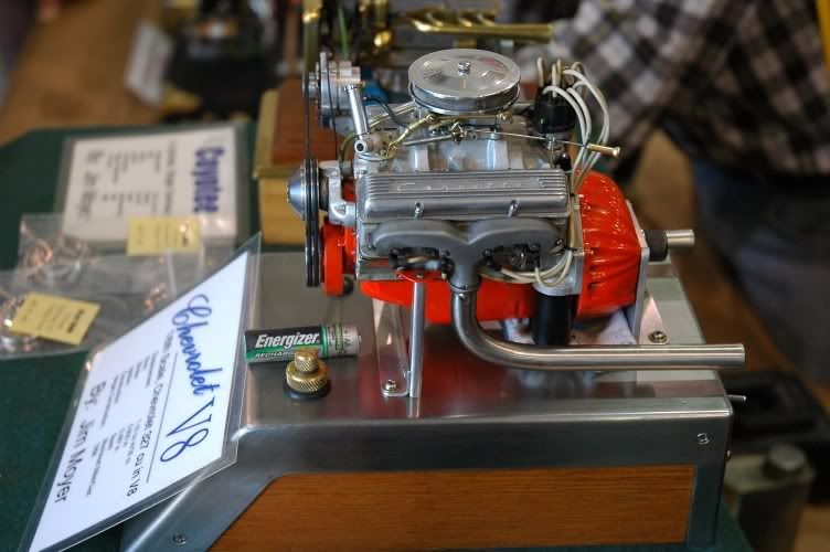
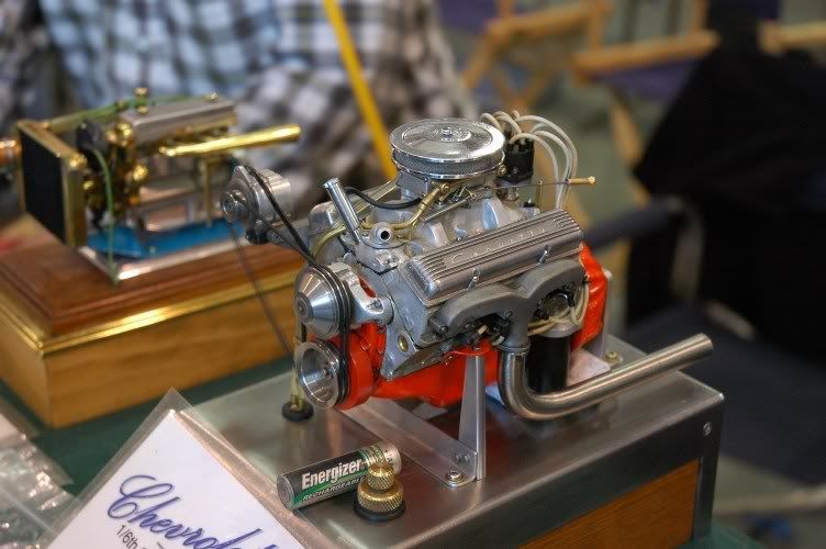
Jim Moyer's stunning 1/16th scale Chev. V8....
Profile adjacent a AA battery...
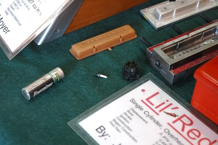
Spark plug and valve cover adjacent a AA battery...
Running (notice the blurred alternator belt)...
IC heaven...
Misc...
-
Thanks Ron. I picked up 240hoke SDS for a great price plus it's setup for the L series already. Your 2 months to late...
No worries. Just an effort to clarify for subsequent readers.
-
Any suggestions on an EMS for my setup? In my other thread in the non-tech forum some suggested Wolf but that is $2K.
When visiting Wolf's website, you must click the American flag to see US dollars. The current exchange rate puts the system substantially under $2K, and I also offer a discount to donating members of HybridZ.
-
Nice work Bryan! Kudos.
-
i guess you are the man to talk to about my EMS dillemma
I'm not much of a piggyback fan. That's not intended to be derogatory, they just don't normally fit my needs.
I think they're great if you are happy overall with the current tune, but just want to massage a couple area's. They're generally affordable and easy to install/use.
Standalones are an entirely different level of control. I don't have time for a novel tonite so start with this... it'll keep you busy for a bit... http://forums.hybridz.org/showthread.php?t=119404&highlight=ECU
Hey Ron correct me if I'm wrong, but this might help in his searchPeak and hold = Low impedance
Saturated = High impedance
Correct. Any EMS designed to drive P&H will also drive saturated, but not the contrary.
-
In a nutshell, P&H's can generally be opened quicker (by overdriving them). The drawback is usually their increased cost.
-
-
Very Cool.
-
doesn't the wolf have a 2 bar internal map sensor?
3 Bar... one bar below atmospheric and two above. For a maximum of 30 psi. Note: You may use any available external MAP sensor.
Where did you get your base map?
I'll provide you with one.
I have been looking for a wolf tuning forum to no avail.
I approached Wolf on this topic several weeks ago. It may happen, but it wont be tomorrow. I'm expecting Superdan to create a Wolf specific forum on HZ, which will be a start. Meantime, its you and me, Baby
-
So is there the option of running AFR and VE, or is it just injector time.
'Pulse width tuning' sounds a little complicated initially, but I have yet to find someone whom has tried that style of tuning and not appreciate it. Its easier than it sounds, makes complete logical sense, and you know where you stand, at all times, without question. Its the only way I'm interested in tuning these day's
'AFR tuning' is pure marketing, in my opinion. With currently technology, its not capable of working sufficiently for anything other than a course tune. Root causes are the response rate of the O2, the distance from the O2 from the chamber, and the processor's ability to sample/adjust/sample/adjust. By the time its calculated and applied the correction, you're no longer where you were.
Now if I can just figure out how to get the Wolf3D out of the cardboard box it came in, I'll be on my way...(j/k)
I'll loan you a sawzall?
-
Rotor speed is 1/3 eccentric shaft speed.
-
[/i]would it make sense to just remake an entire harness rather than use the plugin that Wolf has for the RB26? I mean using their standard plug in harness and rewiring most of the connectors and whatnot?
There are pro's and con's to both choices.
Briefly...
I'm sure Bo will concur, a custom harness (universal-fit) is time consuming. If you want a tidy, reliable system, for years to come, be prepared... it takes time. I've never spent less than 100 hours installing any EMS. However, as you mentioned, your understanding of the system will be be incomparable... I assure you.
A 'direct-fit', has the potential to have your car running well in a handful of hours. Outside the lack of personal accomplishment (ask Bo about this
) and system understanding, the biggest drawback I see is age. That is to say, the under hood temps of a Nisssan DET(T) are typically high and this takes a toll on the OE harness. They are getting old enough now that it needs to be considered.There are innumerable small items as well, such as a small monetary hit with a direct-fit (around $100), along with a potentially better fit to your Z with a universal-fit, etc, etc.
-
Bo,
Do you want this stay on topic, or let it roam? Your call.
-
Someone forgot to mention how similar to the Wolf V500 Ron Tyler's new logo looks.
-
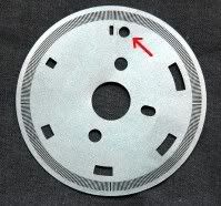
So what does the optical wheel look like on the distributor, 6 slits and a HOLE?
Correct...
The hole has no timing influence and its position is non-critical. It simply needs to fall within a 'window'. When Wolf sees the 'dual-pulse', it knows that slit is cyl. one. Engine position is calculated from the leading edges of the slits.


For the Pilots....Nervous Instructor?
in Non Tech Board
Posted
I would agree, at times, that action is appropriate.
Globerunner seems to be talking about something entirely different... of course, there are always two sides to every story. Thats why he needs to civilly present himself to his instructor... Globe just may glean a new perspective. Further, if they can't work out issues on the ground, they don't belong in a plane together.