mtnickel
-
Posts
335 -
Joined
-
Last visited
-
Days Won
5
Content Type
Profiles
Forums
Blogs
Events
Gallery
Downloads
Store
Everything posted by mtnickel
-
Question on Fabricating Transmission mount / Driveline angles
mtnickel replied to mtnickel's topic in Nissan RB Forum
My angle finder was a great little digital unit about 1.5" long with strong magnets on it. Worked great directly on the output shaft and the diff flange. I was only using the reference line of the frame rails to show that the diff was pointing up a fair bit. The main problem with the R200 in the stock mount is that with the roughly 4.5* upward angle to match that you would need to drop the trans tail a fair bit (to get the 4.5* on the trans). This puts the centerline offset well over 6*. With my new RT diff mount I'm now at about 3* on the diff. I shimmed and jacked my engine to get it to the same 3* and it's sitting pretty in the tunnel. I have about a 1.7" centerline offset still (which equates to about 4.5*) but I can live with that. There really isn't much way around it. The oil pan is about as low as I can go on the cross-member, so the only way I can lower the trans angle is to raise the rear of the trans. I'm already quite close to the stock fuel lines (the rb trans breather pipe just barely rubs them). The only thing else that will work (and is possible) is to drop the diff about 1/2" both front and back. I could put washers under the moustache bar and under the trans mount, but at this point it's not worth it. Now that the engine and trans are sitting pretty I just need to make the mounts. Simply put a 1/4" plate on the engine and a 1/4" plate on a mount on the stock mounting location. Now just some 1x2 Tubing to connect the 2. Going to reuse the stock transmission mount ears as well. Pics to come! Mark -
Question on Fabricating Transmission mount / Driveline angles
mtnickel replied to mtnickel's topic in Nissan RB Forum
You're right in that the centerline doesn't matter nearly as much as having EQUAL diff and trans angles. If the angles are unequal, the joints bind basically and cause vibrations. The centerline offset dictates the woroking angle of the u-joint and it's generally accepted that you want the working angle under 3 degrees and at least .5 degrees (so that the bearing lubricates itself). From reading the spicer tech docs the numbers I listed above are more absolute maximums (but not sure if that's instantaneous or during it's working life...most likely during it's life). I just went ahead and got the Poly GM mount for my RT diff mount and will get angles under control. I also picked up a digital angle finder which works pretty slick. With the Frame rails as a level reference, the stock diff mount and moustache bar for an r200 (3.54) in an early 260z result in about a 4.5* upward angle. I'll see where it's at with the Poly mount installed. heres a decent well witten article... http://www.hurst-drivelines.com/files/Universal_Joint_Alignment_Proc_111606.pdf this time they show 3.5 but make no mention of how much higher you can go, but they do state that you can increase that angle and sacrifice longevity. -
Question on Fabricating Transmission mount / Driveline angles
mtnickel replied to mtnickel's topic in Nissan RB Forum
Wizard, did you mention in the other thread that the offset angle could be as much as 7 degrees? I was under the assumption 3* was max. But now looking at a chart, it looks like I could get away with higher. SHAFT RPM OPERATING ANGLE 5000 3.25° 4500 3.67° 4000 4.25° 3500 5.00° 3000 5.83° 2500 7.00° 2000 8.67° 1500 11.5° This is for operating load and lifetime of 3000hrs. for a doubling of angle or RPM the lifetime will be cut in half. Doing a little math, with a 3.90 diff at 100km/hr (about 63mph), the driveshaft would be turning around 3200rpm. Looks like maybe i can get away with the 5-5.5 degrees I may have. I will do my best to shim up the moustache bar a touch to help things out though. Pics and mounts should be done mid to late next week. -
Question on Fabricating Transmission mount / Driveline angles
mtnickel replied to mtnickel's topic in Nissan RB Forum
That would work i'm sure. Perhaps overkill though. Remember that the trans mount only really needs to support the weight of the transmission and roughly 25% of the engines weight. Anything as strong as the stock mount would work. Even look at the geometry of the mckinney mount...it extends backwards almost 5-6" from the stock mount. The leverages and torques involved would be even less strong than stock, yet you dont' hear stories of the RB doing any damage to the stock mount locations. Anyways, more on my progress. I got the engine fairly well positioned, however I believe how the R200 is mounted it is not going to provide very good driveline geometry. It points up such that its pointing at a spot below the shifter tunnel by about 3". Follow me on the math here: The U-joint's are separated by about 21.75". (you would measure from these pivots for driveline angles, not the yoke or diff flange). For 3 degrees of u-joint angle you get tan(3) = x/21.75. Solve for x = 1.14". So when the diff centerline is pointed at the transmission output shaft, it should be no more than 1.14" away from center. The closest I could get is about 2-2.5" which results in a driveline angle of 4.25-5.5*. The centerline is just too high which puts clearance from trans to tunnel at an 1/8" and physical contact with fuel lines on the reverse/neutral switches. Looks like main option needs to be shimming the diff to a lower angle. I've read that the rear covers can vary a fair bit in the stud position and that some result in a much worse driveline angle (as much as 10*). Since I'm close I wouldn't think that's the case. So looks like those who do it right maybe use a front RT mount or just shim the rear moustache bar. I could probably pull out the top washer as well as grind down the metal of the bar insert maybe another 1/8". Probably gain 1/4" total. That might move the centerline down maybe 1/2-3/4". I really think the better solution may just be the RT mount. Any thoughts? -
Question on Fabricating Transmission mount / Driveline angles
mtnickel replied to mtnickel's topic in Nissan RB Forum
thanks for the quick reply. The more I think about it the less it makes sense. You are bang on about the torsional loads. As the mount is 10" wide, rotational changes in the engine may result in large amounts of movement at the ends and stress the tunnel. I should be able to make something work. I am just double plating the tunnel over a 6" x 8" area with thick 2mm plate. I will post some pictures when it's all done. Thanks. -
Hi guys, Just a quick question. I'm fabricating a transmission mount for an RB25 into an early 260z. I have the ear-style mount system. I cut off stock ears to make way but am also going to re-use the brackets and stock mount. the Question: Does anyone see why there would be a need to have a transmission mount when using the stock ear mount style? I know the stock engine had a mount, but my rational is that the rubber isolators that go into the ears should provide a fair bit of movement. I would simply cut the round ends off the stock mount and fab up a piece of flat stock to bolt to the transmission and be welded to each end. It would really allow me to keep a large amount of exhaust clearance. Thoughts much appreciated. Second Question: What rear diff mount are people using with the RB? I've read also that some of the rear diff covers on the R200 have the studs positioned differently resulting in different driveline angles from the rear. I've measured mine about 5.4* up. Of course this number is all relative, but to put it into perspective, it points at a spot 3" below the shifter opening.
-
Wow that is Tidy! Does this replace all the original wiring as well? Mounts on the firewall or passenger kick area? I need to do mine soon but was going to relegate a large portion of relays and such to the engine bay beside the battery. I picked up one of these from the wrecker and am going to repurpose it a bit:
-
Update: This is just a small small portion of the crap that falls on my face all night long... Top of battery tray was rusted/pitted so I couldn't see the spot welds that well. Just ground off the back side and was pretty easy. Probably better access anyways. Before: Out (nice little pine needle collector). **EDIT** Figured out how to get the fusible link through. 1) take off the links. 2) IT BARELY fits...Jammed by thumb pretty bad on the edge doing so, but alas, wiring harness is out. Now just a few more things to remove before I can prep the engine bay. Trying to get down to the bare metal. Looks like the previous owner at least converted this rust (black areas seen). It doesn't sand well either actually. Going to hit the whole area with some por-15 pretty soon. Also cut out some more rot. 7 Is this the best forum for even the body-work stuff? I have it on Zcar too, but not sure which are the best forums to post this kind of stuff. Just looking for any comments or tips along the way. Seriously I'm very new at this stuff.
-
Here are other parts accumulated that will go on: - RB26 injectors and fuel rail, Honda 95-2000 V6 injector resistor pack and pigtail. - Kinugawa TD05H - 18G turbo with billet wheel and T3 style exhaust housing. Think this cost around $800. At the time they didn't have the RB specific housings, but It shouldn't affect me too much. My only concern with the turbo is boost creep. I kept it to a td05 because I wanted the ultimate in response and would be just fine with low 300whp levels. - Luk 06-902 clutch. I believe this is listed as a heavy duty D21 clutch. Rumor has it that it has a stronger pressure plate than the z32 NA clutch and should hold my goals. Will see. - GTR intercooler (will have end tanks modified to come straight through rad support) - AE86 aluminum rad. Fit's perfectly and is same side in/out. picked up a couple toyota cresida (I think) mounts that match up perfectly. only issue is the inlet hose diameter is too small. will likely slide over the proper diameter and have it welded up by AL welder. - 16x7 konig rewinds in silver (love these for size and classic look and price). - Nistune Z32-RB converted ECU - Shocks and springs are undetermined right now - Full Raammat application to interior (like dynomat) - Custom mounts made by moi. (using Jeep style universal engine mount isolators and will mock up the mounts when I align the engine) That's all I can think of for now. Will keep you guys updated.
-
Battery box after some screwdriver persuasion: Where firewall meets battery box in wheel well: Upper wheel well...uh oh Looks like that fender has to come off: Underside of Cowl...that doesn't look promising: Another: Lift latch...(Anyone have any idea what to do with this!? The top side looks perfect) Fender now off: I hate to see what's under that poorly adhering underbody that the previous restorer Sprayed EVERYWHERE. But here it is anyways: Anyways, that's all the investigation I've done to date. I really am not quite sure the best way to fix this last area. If anyone has tips I'm all ears. It's just it's like a sealed box and i'm not sure whats to be done as far as drainage and protecting the inside, etc. Also, what do I do in the rockers? they were repaired, but who knows how well. I'm thinking maybe just eastwood internal frame rail protection. Heres some of the RB prep being done: If you get an RB25, prepare to extract some Exhaust studs. These are notorious for breaking. See those little stubs on the valve cover. I think I had 5 I had to remove. went on to preping block with some black block paint: Cleaned and now painted: Add on a greddy style intake manifold and some red wrinkle paint and here I am: Also did the timing belt and oil pan, but don't have those pics handy. I did however put up a "redneck style oil pan" thread up a few weeks back. This is all for now guys. Hope to have more in the coming weeks. And please if you have any rust protection tips and repair tips I could really use em.
-
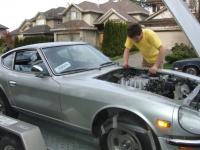
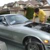
Ok, so maybe it's not a "never ending project" but I figure it will last quite a while! Really depends on how perfect I want to make it. Well I'm glad to be starting my first vintage car project! I have reasonable mechanical skills, but these datsuns and body work is pretty new to me, but I'm doing the best I can. Anyways, here it is as I picked it up some 3 years ago! I bought it as a non-running project that "has a 260z but just needs a driveshaft and a 'few' pieces". Price $3000 I was a little over-eager and didn't do too much due diligence. The body did however look very clean I thought. Interior painted, etc. Seemed like the previous restoration some time ago was at least a decent one. It had an rb25 more or less just sitting on 2x4 blocks and basically was no where near ready to be put in. Additionally the owner had cut the engine mount towers off a few inches which makes pre-bought mounts impossible. Anyways, it was a daunting project and due to lack of space it sat for 3 years. Fast forward to this year and I'm in a townhouse with at least a small garage and have taken to getting her up and running. Step 1) Frame Prep. I knew but looking that the stock frame rails were pretty dented up and would like need some beefing up. I picked up the bad dog rails. Here are a few pics of where some of my progress. A little chizzling led me to this.... Passenger side didn't seem too bad... So I ventured off starting the Driverside Cut out the damage: Dented old rail Also, both sides like to rust out at the very back of the frame rails: Time to template: Tack it in: Prep the bad-dog rails with zinc spray on the backside: Rail in: A couple more pieces made and tacked in (one is out of place...ran out of welding gas). Front of bad dog rail: I still have to weld the rest of that side up, but since i was out of gas I went on to preping some of the passenger side: Stripped the bottom with a needle scaler and found the previous owners patch...this was my first sign that I could be in for some surprises if they weren't done right...this one happened to be ok. A few more pieces cut out: Those patches will be made soon. Here's some more investigative work. Driverside dogleg looked pretty solid. Looking inside the rail I could see there was some old rust in there but new metal must've been put in. There was piles of junk so I ground down the pinch seems to see if I could pry it open. Looks like the previous owner brazed it on to avoid any burn throughs. Passenger side feels and sounds solid, but that bottom left corner with the rust through the paint is certainly distressing. not sure i want to dive into this: Here's fender well side of it...looks Ok? More investigative work: Driver side front rail:
-
I've read theses air straighteners can really clean up the maf signal.... http://www.ebay.com/itm/3-5-88-9mm-OD-x-5-Air-Straightener-Screen-25-6-35mm-open-cell-/251337605931?pt=Motors_Car_Truck_Parts_Accessories&hash=item3a84e3832b&vxp=mtr I don't know that this is the exact one to get, but if you read up a bit, it organizes the air and stabalizes the maf signal. As an alternative to a standalone, if you are ok at soldering Nistune is a pretty good option. The RB25 Ecu isn't readily compatible, but there is a writeup on converting a Z32 ECU to work (cutting a few board traces, soldering a few resistors, etc). After that you have the option of buying the full nistune board, burning chips a few times to get a decent tune started, or like I am doing is to get an ostrich eprom emulator. Picked up the emulator for about $150, Z32 ecu for $40 (you can find them cheap if you look hard enough), $200 for the nistune software, and $40 for a consult cable adapter to USB. About $400 and a little work, but certainly cheaper than a $1000+ standalone.
-
Redneck style RB rear sump/pan DIY tutorial.
mtnickel replied to mtnickel's topic in Nissan RB Forum
On another note. Since I was lazy/careless and had the possibility of weld particles dropping into my engine as I said earlier, I rotated it upright and blasted the heck out of all the crevaces with an engine cleaning gun. Valve covers off and everything inspected. After that there was a chance the oil had been washed out of journals, so I primed the engine as follows: 1) Pull spark plugs (compression would be bad for bearings and maybe damage stuff) 2) remove pan and sump 3) Flip engine upside down 4) put funnel in sump hole 5) Crank by hand till oil pump, filter, cooler, and system is primed. Should see oil start to ooze from main/crank/cam/and hydrolic lifter spaces.
-
Redneck style RB rear sump/pan DIY tutorial.
mtnickel replied to mtnickel's topic in Nissan RB Forum
note that you will have to either modify or not use the support brackets that support the bottom of the transmission. The passenger side one will likely need very little modification, but the other side will likely need to be slimmed down quite a bit and then perhaps reinforced. -
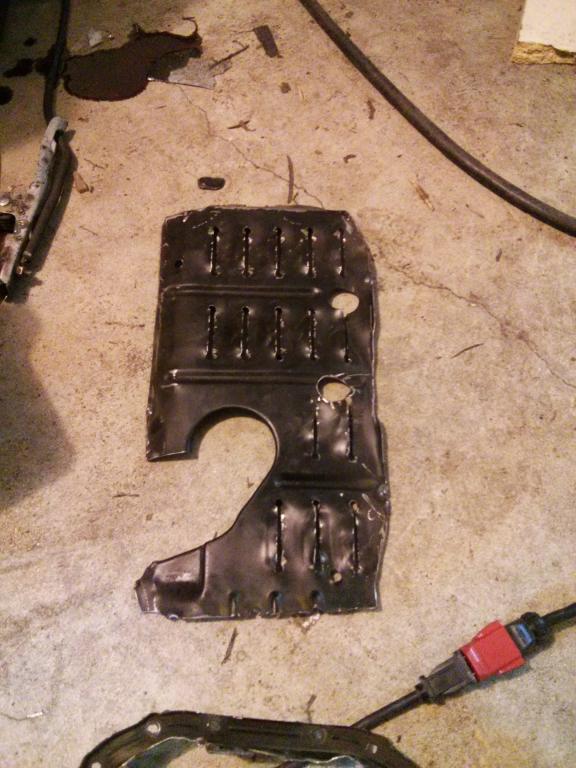
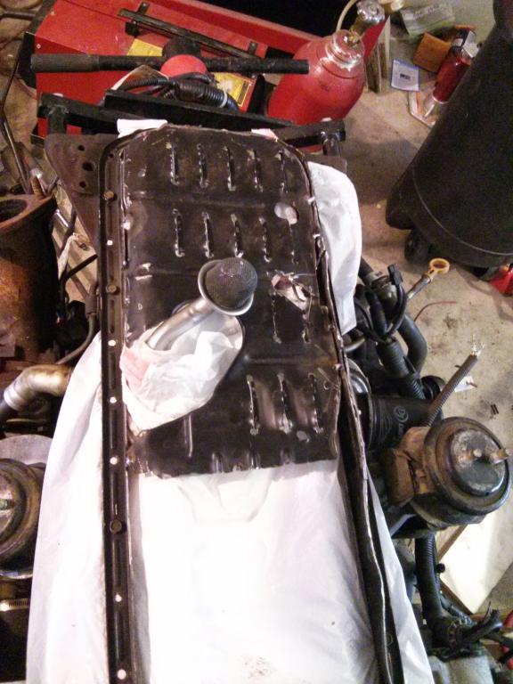
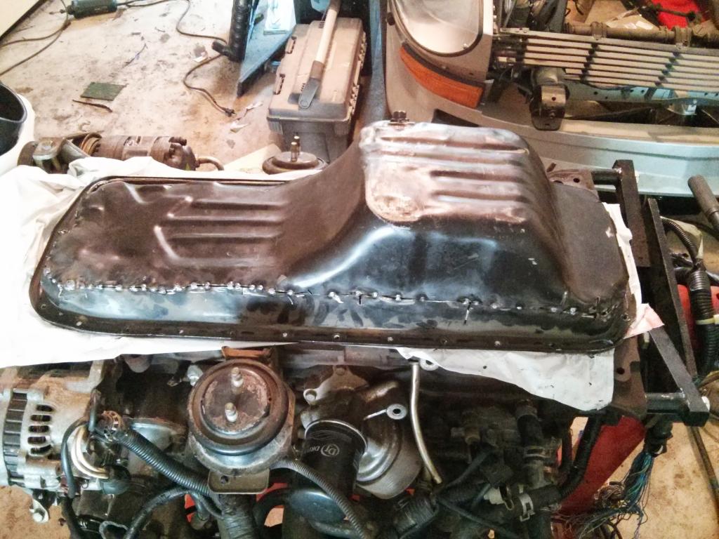
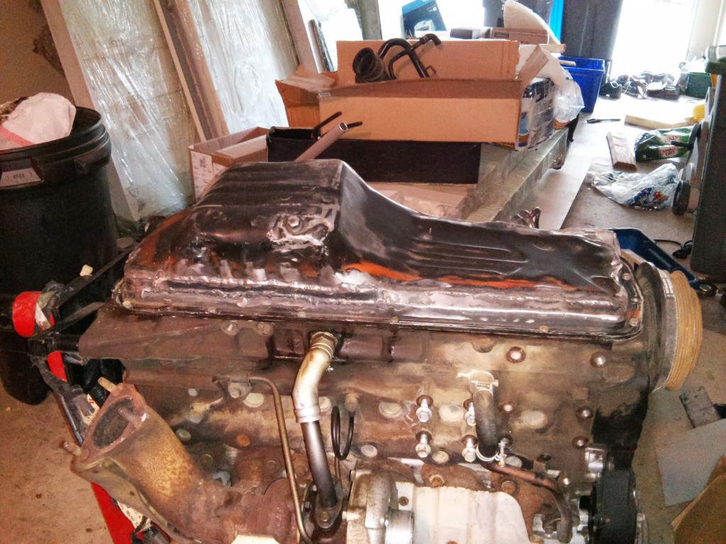
Now perhaps this solution is obvious and need not be documented, but I thought I'd throw some pictures up to show that it's possible anyways. Sorry there aren't more pictures, I wanted to get it done and the camera sat at the wayside. Step 1) Cut off pan close to the flange. Now you can cut parallel to the block, but that will result in a reverse pan tilt when it goes back on backwards. I opted to cut parallel to the bottom of the pan. This means taking off about an inch more on one side. Here's the flange once that's done: Step 2) Cut out the baffling step 3) Measure approxiamate sump height from engine block. I believe I used 3 pieces of wood I had lying around (2 the same height sitting on the block lip. step 4) Cut sump off. Use a tubing cutter if you can to avoid blasting any media down into the screen if using an angle grinder. You could also use some sort of plug and shove it in past the point where you are going to cut the tube. Step 5) Using your measurement you made above rotate the sump and tack it when it's about the same pan depth. You can even go a little bit deeper if you want, but your pan will be a touch deeper too if you do so. You can use your imagination for this step. You can be lazy and make 1 tack, then bend it till it sits where you want it. If you do that you'll have to fill a gap when welding. OR Hold the sump where you want it and try and make note of how the angle needs to be changed if at all in order for the flanges to meet perfectly. Then shave down one side till they sit nice and flush. Tack, then weld er' up. Also make sure this does not leak. I slathered mine with jb weld but was already pretty confident they were solid welds. Step 6) Prep baffle. Since the baffle was originally facing the other direction, the louvers are now the wrong direction relative to the windage in the engine. I assumed they were faced a certain way for a reason. I may be wrong on this, and they were stamped like that randomly, but I didn't want to chance it. So i just took a large screwdriver and bent all the louvers in the opposite direction. I'm OCD like that. You also need to notch out the tube portion of the baffle so that the pan can be installed easily. step 7) Tack up the baffle where you want it to the flange. Rotate the engine to make sure it doesn't interfere. This is why it's redneck style in that i used 4 plastic bags to seal the engine bay while tacking. Plastic = dumb. There was only a couple burn holes in the bottom layer during this step, but that means a few nuggets of metal down in there somewhere. I eventually rotated the engine over and did a full flushing with a solvent and air wand. More on that later. Ideally you'd want some sort of leather or flame proof fabric. Woven fibreglass perhaps? Alternatively you could secure it with 1 minute epoxy, then remove it and weld, or even use a few angle brackets and screws. Step 8) Setting up the pickup-pan clearance. This part is mildly difficult, but again just requires a little creativity and ingenuity. You'll find that with the pan flipped it will not meet all edges on the flange side. It will actually require a 1" strip or so on the side closest to the pickup (see photo in following step). To set the gap I simply used a 1/8" spacer sitting on the pickup as a guide. The pan will sit on the backside edge aprox flush, but it will otherwise float in mid air and rest on the pickup so you know your pickup height is close. tack weld the backside edge and tack a few brackets on the front to hold everything in place. Step 10) Remove the flange from the engine. Screw it down something sturdy (old piece of countertop or maybe a piece of 2x12 would be wide enough). Step 11) Tack weld the backside edge every inch or so and you can use a mallet to bring to two pieces close together. Here it is back on the engine. I used some clay on the pickup this time to make sure it was still sitting close. Step 12) cut a filler piece for the gap on the short side and weld ER UP! Step 13) Check for leaks, or if lazy just slather all welds with JB weld. Step 14) Thoroughly rinse pan with solvent or whatever else you want to clean it. Then blast with air to assure no welding bits in there. Step 15) Paint and enjoy! I'll try and post some better closeups of the pan on it's own. For now, here's a mess of my garage and the RB awaiting Test fit. Red Wrinkle paint valve covers and all. Engine and Freddy Manifold:
-
I guess i was vague on what the vise grip was doing. I used it to lock the steering shaft inside the engine bay just above the rubber coupler. I was trying to determine where the play was coming from. I had first thought it was the rubber coupler, then thought maybe my rack was worn, but after ruling both them out I locked the shaft post firewall and still had the same play. Then a little web searching led me here. I wonder if many users chalk this play up to that rubber joint or there rack when it might be a common issue for the spline joint. Can't wait to get it back on the road with a tight steering setup (once the RB goes in!).
-
My 260 exhibits this symptom as well. roughly 1/8" - 3/16" of play on mine. Instead of using my hand to lock the lower joint, I used vise grips and really locked that shaft in place to which i found out it was not the weak link (pun intended). Not sure I want to go the JB weld route. I was thinking about wrapping the splines with something that will take up the play. Something with good compressive abilities. One thought was some fine steel wire down 3-4 splines on one side of the receiver to really force the splines over into the grooves on the opposite side. Another idea would be teflon tape as it's fine enough to slide in yet I think by design is not meant to break down/compress too much (it is meant afterall as a seal on threads). Also thought of using RTV. While it is a soft material, it is pretty tough stuff. Given the surface area it has to work with might hold up and at least take up a large portion of the slop. THe worry with that would be that over time it would break down and crumble out. I'm going to try teflon tape first to see how that goes as it's easy to remove. Will let you guys know what I try and how it works out.
-
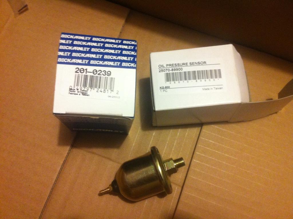
Hi there, So I'm posting this up because I couldn't find it in a few hours of searching on all the various Z sites. There's a bit of misinformation on which oil pressure sender to use and claims that only the original will work. Here is what I have found (which is also missing from all the datsun service manuals). The stock gauge reads roughly these readings at the following impedances from the sender. 1/8" below 0 psi - infinite ohms (open circuit). 0psi - 90ohms 60psi - 25 ohms 90psi - 12 ohms I could only check these as i only had a couple 12.5ohm resistors to use. Now I just bought the most likely candidate I could find on rockauto. This happened to be: BECK/ARNLEY 2010239 (201-0239) Oil Pressure Switch CAD$ 14.84 CAD$ 0.00 1 CAD$ 14.84 With a hose and my air compressor I measured the impedance at a few different pressures... 0psi - 88 ohms 20 psi - 44 ohms 60 psi - 25 ohms 90psi - 12.5 ohms Yes, the sender is VERY VERY accurate to what the gauge reads. Now a few things about the gauge...probably not good for a performance situation, but maybe usable to detect if your engine is getting weak (provided your sender stays in good shape). It is VERY slow to settle to the proper pressure. With the signal wire shorted to ground, it will sweep from 0psi to 90psi+ in roughly 10 seconds. Because it is a heated strip indicator and not a motor, measurements tend to go 90% to their location in 20% of the time, but take 90% of the time to travel the last 10%. Just keep that in mind if you want to aproximate what PSI you have at a given RPM. it will likely take over 10 seconds for a PSI reading to be close. Anyways, this gauge was from an early 260z, but I suspect other s30's apply. this is more a reference post rather than a helpful DIY, but good for those who want to diagnose an inoperative faulty gauge.
-
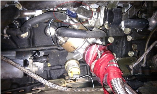
You get this resolved? As was mentioned, the purple plug under the IM is where the air regulator is. This is a cold start valve. It needs to get power when the engine is on. The fuel pump relay is a good place to get power for it. Aqua colored wire = switched 12v. Black = ground. I don't believe the wire gets hooked up in the stock harness.
-
run return back to surge tank. Reason being, if the high pressure walbro out-flows the low pressure pump, it could drain the surge tank defeating the purpose. Though there also needs to be a return from the surge tank to the fuel tank as well...make sure this a decent size so the surge tank doesn't become pressurized. Mark
-
I went with a Stock Skyline GTR oem intercooler. I believe it's 24x12x2.5" core. The end tanks don't fit, but there's enough material and end tank there that I can cut off the tubes and reweld at the proper angle towards the default routing holes.
-
Looks like it's going to fit great. I'll get some pics up as soon as I can. Just got married and the house is a little crazy...plus working on cabinetry stuff for new place. This project has taken a back seat, but I look forward to getting it going asap. Fire up the garage heater and go! Mark
-
This is a legitimate concern figuring ebay. That said, I've been quite impressed by most of the ebay intercoolers and whatnot I've got. It's nice that it's all aluminuim as well, so if it needs a repair it's just a matter of welding it up. It arrived yesterday, and I just need to pick it up from the states (I'm in Canada). Will let you guys know how it looks in there. Mark
-
The point was to save costs. The mckinney one is what...$300-$500? This was roughly $110 shipped, $30 for a Volvo fan and relay. Add in an aluminum pan to build a shroud a couple brackets from a junkyard, and I should have a pretty good cooling system same side for under $160.
-
Other issue is that it's outputs are 1.25" vs 1.375" (1 3/8"). I'll likely just weld a sleeve over it or something.