
mtnickel
-
Posts
335 -
Joined
-
Last visited
-
Days Won
5
Content Type
Profiles
Forums
Blogs
Events
Gallery
Downloads
Store
Everything posted by mtnickel
-
I wondered the same thing about the braces. Then a little research revealed all the RB26 owners are unable to mount it at all anyways since the holes don't exist on those blocks. Since my search didn't reveal any issues about flexing transmission shaft or pinion bushing wear or any problems, I assumed it's probably fine to leave it off. It made me especially frustrated since I fabbed my own pan but failed to mock those up in the process and didn't leave clearance for them. Oh well. Mark
-
Mods can delete. This is a repost as now seen in Non-tech section. My searches for roadkill and motortrend didn't come up. My apologies.
-
For those who haven't seen this: Just discovered these "roadkill" guys a couple days ago. So much fun.
-
This has been covered, but I'll bite. Sure you can mount the VLSD into your Long nose, but it's then finding shafts that will work with that carrier that is the hard part. The VLSD center typically uses one shaft that actually has an extension stub that engages into the LSD section. Without it you won't get any limited slip action. You are not able to use the VLSD stock stub axles either since you have no way of adapting them to your 4 bolt half-shafts. Read the Drivetrain FAQ thread.
-
New to the RB, need help figuring out internals
mtnickel replied to Da Fisch's topic in Nissan RB Forum
I second this approach. These engines have been known to handle 400whp+ without too much trouble. The tolerances and build quality that come out of the factory are exceptional. I read of far too many big builds that develop problems early on and read of many many shocking stories of big HP numbers on stock blocks that last a fair amount of time. Stony (a member) for example, was running over 600whp on an RB25 stock block (albeit with NOS). He's going bigger now, but it is just a testament to the quality of the stock build. One thing I can say for certain though is to have it professionally tuned. That will go a long way towards longevity. Good luck on the build! -
Old school AZC Coilovers
mtnickel replied to stony's topic in Brakes, Wheels, Suspension and Chassis
a1racing has 3 different sized tubes...these would fit I believe... http://shop.a1racing.com/cok12452-h.aspx they also have 7" sleeves if you want. -
Budget Coilovers with Stock top-hats
mtnickel replied to mtnickel's topic in Brakes, Wheels, Suspension and Chassis
I would be sectioning struts, so I would just cut the sectioned piece into 120 degree pieces (3) and weld them around to suit. And the eibachs are probably just fine you're right. So I will keep my eye out for a good set of used springs or just a good price on the ground control kit. -
Budget Coilovers with Stock top-hats
mtnickel replied to mtnickel's topic in Brakes, Wheels, Suspension and Chassis
True enough. It's only really worth it if you can get a really good deal on springs. Additionally, you can run, arguably, a better spring like hyperco's or swifts. -
Camber change after 1.5" drop?
mtnickel replied to mtnickel's topic in Brakes, Wheels, Suspension and Chassis
Thanks for the input guys. So long as the alignment won't be off to the point of really bad tire wear, it's probably fine for now. I think pushing in the corners is probably better for me to start as this is my first RWD car and most powerful. I was only asking now as the engine bay is going to be painted this week and I wanted to finish off any additional metal work before it goes to paint. I can always do bolt in plates or LCA later. Mark -
Camber change after 1.5" drop?
mtnickel replied to mtnickel's topic in Brakes, Wheels, Suspension and Chassis
Is there any particular reason I couldn't sketch out a template and just elongate the stock strut mount points by maybe 1/4" in the direction they need to go (1/4" out in the rear and 1/4" in on the front). I realize it could get close to the edges of the metal tabs up there, but I could reinforce those as well. Mathematically that would give about .75* of camber change. Now maybe this isn't enough to justify it, but thought it was worth a thought. My predicament is that it's just a street car where I want to keep the stock top hats for less noise, yet I also am trying to do as much fab work myself to save on parts (thus eliminating camber plates and expensive adjustable arms). I could perhaps do the lower control arm pivot relocation as well, but that seems like guess work trying to get the camber correct. Regards, Mark -
I did search on this but couldn't find anything, so excuse me if this has been covered. Does anyone know how the s30's camber changes after a 1-1.5" drop (73 240z). I looked for anyones alignment results with either stock or any sort of drop and came up with nothing. I know some cars take to lowering better than others depending on the geometry of the arms. My hondas for instance, have always been very close after mild/sport drops. Also, I know camber plates are popular, but is it not possible to just slot the stock bolt holes to get some camber change? From a few measurements it looks as though there is at least 5/16" of clearance to go inward. The strut top hat material is also pretty thin and can be massaged if a little more is needed. This would be for a street car of course. I know the racers typically go the plate route to run much more aggressive camber. Basically I'm building a car that is 95% street driven and will be doing a mild (1-1.75" drop) and am wondering what similar people have done for camber and alignment changes. Regards, Mark
-
Coilovers without sectioning strut tubes.
mtnickel replied to richie2619's topic in Brakes, Wheels, Suspension and Chassis
What were you alignment results with the stock top hats and the 1.5" drop? I personally am doing the opposite: sectioning tubes without camber plates. Also note that your spring to wheel interference will only be raised by the same camber plate removal amount. Coilovers also allow for more wheel room because people either run an 8" spring (which movea the perch up) and because the springs are narrower 2.5" ID -
I think I've come up with a final design: Found this on a new zealand site. It's for a toyota all-trac (which is a celica 4wd I believe). Anyways, I like the overall design. The labyrinth entry provides good cornering/accel resistance, but they modify it with a roughly 1" block at the entrance that has only a small hole entrance. This stops the pot from emptying out the highest point (as was shown in my initial pictures). It will be a street car first and foremost, so 99% of the time it's a non-issue anyways. But I believe if and when I get into Autocrossing, it should have decent fuel surge protection.
-
Budget Coilovers with Stock top-hats
mtnickel replied to mtnickel's topic in Brakes, Wheels, Suspension and Chassis
Ya, I will likely do the sectioning of the struts anyways. I have all the tools and know-how to accomplish it. My only push back was the possibility of a weld penetrating too far and causing some headaches, but I figured I could use the cutout to do some test welds. Thanks for chiming in 280zcar. I didn't realize the top hats had reasonably flat spots there. Without the need for adapters then it seems like it could still be a good deal. Not much more the 330 shipped or so. Plus you get to pick the exact spring rate you want. Will keep people updated and maybe post a few pics of the top hat modifications if I go that route. Regards, Mark -
Budget Coilovers with Stock top-hats
mtnickel replied to mtnickel's topic in Brakes, Wheels, Suspension and Chassis
Only issue is the bone jarring spring rates of 300+ coupled with a short sleave and short spring. -
Hey guys, So from my searching on here, most don't recommend camber plates for a plain old street car. I'm going for a good handling street weekend cruiser with occasional spirited driving (and definitely the possibility of auto-crossing for fun). Most say the camber plates and lack of isolators transmit a LOT of noise into the cabin...not something I'm fond of. So the info isn't that clear on how to adapt from the common coilover kits to stock top hats. But from another member on here (280zcar) I've seen it can be done on a budget with just generic coilover sleeves. So what do people think about the following: 1) Use a standard 2.5"ID coilover sleave and perch. 5" threaded sleave (could get 7" if desired) http://shop.a1racing.com/cok12450.aspx $15.53 X 4 Adjusting nuts http://shop.a1racing.com/cok12460.aspx $12.87 x 4 = $113.60 + shipping 2) It's unclear whether a 2.5" ID spring will work with the stock top hat, so something like the following would probably be necessary: 2.5" to 3ID Spring adapter (stock spring is roughly 3" ID, 4" OD) http://store.resuspension.com/product.php?productid=18887&page=1 $17.85 x 4 = $71.40 + shipping EDIT: I failed to remember the 240z uses steel spring perches. This kind of adapter will not work into the top hat. Disregard the rest. 3) Pick your 2.5" coilover springs and go! Of course you will need to do your due diligence on what length and stiffness to get to get you in the ballpark for ride height. Likely $200 for springs. Coilover and springs to suit driving style in under $400. So does anyone see any downsides to doing this? I have an early 260z which has the front spring perches in a different position relative to the 240z. This means getting my ride height right is going to be a big question mark not to mention the front may sit a little lower with an RB25. This seems about the most economical way to do it. Note that this would obviously require cutting off the stock spring perches. You wouldn't necessarily have to section (depending on how much you lower the ride height). I'm only going for a mild (1-1.5" drop) drop so it wouldn't be absolutely necessary. EDIT: I see now that the ground control's are more or less exactly what to use. That said, I've seen conflicting info on how it interfaces with the stock top hat. Anyone have any insight into that? Some people machined the aluminum top hat, others used spacers. Looks like it comes with spacers.
-
I already have an external walbro 255 and am keeping myself to the smallest budget possible. I know there are plenty of solutions to buy but was just looking to create some discussion on what a DIY'er could do with just a little sheet metal and welding.
-
From all my research, a true swirl pot may be the best solution. With the return just dangling into the pot there could be some splashing/turbulence. I'm going to see if I can somehow replicate an oem swirl pot such as this: The venturi inlet will be the most difficult part, but I see it as doable.
-
NOTE: Mods, this could be moved to Fuel Delivery. Hi guys, Yet another thread, but I feel it's useful to the community for both RB users and fuel injection alike. Does anyone have any insight on what the best fuel tank baffling would include? I know trap doors are recommended, but I'm more doing this on a budget. So far I rinsed my fuel tank 3 times with soapy water. I then cut it open with a jig-saw underneith. I used cutting oil and made sure to go slowly as not to create enough heat cause sparks. I was pleasantly surprised to see "Alied Radiator 6/94" written on top side. So looks like it had been given a solid cleaning and red-coat on the inside. The exterior was also covered in a thick paint job though it was peeling in many spots. While cleaning the tank though I did notice something odd. When flipping it and turning it to rinse all areas I noticed the stream coming out of the return line was quite weak compared to the feed line (even though they were the same size). From blowing in it as well it seemed quite restrictive. A little investigative work revealed that the outlet had been repaired or something and I believe a large amount of Braze was left in the tube. I heated it up and pulled it out once the solder melted. I replaced that with a 5/16" brake line which should suffice just fine. I ran it long enough to feed back to exactly where the pickup is: I had terrible luck getting the solder to stick no matter how much i cleaned the area or used flux, etc. No fun. I ended up cleaning one final time and just JB welding it in. The flange is 1" deep so I'm not too concerned about strength or seal. Anyways, onto the discussion of tank baffling. I'm looking at baffling the pickup and return. I got this idea from a fellow member Xander. Here's what he did: http://forums.hybridz.org/topic/115077-280z-fuel-tank-vs-surge-tank-for-efirb-swap/?do=findComment&comment=1078218 Basically a box with an L entrance. I'm not convinced the L provides optimal fuel containment. Aeromotive typically recommends a box with just 2 - 3/8" holes drilled into it. The L shape is beneficial because once it hits a point it will keep all it's fuel. The small hole design is good in that the level will be higher but will drain down over time. Not sure how long of a corner we are talking or how long it will take for fuel to drain out the 3/8" hole. Consider the following comparison.... The L design would probably do better for fuel heat soak as well. Anyone have any thoughts on the best style of baffle? The baffle will simply be welded to the square that was cut out and the the square welded back in the tank.
-
This is true (and often stated). It's things like: Fuel: Surge tank, new fuel pump, all the fuel pump fittings, wire and relays for the fuel pump (as it's high current), some new hoses, fuel filter. Easily $250-$300 all said and done. Engine wiring tuning: Bound to need more relays, various wire, electrical tape, heat shrink, random connectors. Most then opt for either stand-alone or swap to Z32 converted Nistune. Maintenance items: New water pump, timing belt, gaskets, alt belt, spark plugs, figure a few sensors are broken. Easily $350 Cooling: You can try and use stock radiator, but you will at least need a few hoses/extensions, etc. Plus adapters/new hoses for heater core. And again with clamps, fluids, flush kit maybe (for that engine that has been sitting). Turbo: Intercooler, mounts for it, silicone couplers, clamps. This can be big bucks. Gauges: boost gauge, wideband o2 sensor. I'm stopping here as I'm getting a little worried about all the money I've spent, but this really goes on. I've spent over $300 just in random paint, primers, grinding disks, in the last 2 weeks on doing mild repair work.
-
Question on Fabricating Transmission mount / Driveline angles
mtnickel replied to mtnickel's topic in Nissan RB Forum
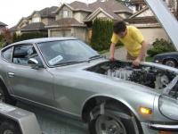
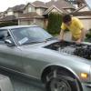
Pics as promised: Leveled the engine according to the timing belt slit. Not sure exact slant, but i was happy with it: 1/4" plate on engine (and same plate was put on the generic Poly mounts. I believe they are for old jeeps). Getting the tilt on the engine and having it not move: The other front support was just 5/8" plywood between the oil pan and the steering rack. Also not the wood that counter's the strap. That positions the pulley bolt exactly between the two frame rails (or maybe 1/16" of the passenger side). Mount done from cardboard template (I wrapped my tubing to make these so I can slide them over the tubing to transfer the angles). Then the distance between the 2 pieces was measured. Then put back on the rail to be cut: I erred on the long side in case I needed to tweak the angles which I did. Here is the passenger side complete: They were only tacked but will be taken to cousin welder to be TIG'd. Here is the 2 of them: They actually angle forward a little bit as I wanted the engine as far back as possible both for balance and to make room for fan and rad. To my dismay the driver side tubing was 2.5mm and the passenger side was 3.0mm tubing (somehow the scraps I got from the metal place weren't the exact same and i didn't notice till after the mount was done). Hope 2.5mm tubing is strong enough. I may add a few angles for support. There's about 1/2-5/8" between engine and firewall and about 1/4" between valve cover and hood support. On to the transmission mount: There are minimal pictures of the actual driveline setting, but it's more or less just using the angle gauge and raising or lowering the transmission tail until the angles match. I got them within .1 degrees. I also used a rigged up laser system to get the left and right correct. Here's my laser which is a combination of a socket (that fits the laser) and the magnetic end of snap on trouble light. (cap not shown unfortunately. it's just an aluminum cap with an imbeded magnet) slipped over the trans output shaft but i had to put a socket on the diff not to get a nice flat surface there). Found Center: I ended up actually measuring where the dot was in relation to the back of the shifter opening so I could reference it when moving the trans tail. Reinforced trans wall with 2mm plate. Here is the wall preped. Note i also cut away the original mount support. It is necessary on the passenger side (for the speed sensor) but not really necessary on the driver side here. I drilled the original 260z mount for 2 studs (stock had 1 in the center, rb mount has 2 spaced apart). Also cleaned up the stock ears. By cutting them as close to the body as possible they retained nearly the correct taper (as the tunnel gets smaller). Then I cut the ends off the mount: The put it all in the car: You can see the 2mm plate here as well as the taper. They needed to be notched in a few spots to give better clearance for the transmission webbing. The driver side mount was positioned as high as possible to allow room for the exhaust. From here it's just a matter of making sure the tail is exactly where you want and then bridging the 2 pieces together. But a few more pics first: Alignment of shifter...It's shifted towards the rear about 1.5" which i actually like. puts it about in line with the steering wheel and I prefer having it a touch closer. (sorry the shaft isn't on but it's similarly placed to the lower hole. Not too much clearance between the trans vent and the stock fuel lines. This was when the trans was at the higher angle. It's probably another 3/8" lower than this now. This was after tacking in the placement pieces: Then after it was filled in and reinstalled: YESSS! Finally it sits on it's own footings!!! Removed and then painted it up all nice. Will still have to weld the ears on a bit better as well If you have any questions just ask! -
Update (Feb 2014). AE86 rad installed. I updated my other thread on this as well but putting it in the build thread as well. Finally got around to installing this. I'd say for the budget it's a pretty good option. I this into it: $110 - Rad $7 - 1 3/8" pipe ends to be welded (or JB welded) over-top of the 1 1/4" outlets $5 - Stock toyota rad top brackets. I forget the model but some late 80's or 90's toyota. Cresida maybe?. - Lower rubber mount from random car with rubber donut and hole (with $5 above). Here are the parts in question: the one Rubber donut on the left was the proper toyota one, but all the toyota mounts were welded to the chassis so I couldn't pull them. The one on the right has a match that isn't seen here. The hole was too small to fit the bottom studs. To enlarge it I took a Pulley bolt that was the right diameter, heated it up red hot with a Oxy/Ace Torch and ran it into the hole. Worked like a charm. Otherwise it's difficult cutting rubber. Dimensionally it fit like an absolute dream. First I checked how much hood clearance I had using cardboard. Once I had the rad up though it was clear that there was over 1.5" of clearance so I took the cardboard off so it didn't get in the way. The upper support is a tube so I couldn't weld a nut on the underside. I resorted instead to drilling all the way through and welding studs(bolts) to hold the upper brackets: The rubber donuts are seen below. I actually mounted them second. I jacked up the radiator until it was nice and snug to the top brackets. Then I positioned the lower and tacked them to the lower rad support. Here's how it came out:
-
Update with the install. See first post.
-
It won't be as simple as drilling new holes. The flange ends are not symetrical. Also, if you flip the pickup around it will point to a spot that's not under the engine. The only way to use the stock pan is to cut off the flange and re-weld it. Additionally, you will need to cut and re-weld the pickup but at the same time making sure its positioned well inside the sump area. That likely involves trimming the baffling inside. While $389 seems like a lot, even after I've done mine by re-welding (flipping) I still think it's fairly reasonable. You really just have to weigh the cost benefit to the difficulties you'll have of: setting up the sump correctly, making sure the sump weld doesn't leak, making sure not to warp the flange when welding, risk of it leaking meaning a 2hr RE-RE (plus another gasket or RTV), painting it so welds don't rust, setting it up so that it's sloped correctly (reversing it will put the pan slope opposite of what you want). The list goes on. If you are really confident with a welder and have some spare sheet metal as well as an engine stand (so you can work on it the right way around, then go for it and flip it. Otherwise you have to fork out the dough. The pan and mounts are the most essential part of the swap. Good luck whichever way you go.
-
Me too. I need the throttle body and all the parts off it (sensors, etc). I am a little closer in BC, but again, it's just the plenum. Let us know exactly which parts you need. Mark