
mtnickel
-
Posts
335 -
Joined
-
Last visited
-
Days Won
5
Content Type
Profiles
Forums
Blogs
Events
Gallery
Downloads
Store
Everything posted by mtnickel
-
To add to this thread, I've had a little more seat time with my 3.90 and rb25 combo. I'd say it's probably a good compromise for those who are looking to do a little track as it'll go through the gears a little more. For a street car though (which mine mostly is), I may have likely preferred a 3.70. Only reason being, my average cruise speed around 70-75 is just a tick over 3000rpm and would have been just perfect I think (2700-2800) with a slightly lower ratio. Performance wise it's nice though. And I'm amazed at how well the 3.90 with Torsen and 205's hooks up. I mean, probably only running around 250hp right now, but plants Great!
-
Some are just 1 phillips screw yes. Some are mounted from behind however and the entire bearing needs to be pressed out the other side. It gets quite intensive.
-
Z32 doesn't need a harness. You do however have to add just a couple resistors inside and a couple wires inside the ECU (mainly fuel temp sender (since we don't have one) and stub out the knock sensors (cuz RB ones are too sensitive and false trigger), and I think EGR or FICD needs a wire moved). I used the exact same ECU. I had an eprom emulator already (Moates ostrich), so all I needed was the ECU ($40 for NA board), socket the board ($10), get a consult cable ($20), and get the nistune license ($200). Otherwise, the Nistune board/package is a better all in one solution for $515 AU = $406 USD plus whatever the Z32 ECU costs. They are making the software better all the time as well. They now have an injection multiplier which makes injector resizing simple. Nistune is however a just a hopped up stock program mod, so it doesn't have quite the full features an aftermarket ECU would have (little support for boost control, meth injection, launch control, 2-step rev limit, etc.). I'm almost ready to get on the dyno with my RB. Just need to iron out the LS2 coil swap finishing touches, and get my interior back in.
-
Just find info on a TA45 for more details.
-
I was close. Further research on the model number you gave resulted in this: Engine, Valves, Horsepower, CC (18.6L engine), and turbo model DS2840LE 10V 700 18600 TA45 710223-0001 It's a BIG turbo. Probably wouldn't spool till over 5000rpm on a 3L. Might do OK on a big v8
-
Can't tell you exactly what it is. The compressor is a lower trim BIG wheel. Similar to a GT35r but with an even bigger exducer (meaning probably more intended for higher pressure ratios (read Boost levels). HP supports probably between 400-600hp (based on wheel size/trim alone. Design of wheel could greatly affect this number). It has a BIG Exhaust housing however so will probably not spool well on a smaller gas engine. If i had to guess, it's a diesel based turbo meant for a big (7L ish) engine. Maybe ask instead if it would be ideal for your application, not just "identify it". Unless of course you are just trying to sell it. Regards, Mark
-
As a side note. If any rb users here have their turbo off or the part available, would be able to measure the orifice diameter on the stock feed line banjo bolt (turbo side bolt). Just wanting to know how much Nissan decided to restrict the feed to this turbo so I can do the same on other build.
-
Hi guys, I know this won't be the MOST informative thread, but i thought i'd get the info out there. I've got what I presume is a S2 RB25DET stock turbo. Upon receiving it, i checked for axial shaft play. Wah Waaa, it had about 5-6 thou of axial shaft play. Thought it was a junker (and also suspected my engine may not have been well cared for if the turbo was cooked). Everywhere I read online led me to believe next to No axial play was acceptable (usually less than 1.5 thou or so). What I didn't realize was that the S2 turbo I have is actually a ball bearing Centre! I figured since the turbo was junk, I may as well attempt a rebuild. I know they say these are often unserviceable, but I thought I could get to the thrust bearing only possibly. I didn't take many pics, however, here's the compressor wheel (I have the plastic wheel version). I did mark the nut, turbine shaft and wheel for alignment. Took the backing plate out... And look what we have here!!! A Ball Bearing Centre!!! Ah, so now that I know it was ball-bearing, and it dawned on me the axial play limits of a ball bearing turbo might be different. A quick google search and forum posts indicated that even ball bearing turbos should have no axial play. Now, I figured, might as well check the service manual! (should have done that first). Reading the manual showed me the axial limit for the R33 is: .12 - .2mm That's .0047 - .0079". Now, my 5.5-6 thou doesn't seem so BAD! Dang, I just disassembled a turbo that was perfectly fine!!! So regardless what you read on forum XYZ, look at your service manual, or ask the turbo manufacturer. I think I found some ball bearing turbos were taper design and so also shouldn't have much play, but the garrett design however might have some, such as this. While i and it apart, i took a few readings and pics: Plastic wheel factory balancing... weight (didn't come out 32.5g) evo3 16g weight: (I think about 56.5...i can reweigh, mad the photos didn't come out). Small 16g, rb25, evo3 16g inducer 48.3 Exducer 66.6 I was most impressed with how incredibly thin the plastic blades were, as well as how light the whole assembly was. It felt like it had very little mass. I know these turbos aren't POWER monsters in that you can't crank the boost on them, but just thought it'd be nice to get some info out there. I plan on cleaning it up nicely (had a lot of carbon/sludge and such from PCV circulating) and then using on my honda accord build. I was originally gonna use a small 16g turbo I had, but this seems to fit the bill better as far as spool and efficiency for a 250-280hp build. Good luck with all your RBing! Mark For other RB turbo info: All R33 RB engines are said to have a Ball-bearing centre (perhaps some R32, though I can't confirm). Series 1 typically came with aluminum (alloy) compressor wheel, ceramic turbine Series 2 typically has the shown nylon wheel and ceramic turbine R34 Neo has same nylon wheel and ceramic turbine but turbine housing is slightly bigger (labeled op6). Rumor is there is a Neo turbo as well that has a garrett branded compressor housing that has alloy compressor and steel turbine wheel. I have not seen definitive proof of it however.
-
What is your horsepower goal? 3" all round intake piping is pretty large. May also restrict your intercooler choice and fitment for bends and such.
-
Don't know about the fuel rail, but I noted that the Greddy type plenums had 2 recesses machined for both top feed and side feed injectors. I was originally going to stick with side feed injectors, but when i mocked them up i noticed that they don't actually site very well in the machined holes. Yes the seals are snug, yes the injectors seal into the seals, but they sit much to high up in the hole. Considering the spray typically fan's out at a 45* angle or so, i was concerned it was going to hit the rim of the lower recessed hole. This would ruin atomization and cause raw fuel to drip in. I opted instead to pickup a GTR top feed rail system and injectors. It's a bit of a pain, however, because you need to rewire harness, make properly sized isolators, and also wire in a resistor pack for the injectors (if using GTR 440 low impedance). Though I"m not sure if aftermarket ECU's support low impedance injectors natively. Of course, there is a final solution whereby you could probably drill out the lower lip of the injector openings and maybe bevel the backside with a die grinder and alum bit to make sure the spray pattern will clear. Hope this isn't too technical and helps, as I feel it's something many users could over look and then wonder why they have drivability problems.
-
The rubber intake boot that attaches to the turbo has 2 inlets for both of these connections. There was however another hard metal pipe that brings the connections closer, but I suppose you could somehow do it with a tube. As a note, if you're using the stock ECU system with the MAF sensor, then it's important that you route these back to a location before the turbo, but after the MAF. The Bypass valve will be slightly open during idle and higher vacuum, this results in an air leak where unmetered air gets into the engine (unmetered meaning air that hasn't flowed through the MAF sensor). This will in turn cause the engine to run lean. Opposite happens when it operates as intended (to bleed off turbo air pressure), the turbo sucks up tonnes of air which the MAF senses, but then it's routed back out to the atmosphere instead of the engine. As such the ECU triggers the injectors to fire way more than is needed resulting in a high rich condition (often can cause engine to cough, burble, flames out back, etc). Ricers always route them to atmosphere for the ricer sound only to find strange drivability problems between shifts. The Crankcase vent system is also part of the metered air system as there is a hose and valve connected on the side closest to the intake manifold that leads into the intake manifold that is intended to constantly cycle the air out of the crankcase. However if you convert to a MAP (manifold air pressure) aftermarket ecu solution, none of the above is a problem. If you need the stock rubber intake hose, i have one, however I don't actually have the stock hard pipes anymore as i scavenged bends and such to lead to my custom hard pipe intake. Final note, the stock rubber inlet hoses are probably only good to about 280-300hp as higher flows can cause them to suck shut. There are some DIY's to reinforce them however. Good luck with the build!
-
I also have a whole heater box/core assembly. Not sure if it's good or not as it came with my project car with several rubber maids of parts. From looking at it, it looks quite clean and minimal corrosion. Could probably pressure test it if need be. Mark
-
RB25det Turbo Fitment with stock manifold
mtnickel replied to theczechone's topic in Nissan RB Forum
I have a stock turbo with 4 thou axial shaft play. Likely close to the end of it's life. If you do decide on a high flow option (modified stock turbo for more power) I could send mine in as a core for you. That said, the 2871 often does not come stock with a t3 style turbine housing. The 3071R often does come with a t3 housing. What you are after is a turbo with a T3 turbo flange (as that is what the stock one is). If you are purchasing new, you can often get the turbo housing you want from the supplier. ie. http://www.atpturbo.com/mm5/merchant.mvc?Screen=PROD&Product_Code=GRT-TBO-022&Category_Code=GRT Is your power goal wheel horse power (WHP) or just crank). -
After going through all the trouble of welding into a stock tank, I can easily say I wish I had gone a similar route to this one listed. I welded in a baffling system, had to replace the return to drain into the same baffles, and then also had to deal with all the fiddly pre-pump filter, clamps, mounting fuel pump, etc etc. Having a tried and true simple drop in would have saved some headaches. I've even read threads (maybe not on here) of users just buying a junkyard tank/pump assembly from a nice modern car and bolting it in the same way as above. Good luck either way.
-
s30 blower motor upgrade w/pictures
mtnickel replied to 280zedxt's topic in S30 Series - 240z, 260z, 280z
I don't know much about these swaps, but how thick is the stock fan spacer. Just so you know, it's pretty critical that the clearance between the cage and the bottom of the fan box is not too large. I'd say you want it under 1/4". The fan needs to draw air in and throw it down the outlet. If there is too big a gap it will be sucking it self. Tough to explain, but just curious as to the stock spacer width as in your first picture there is a 1" depth difference from flanges to bottom of cage. -
Do you have a wideband o2 sensor installed? That will be the most important tool for tuning. An EGT gauge is also useful. More than likely you will need to have it professionally tuned. If you want to learn and are motivated, you could do a small amount of tuning yourself. I'd recommend to leave the wastegate lever completely open and perhaps only tune the vacuum portion of the map. I would 1) use the startup map they've given. You will need to use their tools in the software to calibrate for your injectors. Also will need to calibrate the injector opening time as well. Be sure to note as well if the ECU is compatible with low impedance injectors in case you are using them, and whether or not you need to add resistors. 2) Once running, I would imagine there is a scaling tool to move the whole map around. I would adjust the whole map (or scaling tool) so that it idles at the correct AFR. 3) Then you could begin to just get the Air fuel ratio's close. Hopefully there is a logging function where you can do some low throttle work and log the AFR's. Then make changes to the map and try again. You will very likely need a tuner however to 1) tune the boost portion of the map and 2) tune all the ignition timing. It's quite difficult doing the ignition timing unless you are experienced. You need to monitor for knock, tune for maximum torque in the off boost portion (for best economy etc). Possibly adjust timing around idle areas to insure steady idle, etc. Also, these engines can misfire a fair bit on stock coils. Will need to have someone around to know what that sounds like/acts like, as well as how to remedy (perhaps replacement coils, gap down plugs, colder plugs, etc). While you may like programming, an engine is a system of moving parts that need to be fine tuned. There is no control-alt-delete in one and incorrect 'code' (tuning maps) can result in a blown engine. As a youngster (teen), i went through 2-3 honda engines with my pathetic attempt at "tuning". Things that plagued me: - Assuming a basemap I had been given had "conservative" timing...incorrect, cracked ringlands, - Not monitoring/noticing boost creep/spikes...poor mapping in those unused areas led to a lean condition and again, blown engine. Good luck with the new powertrain! I too am an RB Z owner. Mark
-
And yes, I do have the most bitchin' Christmas lights in the neighbourhood...must've been the annual tradition of watching Christmas vacation.
-
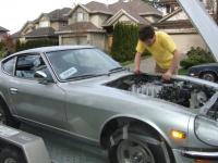
Update: Here's the rad shroud I was talking about. I got the idea online about doing a fibreglass one. First, start with the dimension shape you want to sit against the rad. I did this with MDF... Make sure to factor in the width of the fibreglass. Then I cut the diameter of the Radiator fan I'm using. Then I added some relief cuts so it can be pulled out of the fibreglass later easily. Also beveled the back side for smoother lines... Then wrapped with tuck tape so the fibreglass wouldn't stick. It stuck somewhat but definitely was not bonded. So use caution...could have even wrapped with tin foil or something like that as well. Finally wrap with stretchy fabric: Paint with resin. Note in the picture the red stick above and below; Because the shroud was to fit into a recessed space on the rad, i was not allowed to simple stretch to the edge of the wood. It would have caused a bulge and it wouldn't slip in. Instead, these sticks were screwed in to maintain a 1/4" flat profile around the exterior. Hard to explain, but when you stretch fabric (if you ever do) you will see what I mean (should you mount the shroud directly to the core and need to clear protruding end tanks). Note: Fibreglass off-gases for 48hr or more I believe. I shut my garage door after about 6 hours, and though I didn't notice the smell in my house, the neighbours did! (4 plex townhouse unit tied together). Was over the Christmas break, and they were less than thrilled :S. The units are vented weirdly and I'm guessing their unit has a fair bit of negative pressure and pulled many fumes through all the garage outlets. I digress... Once this step is done, you could do you buildup with fibreglass matt or fabric on the outside. would take 2-5 coats, depending on the stiffness you want and the matt weight. Doing it on the outside however will 1) change your outer dimensions to the rad, and 2) make the surface much more inconsistent and therefor harder to finish. I really liked the smooth texture once this was done and didn't want to mess with it too much. I therefore removed it from it's mould at this stage. I ground the edges of the back to release the rear piece: With a little finesse, got it out (notice i rounded over the outside corners as well: Then got the round part out. This was a little more challenging, and I would suggest if the only release agent you use is regular tuck tape, to use many more relief cuts. If the pieces weren't 10+ inches long, they would have been easier to wiggle out. Test fit: I then added 2 layers of thick matt to the backside of the mold. Sorry no pics. Finally, I mounted up the fan. I need a nicer spacer to cover the bolt in that one area. I used fab'd metal brackets on the other points to secure it. In hindsight, i should have incorporated brackets into the fibreglass mould (would have been as easy as securing metal or even 1/4" wood plates to the wood before stretching. Then incorporate then into the fabric stretch. That would change the contour a bit however. Alternatively then you could hot glue them to the completely mould and cover with fibreglass...use your imagination. I figured i had invested enough time however that I was content with a few bends in 1/8" stock and some gloss black paint. Geometery on this mount is far from ideal, but the other bolt takes the brunt of force: The lower ones are similar but with much better geometry. If you look close in the last photo, I also mounted mounted the fan relays. The fan is identical to the taurus fan, though I found on other forums by getting it from a volvo, you can often snag the heavy duty relay and harness - which i did. $25 for all. I'm only using on the low speed, but it should be plenty of cooling for our mild Northwest climate. Plus, the rad is sealed so well the the rad support that it all gets great cooling. I was shocked however at how hot aluminum rads get! So used to the somewhat insulated ABS ones on my hondas/toyotas/etc. Seriously very hot to the touch at operating temp (190* is pretty hot after all!). Shroud will be removed some day and bondo'd and painted. It's fine for now. Update 2: Made little bracket and got intake all installed: Fenders installed: Strikers fixed: So, if you do enough reading, you will see the main HARD clunk sound on door shutting is because there is a missing piece of rubber on the door side rotating latch. I didn't want to fiddle with glueing rubber to such a high wear item. I made up the difference in clearance by welding more material onto the striker: This greatly corrects the geometry so the second lobe rotates into the hold. Teaser! Seriously, how great is the S30 Design! AND NOW, Pulled it out all on its own power!!! Complete with concerned looking wife and all! Those are Konig Rewinds btw. Stance isn't even too bad with the completely unknown springs that were in there to start. Also did a drum refresh. Not turned, but new shoes and scuffed up the liners with emery cloth: Car now back in the garage awaiting issues to be resolved: That's all for now! Hopefully external waste gate mods not too far down the road. Along with interior completion. Ciao!
-
Also, yes, on factor spec dwell, they will be loads better than the stock coils. On factory nissan ecu's I believe dwell rarely reaches higher than 3.5ms, so they would obviously be just fine. It was more a disclaimer not to get them, set dwell (in aftermarket ecu) to the MAX of 5.5ms like some say is fine, and then blow your engine.
-
Reference: http://www.msextra.com/forums/viewtopic.php?f=131&t=48931 http://efi101.com/forum/viewtopic.php?t=6653&start=20 There were a few other places I read it, but can't seem to recall where. Apparently, the D514a don't have any protection and are a newer/more efficient coil (though not as hot as the 585)
-
1) The single coil just fired 6 times as often. It used the distributor to determine which cylinder to fire to. So yes, it should be accurate enough. Note I have not tested the current sensing tach personally, so can't say 100% that it will work. If dwell times (the length of time the coil charges for), or amplitude of current (due to differences in the resistance of the stock vs RB coil) are different enough, it may not trigger the tach, but based on the other users success, I can't see why it would not work. 2) I cannot speak to the accuracy of the early vs late tach's. It would seem logical that the newer design was better, but tough to say. I feel like I've read the 240z tach tends to be 'bouncier', taking longer to settle. If it's accuracy you're after though, I believe both units have trim pots where you can tweak the calibration of the unit. Good luck!
-
Thanks! There are many updates, but I haven't got around to posting them up. To come: 1) I fabricated a fibreglass rad shroud to use my taurus/volvo fan. Works awesome! 2) I got all the fenders and body parts back together 3) I got the 3-wire tach working (info is in another thread) 4) I insured it for 2 days for a few test runs! Ran fairly well. Cabin is pretty noisy without any carpet/panels in. Issues to sort out: The td05h-18g I used, while spools INCREDIBLY fast, is not gated enough. The GM style turbine housing I have is lacking in both wastegate diameter and flow path. As a result, I was getting rediculous boost creep. Even with the gate arm completely disconnected, it would build 20psi of boost. Guess that's what I get for going 3" exhaust, reasonably big billet 18g wheel, and an 8cm td05h turbine. I had thought since the subaru sti guys can run the same turbo on their 2.5L without bad creep issues, perhaps i'd be ok. Well I failed to factor in that they are often running 22-25psi of boost, and the more boost you run, the less wastegate you need. I even found some guys who did have creep issues too once i looked deeper. Likely going to see if I can get a shop to weld me in an external wastegate into the exhaust manifold. It's been done before. I wanted instant torque, but in hindsight, I think the td06sl2 20g may have been a better option. Ignition: I also picked up some GM coils (specifically D514a). I know there has been a ton of hype on the d585, and they are good, but I have also read that they have overdwell protection and if your dwell is set wrong, they will fire early wreaking havoc on your timing. So if you use them, make sure your dwell is less the 4.5ms (not 5.5 like some mention). I was having some spark blow out even at 8-10psi of boost. I think the cause was a cracked sparkplug when i checked, but I detest misfire. The stock coilpacks (sitting in a yard for years) are likely a ticking time bomb anyways. Hopefully pictures and updates to come. Things are a little hairy around here though what with the wife being 7 months pregnant and all...with our first child. (ha, after writing that; if it's hairy now, I'm in for a big surprise in coming months ). Later guys
-
Did you wire the car yourself? The 4 wire tach I've read can be used without too much trouble. First, here's a diagram of the stock configuration. It's important to note that the coil does not get power (+) from any other wire. How an inductive circuit works is that when the coil is charging and discharging, there are bursts of current going through it's power wire. The 240z tach reads those current spikes with it's inductive pickup (since when current flows through wire, it creates an electric field). Another member has written: "You can also use the inductive (current sensing) style tacho if you power the RB coils from the same wire that provided power to the stock coil. This is what I am doing with my RB swap." http://forums.hybridz.org/topic/80017-rb-zed-tacho/?p=759685 So what he is saying is that you need to run the power wire that goes to the coil-on-plug harness through the stock tach. Then it should be able to read the same current pulses. Again, I reiterate that you aren't just 'tapping' into the power line, but it needs to physically flow through the tach. Something like this: The only benefit to option 2 is so that power comes from the relay as it was intended, and not from the key. Perhaps you have specific fuses on coil power from there, etc. This should give you the right idea....i hope.
-
Also interested in a pair, likely with the speaker holes. Mark
-
The MSD 8910 should be internally similar to this circuit, though it will lack the pullup resistor. Maybe some have tried just the pullup resistor, and then just the 8910 or 8920, when really the tach adapter would need the pullup resistor for it to see the correct signal. On another note, if you're wondering how an ecu would put out such a circuit (with no positive wave), it would be due to it's internal construction looking like this (a "low-side driver/switch" since the low-side (ground) is the one being switched: If that Yellow region is not hooked up, then the output will only change from being connected to nothing, to being connected to ground. In case you don't know how a transistor works, it is basically a switch. When the switch turns on, the top and bottom wires allow current to flow through easily. When the switch is off, current is not able to flow through Q1 from top to bottom.