
mtnickel
-
Posts
335 -
Joined
-
Last visited
-
Days Won
5
Content Type
Profiles
Forums
Blogs
Events
Gallery
Downloads
Store
Everything posted by mtnickel
-
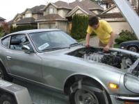
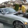
Made the engine and trans mounts: Leveled the engine according to the timing belt slit. Not sure exact slant, but i was happy with it: 1/4" plate on engine (and same plate was put on the generic Poly mounts. I believe they are for old jeeps). Getting the tilt on the engine and having it not move: The other front support was just 5/8" plywood between the oil pan and the steering rack. Also not the wood that counter's the strap. That positions the pulley bolt exactly between the two frame rails (or maybe 1/16" of the passenger side). Mount done from cardboard template (I wrapped my tubing to make these so I can slide them over the tubing to transfer the angles). Then the distance between the 2 pieces was measured. Then put back on the rail to be cut: I erred on the long side in case I needed to tweak the angles which I did. Here is the passenger side complete: They were only tacked but will be taken to cousin welder to be TIG'd. Here is the 2 of them: They actually angle forward a little bit as I wanted the engine as far back as possible both for balance and to make room for fan and rad. To my dismay the driver side tubing was 2.5mm and the passenger side was 3.0mm tubing (somehow the scraps I got from the metal place weren't the exact same and i didn't notice till after the mount was done). Hope 2.5mm tubing is strong enough. I may add a few angles for support. There's about 1/2-5/8" between engine and firewall and about 1/4" between valve cover and hood support. On to the transmission mount: There are minimal pictures of the actual driveline setting, but it's more or less just using the angle gauge and raising or lowering the transmission tail until the angles match. I got them within .1 degrees. I also used a rigged up laser system to get the left and right correct. Here's my laser which is a combination of a socket (that fits the laser) and the magnetic end of snap on trouble light. (cap not shown unfortunately. it's just an aluminum cap with an imbeded magnet) slipped over the trans output shaft but i had to put a socket on the diff not to get a nice flat surface there). Found Center: I ended up actually measuring where the dot was in relation to the back of the shifter opening so I could reference it when moving the trans tail. Reinforced trans wall with 2mm plate. Here is the wall preped. Note i also cut away the original mount support. It is necessary on the passenger side (for the speed sensor) but not really necessary on the driver side here. I drilled the original 260z mount for 2 studs (stock had 1 in the center, rb mount has 2 spaced apart). Also cleaned up the stock ears. By cutting them as close to the body as possible they retained nearly the correct taper (as the tunnel gets smaller). Then I cut the ends off the mount: The put it all in the car: You can see the 2mm plate here as well as the taper. They needed to be notched in a few spots to give better clearance for the transmission webbing. The driver side mount was positioned as high as possible to allow room for the exhaust. From here it's just a matter of making sure the tail is exactly where you want and then bridging the 2 pieces together. Also of note, I repositioned the jack under the actual mount as when the transmission weight is applied it's rubber sags a decent amount. I also had the tail about 1/16"-1/8" higher than I wanted as I assumed the stock donuts would have a little give as well. It turned out to be right on so that my angle is maintained. Alignment of shifter...It's shifted towards the rear about 1.5" which i actually like. puts it about in line with the steering wheel and I prefer having it a touch closer. (sorry the shaft isn't on but it's similarly placed to the lower hole. Not too much clearance between the trans vent and the stock fuel lines. This was when the trans was at the higher angle. It's probably another 3/8" lower than this now. This was after tacking in the placement pieces: Then after it was filled in and reinstalled: YESSS! Finally it sits on it's own footings!!! Removed and then painted it up all nice. Will still have to weld the ears on a bit better as well If you have any questions just ask!
-
Nistune daughter boards on ebay from Poland
mtnickel replied to optimusprime8's topic in Nissan RB Forum
on a side note, I may have linked to the wrong daughterboard. Looks like the 64k version that is odd/even is $60 from moates. Not that it's that important, but in case anyone was looking. PS. You can run nistune without the fancy daughterboard. A consult adapter is available fairly cheap on ebay, and then you can either burn chips to get a decent base tune going, or buy a $175 ostrich and use that to update the maps. I guess it adds up though @ $40 consult adapter, $175 emulator, $20 chipping parts, $200 nistune license. I plan on just using the demo to get my tune going, then take it to a dyne to have a mistune shop finalize it. If you're really on a budget though, you could use tunerpro and the edu definitions. you'd have to do a ton of research and understand it all, but you could save some money. -
Nistune daughter boards on ebay from Poland
mtnickel replied to optimusprime8's topic in Nissan RB Forum
This is only a daughterboard to allow the use of eprom chips. It is not the emulator and nistune hardware you may be thinking of. Nistune enables realtime programming. The type 4 nissan boards require odd/even bit sorting on 2 different eproms, and this is an adapter to allow you to write your own tunes to the chips and plug them into the board. To use this to do anything at all, you will need a chip burner. They reference nistune because technically you could use the software as a means to edit your tunes (though not in realtime). You would make changes to your tune, reburn it to a chip and plug it into the daughterboard and see how it goes. It is functionally the same as this board available at moates: http://www.moates.net/nissan-2chip-adapter-p-206.html?cPath=68 Hope no one jumped on this. -
I believe a search would have covered this. Here are your issues. The Datsun transmission won't bolt directly up to the Rb25. Since the RB20 had the 71C transmission, it's possible you could source the rb20 bell housing and try to get that to work with your transmissions, but by that point you will probably put the transmission mounts out of alignment. If you're going to do it, it's probably a lot less hassle to just use the rb25 transmission. Not to mention it's built like a tank. There is a plethora of information on the RB swap, so just search. The other major change that you need either a custom oil pan or attempt to convert yours to rear sump. Then of course all the goodies of wiring, exhaust, throttle cable, etc. Good luck!
-
1976 280z Fuel/voltage gauge, and 3.90+ R200 in pacific NW
mtnickel replied to mtnickel's topic in Parts Wanted
Looking for a 76 gauge with Fuel and Voltage. Seen here: Here is 77-78 which has the new font: At this point, I will likely take either one so long as the volt light doesn't have rust. Bezel condition isn't that critical. -
1976 280z Fuel/voltage gauge, and 3.90+ R200 in pacific NW
mtnickel replied to mtnickel's topic in Parts Wanted
Will likely go with an available 77 gauge as seen in the partout thread here, but wanted to up this one last time for hopes of a good condition 76 gauge that doesn't cost an arm and a leg. Mark -
1976 280z Fuel/voltage gauge, and 3.90+ R200 in pacific NW
mtnickel replied to mtnickel's topic in Parts Wanted
Still keeping eyes out for a decent 76 gauge, but really would like to keep it around $40. I think I have a full set of 260z gauges as well if you want to trade. -
rb25det with rb20det tranny. speedo wont work need help !!!
mtnickel replied to rb25detSpoolin's topic in Nissan RB Forum
In that case, you are right, you probably need an r33 speedo sender from the smaller rb20 trans. I think a lot of people convert the opposite and put in a mechanical speedo sender to use a stock datsun gauge, so maybe put up a WTB for their stock electric senders. Also, if you check the thread on the mechanical speedo drive, I put a link to a good nissan parts site that lets you cross reference different nissan parts. So if you look up the diagram for the speedo sender you need, you can plug in the part number and determine if other nissans use the same one. I would guess that the KA24 trans uses a similar one as I thought the rb20 trans was based off that, but that's just off the top of my head. If you need help finding the part let me know. Mark -
Bringing this back from the dead. Anyone out there running nistune on their RB20, 25 or 26? In case it's not common knowledge, you can't add a nistune board to the RB25det, but you can use an rb20 ecu (without VCT), or modify a z32 slightly to run it with VCT. I just finished the mod and it was pretty straightforward. One added bonus as well is you can use the coolant fan output to trigger your fan. Seems like most go for AEM Standalone or other high dollar systems, but just thought I'd touch base here to see what people are doing. Could also have our Bin's posted up. I'll be sure to through mine up once my tune is done. Will be RB25det, 444cc GTR inj, Z32 maf, td05h 18g turbo. aiming for 300-340whp. hopefully the stock clutch holds out
-
I don't know about dog legs, but i believe I have a fairly large set of tan interior panels (plastic). I will take a look tonight.
-
I should still have mine somewhere.
-
rb25det with rb20det tranny. speedo wont work need help !!!
mtnickel replied to rb25detSpoolin's topic in Nissan RB Forum
From my readings, the smaller rb20 trans uses a slightly different shorter pinion mechanical speedo drive gear. (or at least the rb25de (non-turbo) does and I thought they had the same transmission. I will re-iterate new-zed's question about wanting to know what speedometer you have. You say your dash cluster is brand new. Does this mean you have aftermarket or newer gauges? It's knowing what the actual speedometer requires to know how to adapt it. If it's new, it may require an electrical signal either from the ECU or an electric speedo sender. If you mean you got new original stock datsun gauges, then it's just like stock and you will just need the mechanical pinion adapter that fits. -
Wiring Master - All done Rb25 - 260z wiring.
mtnickel replied to mtnickel's topic in Nissan RB Forum
As it's still a work in progress, I hadn't saved to PDF yet. I'm out of town now till the weekend so perhaps Sunday or Monday I'll get it up. The word is nice as you can hold control and click the table of contents to go to that section, but it is really slow handling images. Mhh. I hope to have some time to refine it as well. It's so much information it's hard to know how to go about it. -
Wiring Master - All done Rb25 - 260z wiring.
mtnickel replied to mtnickel's topic in Nissan RB Forum
Attached is my document for some RB stuff in the 260z. It's really poorly organized, but a lot of good information is there. I am posting it now in the event that if I get off my wiring high I may not have any desire to spend more time on refining it and may not post it at all. It is long, but you can use the table of contents to jump from place to place. Again, much credit goes out the Chris who really got all this going, most of his stuff is included (hopefully that is ok), but I tried to put in some notes and tidbits that help. Then further on are more detailed differences between series 1 and 2 power feeds as well as how to use some of the datsuns stock circuits and relays. https://www.dropbox.com/s/bwjujmf4ixtzmhb/Final%20RB%20Guide%20Draft%204.docx -
In case anyone needs any clarifications on RB wiring, feel free to give me a shout (pm, or post here). I took it upon myself to fully understand every circuit on the RB as well as on the Datsun. Took a while, but I would say i know the ins and outs of all the circuits. I managed to do a pretty tidy wiring job grabbing many of the required wires out of the back of the main plug box in the passenger foot well. Some fun things I did 1) reused the IGN Interlock (2) for my AAC, VVT, inj circuit. (yay no extra fuse needed. 1b) Also reused coil power wire as main 30A feed for RB coils (can be found at main harness plugs, not necessary to get it at ign switch). 2) reused the IGN INterlock (1) for my battery (constant wire). again, no extra fuse needed 3) reused fuel pump relay. This requires changing the polarity (stock was 12v switched, ecu is ground switched. (also have to delete second relay or bypass it). 4) used choke light for CEL. requires extra wire to be ran as ECU gives switched ground. You can however find ACC or IGN power in the center console harness. 5) reused the white alternator wire to carry my charge indicator light up to retro-fitted 280z voltage gauge 6) Used a battery terminal with 3 integrated fuses and deleted the fusible links. 7) Socketed z32 ecu and converted for nistune. 7B) used z32 coolant fan output to drive taurus fan 8) Relayed headlights (high and low), also added fog light relay, and tied this all into a oem looking relay box from a toyota. (a nice 3 relay box with 4 fuses as well. 1 fuse feeds coolant fan). 9) wiring in injector resistor for GTR top feed injectors on ebay greddy manifold. (as a note, i found that the way the ebay manifold is machined is not really ideal for the stock sidefeed injectors. they don't go in far enough and the spray pattern will very likely hit the machined ring and drip. not good. 10) Wired up consult plug. So that's been my last month and a half folks, but I'm happy to say ALL my wiring is done, not all that remains is to get the engine back in and fire it up to check for any issues before i re-wrap everything. I'm working on a pdf that i've been compiling over the last few months and will get it up here shortly. It is a collection of snippets from all over that encompass all the wiring needed. I especially found the RB guide into S13 useful as the writer detailed the suttle differences between the Series 1 and Series 2 harnesses. Bye for now!
-
Ya, I was using a speed calculator with transmission, tire size, and rear end ratios that tell all. The R33 RB25 had 4.11's stock and 4.30's in some auto's, so going down a step for a much lighter car seems reasonable. Plus I will be spending a fair bit of time on the highway. I think the Z32 ratios are very similar as well and the NA's have 3.90's while the TT has 3.70's, so we are all really in the ballpark. I only really considered the 3.54 for the traction issues and even lower highway cruise RPM/fuel economy. Mark
-
Well sounds like you have a really low diff then, perhaps just cruise in 4th then!
-
Mechanical Speedo drive swap into RB25 Gearbox
mtnickel replied to Mike Rowe's topic in Nissan RB Forum
As another clarified post, the 32702-33GXX (XX being the number of teeth) is the shorter pinion which was said to fit RB25 non turbo. the 32702-02GXX is the longer one (navara) that fits the RB25 TURBO box. I tried to order the 02G19 but they stated there are none in the country. My local canadian parts guy claimed you could order it from japan and it would be here in 1-2 months, but who knows if that's true. the 32702-02G17 is much more common and I got one at FRsport. You can order that for the pinion assembly and then maybe try and get the toothed shaft. That part number is 32703-01GXX. Those too are in really really low if not non-existant supply, but I may have found 1 19 tooth shaft out of Georgia. Also, regarding that part number, it looks like the above list may be a typo: 32703-31G21 21 teeth (PURPLE) Ratio 4.375:1 32703-31G20 20 teeth (RED) Ratio 4.11:1 32702-33G19 19 teeth (WHITE ) Ratio 3.90:1 32703-31G18 18 teeth (BLUE) Ratio 3.70:1 32702-33G17 17 teeth (BLACK ) Ratio 3.545:1 32702-33G16 16 teeth (YELLOW) Ratio 3.364:1 From the parts diagrams I have looked at if it is a 3270 '3', it is just the pinion shaft/gear (not the housing). I'm guessing if you wanted the entire assembly you would order 3270 '2' - 33G21. This site is really quite handy: http://www.partsbase.org/nissan/ It lets you put in a part number and it will show you which model (and it's respective country) has a diagram with the part. When I asked the nissan parts counter guys, they too didn't even know what vehicle a certain number part corresponded to. Finally, if you can't find the parts, there is a DIY on the skyline sites where you can pull the red gear (4:11) off the electronic stock shaft and fit it onto the mechanical pinion assembly if you have it. In that way you could choose between 3.54 (stock black) and 4.11 (red). only 5% off for anything from 3.36 up to 4:30. Not sure if there are any other gears that can be used in the same manner. The shorter 33GXX shaft gear won't work retrofitted on the navara shaft either as the pitch of the teeth goes the opposite direction. Anyways, that was lengthy, but hope it provides some clarity and ideas for people trying to match up there diff and RB Trans. Edit: One final Note: Here are some things I found helpful when swapping the original RB red gear onto the mechanical housing. I used this guide as a reference: http://www.jdmlegion.com/KnowledgeBase/Engine%20and%20gearbox%20conversions/Making-a-mechanical-speedo-sender-for-the-RB25-gearbox-f0271b89-cd6e-425d-bc0a-ee62f51dfaa7 Tip 1) For drilling out the red gear, I didn't have the exact size bit and you don't really want to take off additional material. So what I did was punch out the drift that holds the electric shaft in place. Then with a little muscle, i pulled that shaft out of the assembly (this will ruin the sensor as the shaft is glued into the sensor). I then took an angle grinder and cut an angled notch into the end of the shaft so it's sharp. In this way, I created a little cutting head. I then used this to drill out the the flat part of the red gear. (My first idea was the ideally just swap the shafts entirely by machining the the opposite end to accommodate the speed-o cable, but it looked too involved if not impossible) Tip 2) If you put the red gear onto the mechanical shaft as is, you will have to a) hit the gear with a hammer/mallet, and push the toothed portion through the entire assembly. 2 things I did not like. So I again punched out the retaining drift pin and pulled the shaft out. Now, you can put the shaft into the gear backwards and you only have to pound the splined section the required distance. Also, you can nicely support the entire bottom area of the gear and hit the metal shaft as not to fatigue the plastic as much. Sorry I don't have pictures, but I hope that all makes sense. Tip 3) VERY Important! The speed gear is offset to accommodate all different gear sizes. I believe it is critical to have the mechanical housing "clocked" correctly into the transmission so you have the correct amount of gear interference, but not so much so that it binds. When you install into an RB housing install it first with the most slack. Make sure everything is nicely lubed up, but the shaft and the other housing. Now you can rotate the entire housing and if it twists smoothly enough you can feel when it "bottoms out" where the gear is not tight to the internal gear. I twisted until it was tight and then backed off just a smidge as a safety measure. You can also use a needle nose pliers and try and push/pull the pin a bit to see if it is binding (there is about an 1/16-1/8" of shaft movement available). Tip 4) Finally, when you have it clocked properly, score the assembly and the transmission. Push or pull the assembly so that it's depth matches the factory (probably the same depth as the other notch in same housing). Now that its sitting both at the right height and rotated for optimal gear meshing, I took a 1/16" angle grinder and cut into the housing flush with the mounting surface on the RB Trans (where the original bolt secured the housing). I probably cut around 1/8" or so. then make that notch nice and flat with a file (to take out the radius made by the wheel). After that it's just a matter of creating a washer/scrap piece of metal that slides in tight to the notch, then drill a hole in that washer that bolts up to the stock location. The idea is to create a washer/notch system that stops the assembly both from coming out, but also rotating. You could probably fashion some sort of vertical tab as well if you desired. That is all! -
Struggling how? Not building boost? You can check what ratio you have with a little work. Put it in neutral, jack up one side, put a reference mark on the tire, put a reference mark on the drive shaft. Spin the tire around exactly twice and count how many times the diff turns. You'll have to be precise to see if it turns 3.5, 3.7, 3.9 times, etc. You happen to take your car to the track yet? Haven't seen a single post of what a stock RB swapped Z-car does in the 1/4 mile. Well said. I'm a physicist at heart. I'm going to go with the 3.90 for anyone who wanted to know followup. The freeway cruising RPM is more than reasonable and I realized it'll rip away a lot better when dropping to 2nd while going 40-60km/h.
-
Anyone else have any thoughts on this? I'm running an RB25det and not sure whether to put my LSD carrier into the 3.54 or the 3.90. I'm only running 205/50/16, so perhaps the lower gear is best. Highway cruise would be nice on the tall gear as well. I'm aiming for around 300whp. I'd like to have traction in 2nd if possible. Thoughts and Speeds - 3.54 - 3.90 60mph 2160rpm 2400rpm 70mph - 2500rpm 2800rpm Trap speeds: 3.54 - 113mph @ 7000rpm in 3rd (likely my redline). 3.90 - requires 4th gear 5400 to ~6000rpm (113mph)
-
Mechanical Speedo drive swap into RB25 Gearbox
mtnickel replied to Mike Rowe's topic in Nissan RB Forum
For some reason I thought you order the pinion with a stock (black) gear and then get the proper gear afterwards to attach on. Not the case, the part numbers in the post above are for the entire pinion assembly with the gear listed. Anyways, I have a black pinion if anyone wants it for cheap. Needed a white gear for the 3.90 I'm putting in. Mark -
1976 280z Fuel/voltage gauge, and 3.90+ R200 in pacific NW
mtnickel replied to mtnickel's topic in Parts Wanted
Found a 3.90 in lethbridge, Alberta. $125 + 70 shipping. Surprised I had so many PM's wanting $400+. Didn't know these things were worth that. Will have to keep my eye out for wrecking 280zx and make some money on these things -
1976 280z Fuel/voltage gauge, and 3.90+ R200 in pacific NW
mtnickel replied to mtnickel's topic in Parts Wanted
Thanks for the reply. I checked to see if a few local part pullers there could check for me. Any others on the gauge? Will probably hold out for the 76 if i can. Seems like they tend to have rust around the charge indicator though. -
Hey guys, Dreaming of finding a 76 280z fuel/voltage gauge as I want to use the voltage side of it to pair up to my new alternator etc. Seems like the 76 was the only year that had the old style font and the voltage. would consider the 77-78 if I eventually can't find it. Also looking for a 3.90 or unobtainium 4.11 R200 (200sx turbo) but likely in the Pacific NW as shipping on these things is terrible. Mark
-
Thanks for the update. What ECU they tuning with?
