
MONZTER
-
Posts
830 -
Joined
-
Last visited
-
Days Won
31
Content Type
Profiles
Forums
Blogs
Events
Gallery
Downloads
Store
Everything posted by MONZTER
-
-
-
-
-
-
-
-
-

Intake mani porting...too much for a newb?
MONZTER replied to Calgary280ZT's topic in Nissan L6 Forum
If you know someone who can weld aluminum, cut it open and go to town. It is really easy to clean them up once you can get inside. -
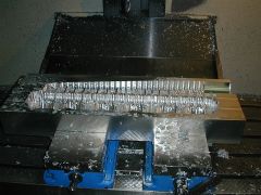
Sorry, I forgot to answer you on this one. The machine in the picture is a Fadal VMC 4020 with Fanuc controls. He does al of his programming in MasterCam 9 This machine is about a year old. They just got a new 6030 in the shop for larger projects. Total of about 5 vertical machines in the shop right now. So you want the file? Hmm I'll have to think about that one:icon42:
-
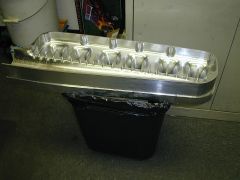
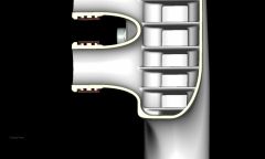
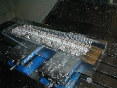
The first CNC pictures from before were of the roughing operation The final pass has been finished on the inside and it is ready for the back details. I had him spend a little extra time with a smaller step-over on the diverter section, but leave the entry into the runners a little more rough. I figured I would have to do some smoothing on the runner entries after welding on the Wiggins flanges anyway. He has already roughed out the inside of the front half. Should be only a couple more days to have it all finished machined. After machining I will pin it together for alignment, add a little tape to seal it off and bring it to be flow tested before welding it together for good. It seems like you guys like seeing the progress of the CNC work so I guess I'll keep posting pictures
-
-
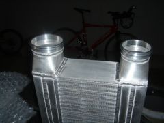
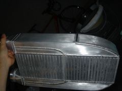
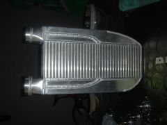
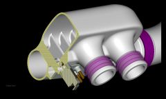
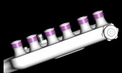
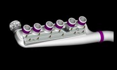
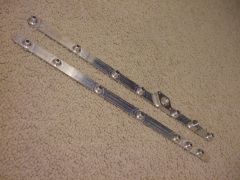
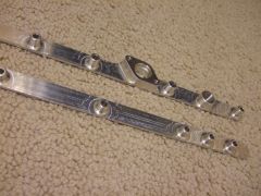
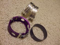
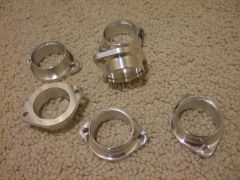
So, picked up some finished components from the CNC shop today. Here is what’s new- click on the picture for a bigger view The cover plates for the integrated vacuum and AIC rails. As you can see in the model I have designed rails in the back of the plenum. The cover plates will go over the slots and be welded close to form a rail. The top one is for the AIC solenoid and PCV valve. The bottom one will be for the MAP, blow off, fuel pressure, and boost gauge. Since I am using ITB I wanted a signal from each runner to collect into the rails. I also got the weld-on connectors for the Wiggins clamps. One side of the adapter will weld onto the plenum, and one side will weld to the ITB. The Wiggins clamp holds them together with no tools, so it will be easy to pull off the plenum to sync the ITB’s (thanks Tim for the idea) The bad news is the other day my friend at the machine shop called and said “hey your flanges are finished� What I said, and he sent me a picture. By mistake, he ran my old files of the bolt on adapters I was going to use to connect the plenum to the ITB's OOps. So he pulled up the correct files and finished the Wiggins adapters above. So, anybody need some beautifully machined adapters? They are standard Webber spacing and 45mm ID 6061. PM me and I can send you prints of them. 6pcs total. Since they are 1 off custom parts there not cheap, but I am just looking to help out my friend get some of his cost back. Jeff
-
-
-
-
-
-
-
-
-
Ya and 90% of it will be chips for the scrap man.
-
I think making a plastic model and testing it would be a great idea, as I do believe in taking the CFD results for what they are, just first results. For me aluminum is easier, faster, and cheaper than rapid prototyping. The CNC proto is being cut right now, check it
-
-