
Derek
-
Posts
1317 -
Joined
-
Last visited
-
Days Won
40
Content Type
Profiles
Forums
Blogs
Events
Gallery
Downloads
Store
Posts posted by Derek
-
-
I noticed something in one of the photos. You have what looks like carpet padding covering the dizzy hole. Now I saw your coilpack, so no need for a dizzy, but what is that material? Is it temporary?
DING DING DING we have a winner!
I was surprised no one said anything! It's a piece of terrazo colored corian solid surface material. I use it a lot for my prototyping. I wouldnt use it as a permanent solution but it's held up well for a few hundred miles! Keep your eyes pealed and you may see another piece as a fuel pump blockoff in the near future!
Too bad there isnt a prize though.
Derek
-
Hey Derek its looking amazing. Id have to say i would run your injector harness a little different also. You could hide it much better. I think i saw your relay board over by your battery in one of the pictures. You should try to run the harness under the manifold and back to the fire wall and into the hood latch brace and then to the relay board. Ive redone my injector harness this way since you've seen it and it looks so much cleaner. Obviously my relay board is under the drivers inspection lid but you get the idea. I really think you will like the look of it with out those wires there.
Thanks Jeff.
The issue isn't so much the injector harness as it is the vacuum lines for the vacuum log. They have to go across to the log that has yet to mounted on the fender well. Since I have those going across I might as well have the injector harness there as well. This routing tends to get everything out away from the heat faster than going to the fire wall. I made the harness long enough to go either way so I can still change it. In person it really doesn't look that obtrusive.
Derek
-
This may seem like a small thing, but, are you going to vid so we can all here the trupets resound with throttle cracking?
Please,,,,,,could you remove the fan?
It might kill the experiece too much.
I imagine if i don't do a video I'll be hunted down like the dog I am.
Fans,fans, fans.... all this talk about electric fans. Now I'm looking at ebay for a Taurus fan.... And searching Hybridz to see if it will work.
I agree the distinctive woosh will take away from the throttle sound.
Thanks Roger.Do you have any use for my first born, because I don't. But I would give just about any thing for one of those manifolds. WOW! Just beutiful. Keep it up Derek!Not interested in trades at this time but you can probably get enough for him on the black market or ebay though!
I guess you'll have to switch back to porn!Its almost sad to see it come to an end. This was my favorite project to fallow. What will I ever look at while I'm at work now.
I was thinking of the same thing earlier. As badly as I want this to be done I'm going to miss the design challenge.
Fortunately I've got lot's of other stuff lined up.
Hmm that valve cover is looking pretty plain.....
Derek
-
I reckon you could make some money selling prints of those photos. I particuarly like the Art Photo 2 (Looks like I picked up an old magazine) and Art Photos 1 is also really nice, would look cool with the engine in focus and the engine bay blured. Would look great as a A1 photo on my Garage wall. Also think it would look great as a black and white.
Now, onto the rest. I like the wires on the bottom, very clean looking. I don't like them coming out to the fender, but it isn't my design and I understand your motivation. (Your choice and so far you have been making great choices, so don't make me hinder you, it is just my preference). I love the glass beading on the valve cover. Very sexy, very sophisticated. (I have always like matt finished metal over super shiny metal). Were you able to do the Alodine finish your self (Just been reading up on it, sounds like an interesting finish compared to anodizing)?
All in all, great work derek. I don't know what else to say, "I'm Jealous".
EDIT:
Just looking back at your photos again. I didn't realise that you already had the injector wired hooked up! I didn't even see them the first 50 times I looked at your photos. That is super clean. Much better then my original idea. WOW!Thanks Garvice.
I really tried to make the vacuum log work on the firewall but it really wasn't cutting it for me. Although it fit it was so close to #6 stack that it really muddied up (warning art term ahead) the negative space. Now I have a clear definition between the stack and firewall.
Alodine is just a brush on hose off chemical treatment. I actually had some in stock under duponts 226S converter. The company who makes Alodine also has one that's clear.
Hi DaeronWal-mart sells small cans of cheapo spraypaint, IIRC its a primarily blue label. ~5 ounce can. There is a metallic silver paint that would match the coloration of the manifold and valve cover etc. that you might just be able to use on the brake/clutch hydraulic reservoir caps to make them match. I stumbled across it (I will look in Wally World next time I am there to see if I can find more specific info) and made a special note of how close the color was to "rough polished" aluminum (which is how *I* think of the look you achieved, however much bling the phrase may or may not imply.)Chrome is bling flat aluminum is not! I'd like to know what that paint is. Looking at how sad the manifold makes my engine compartment I'm going to have to do a little detailing.
I hear ya. I'm not posting this stuff to get petted by you guys anymore. I know your all behind me 100 percent and every one has been really supportive. How many times can you post "this thing is awsome"!I'm out of compliments. I can't think of anything that isn't repeating myself. Its CRAZY how many tiny little chores crop up here at what seems to be the "end game," but don't lose your patience and rush anything you may regret later. As much as we all await each update with bated breath, there's no pressure.I can't believe how long the details have taken. Although I've done a fair amount of prototype work I'm still surprised at how long the details have taken on this. But of course I'm usually billing some one by the hour so it has more of a warm fuzzy feeling.
I'm usually a 90 percenter when I do stuff like this. That's just my nature. I'm really trying to make this at least a 92.
Derek
Oh and look I finally have an avatar!
-
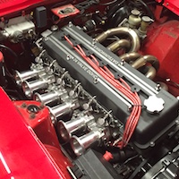
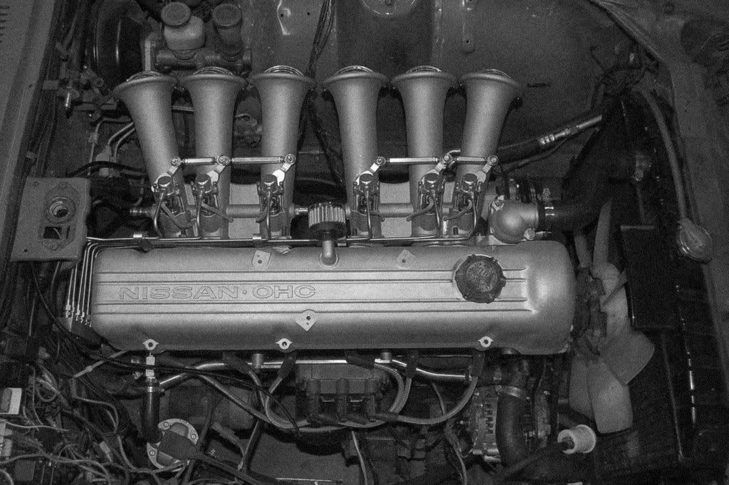
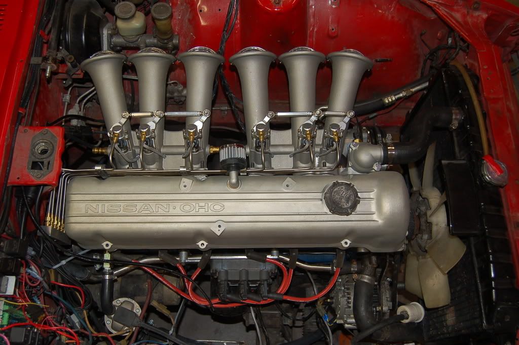
Made some good progress today!
As usual Tony was right on the money about the glass beading and Alodine. That's the same valve cover and water outlet that was in the previous shots. The finish is exactly what I was looking for. Clean but bling free. I really hope I can keep the wires below the manifold. It's such a clean look.
And of course I forgot to put the center link on the linkage for the shots.
I think the oil cap is going to need some attention!
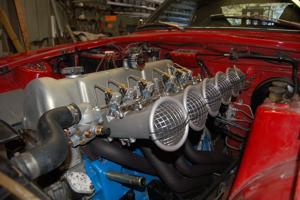
Art shot 1
Art shot 2
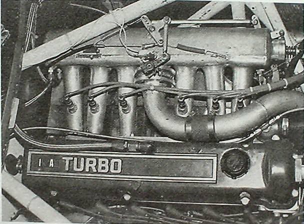
Which looks strikingly similar to this historic photo!
Now I didn't set out to copy Bob Sharps turbo manifold but it kind of worked out that way!
After I started designing my manifold I posted some early renderings on ClassicZ. Someone directed me to a post on the atlantic forum about a manifold they were trying to build. This was one of the pictures they had posted. I perused the thread and promptly forgot all about it. The other night I was revisiting some of the early posts and decided to have another look at the thread and saw that shot so figured I'd have a little fun.
I'm in no way comparing my manifold to Bob Sharp! But it's nice that it has the right feel for the era.
Here's the unedited shot which I really like.
I'm on a roll baby!!!
Oh and I will be fixing that rats nest of wires at the battery.
-
Looks great Derek.
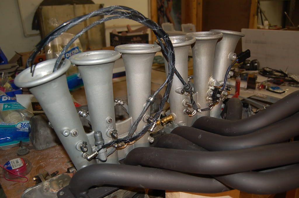
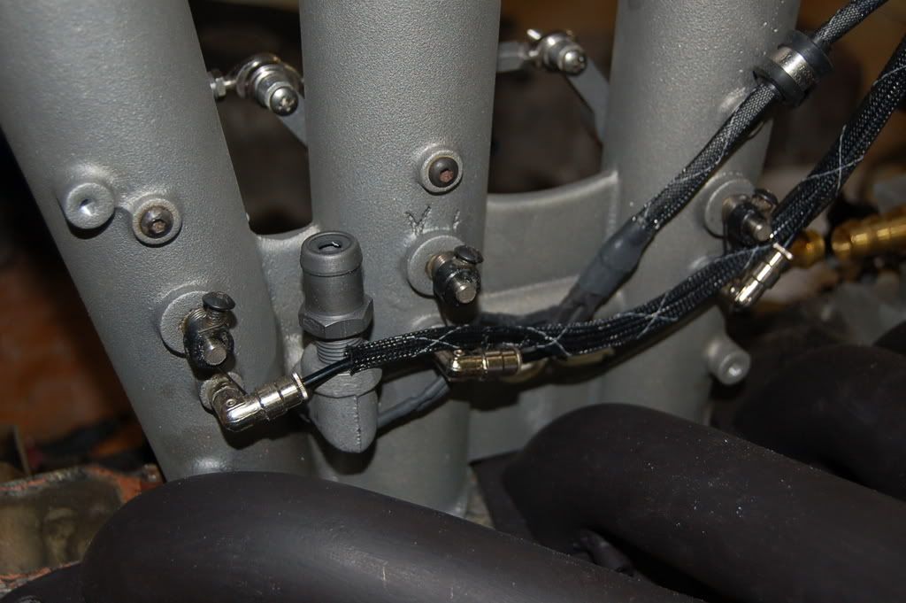
One issue I see is the wire sleeving. Unless you are running a heat shield, that stuff will melt so close to the header. Also, the TPS may not be able to take the heat. I would take Tony's advice and mount the TPS on the gas pedal or somewhere else in the linkage. Or, don't run one. You can use MAP base enrichment. I would eliminate all wires from under the manifold. Or you can get some of that high temp wire Sleeving:
Here's how I see it happening:
Whats that smell?
Why is it running rough?
Where is that smoke coming from?
I have 1/2" silica blanket that I use in my kilns. You can hold a torch against it and it barely get's hot on the other side. I plan on having that between the wires and the headers underneath the web of the manifold where you can't see it. The sleeving is a high temp version.
As soon as I get it running I'll be monitoring the heat situation. If it becomes a problem then I'll reach underneath cut the wires and run everything on top. I'm too far into it not to give it a try. It just looks so clean with everything underneath.
Derek
-
I think I just violated myself to your pictures.
I'll take that as a compliment!
-
It's been slow going but I'm plugging along. Everything seems to take forever. Or at least a lot longer than I figured!
Here's what I got finished.
Made thermo wells for EGT sensors and welded them in the header.
Stripped down the manifolds and welded on the new TPS bosses.
made a throttle cable bracket and welded it to the manifold.
Drill and tap for the PCV valve.
DAG 213 the throttle bores.
Assemble shafts and butterflies Dag them and bake at 350 for an hour.
Treat the manifolds with Alodine.
Run the vacuum syncro lines 2 or 3 times until I get something I like.
Run out of vacuum line.
Wire up injector clips.
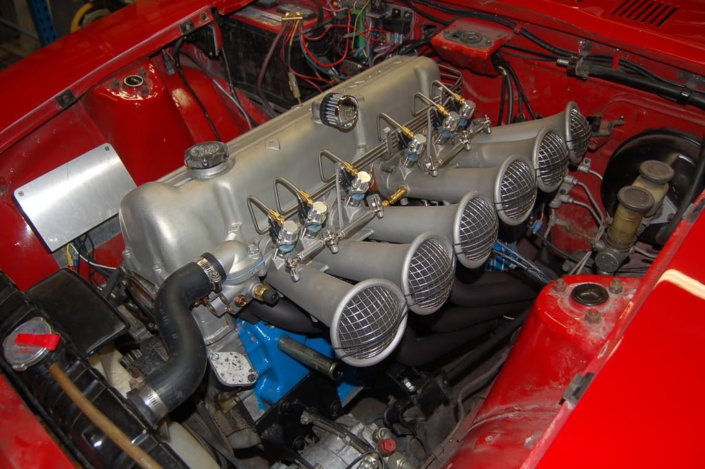
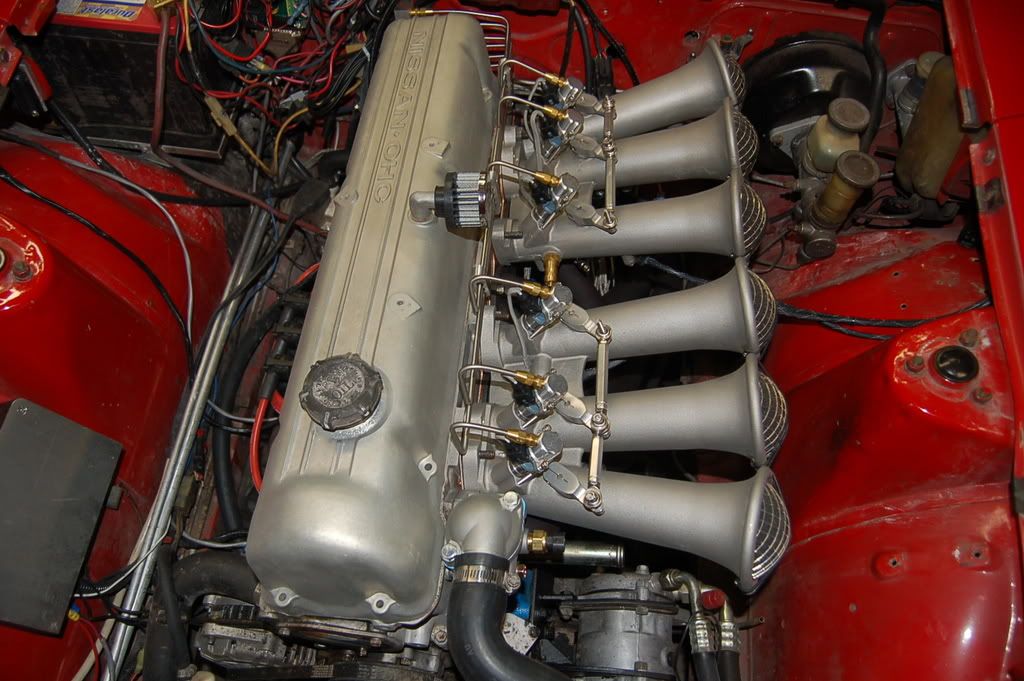
Here's some latest pics.
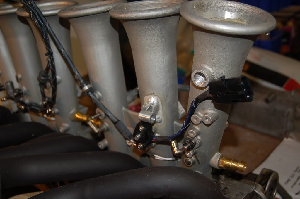
I've decided to mount the vacuum log on the fender well and run the lines and injection harness straight over. There just wasn't enough real estate on the fire wall for everything
PCV valve is working out well. I have to section the stock hose to fit but it won't be a big deal.
Here you can see the Throttle cable bracket and TPS. No vacuum lines yet on this side. The cable will run over to an arm that's on the empty shaft on #4
Next it's surge tank and fuel line installation.
Derek
-
I was talking about a ring that would fit on your dampener that had marks liek this, rather than 36...
See This dampener has only 12 notches out of it. I think the timing mark is about 35 degrees from the crankshaft key, but I would need to verify this. real similar to DJ's rear view pict.
phar
Phar you have me all confused. Are you doing this on purpose to distract me from my manifold:biggrin:
My setup is for the EDIS wheel only. What ignition system is that from?
Derek
-
You might think about using a new one because they are not all that expensive:
http://www.professional-products.com...ductNissan.php
I have this one on my race car. MSA sells it for $89. I think Damper Doctor charges close to $80 to rebuild one.
Well I need two pulleys so that's a non starter for me. You know we like our A/C in Florida! The rebuilding service is good to know though.
The whole assumption on my hub adapter is that the crank bolt is true and the hub adapter fits snugly on the crank bolt. The outer rim is concentric with the bolt hole. The laser cut 36-1 wheels are then bored to match the hub. The hub adapter has air gap all the way around it and only contacts the damper at the machined area where the crank bolt washer contacts.
Now having said all that If anyone wants to move towards using Pete's method PM me and I'll gladly refund their money. Fortunately I haven't spent it yet:biggrin:
But you better hurry I need some stuff for my manifold!
Derek
-
Just to prove I'm not stoned.
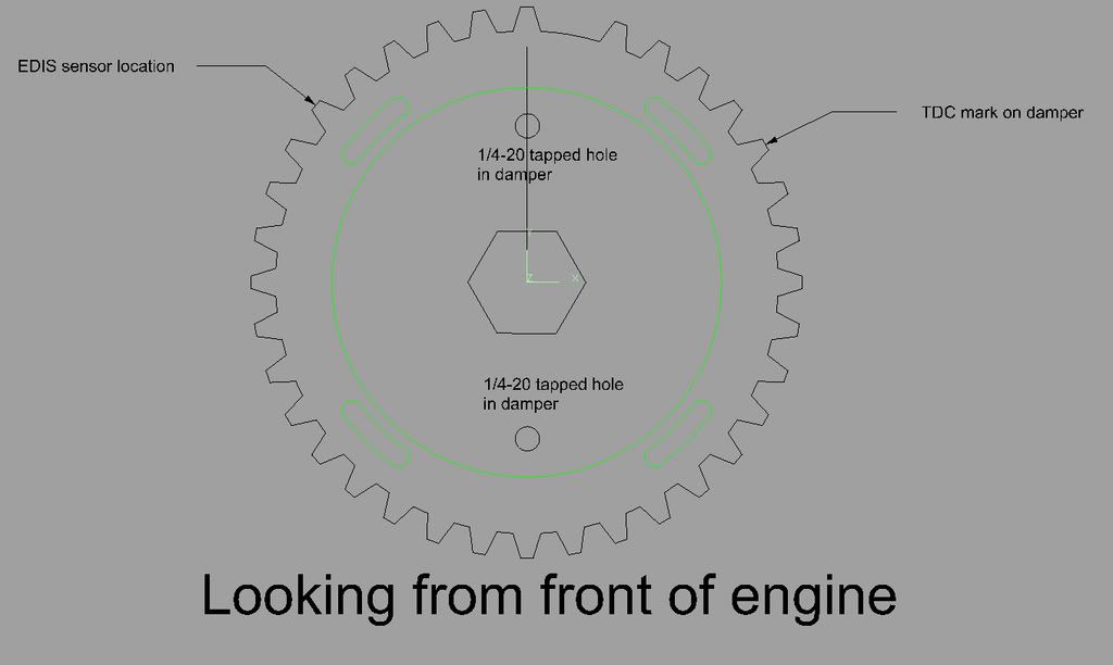
This is going to complicate things for some (all) of you. It appears my sensor holder bolts on to where your timing indicators currently mount. This is going to make your install a bit trickier. Your going to have to rig a timing indicator on the drivers side.
Here's the way it would work. Install hub adapter and 36-1 wheel. Set the timing indicator on 10 deg btdc. Make a timing pointer out of stiff wire (temporary) or out of sheet stock. Mount it in one of the holes that my indicator mounts to. Make a mark on the damper where the pointer is. This is now 10 deg. btdc (limp mode). Install sensor, align 36-1 wheel, check timing at new mark.
I'll add this to my install instructions with a little better detail.
If This is going to be too much hassle I can refund money.
Although making a wire indicator is a lot easier than making a sensor mount!
Derek
-
Hi Alex.
Now we're getting somewhere. Your damper is exactly the same as mine except for the timing mark. Mine is the mirror image of yours. My timing indicator badge is on the left side. Yours must be on the right side where the sensor mount is going to bolt. Am I correct on this?
Thanks
Derek
-
How about alternate notch patterns? How hard would it be to have you make one that could match up with alternate notch patterns, say to match a GM Pattern. the rest of the setup I'd be interrested in, but only if I could get this different pattern. though I might be able to just buy a Hesco Balancer if it would fit a L28 crank.. I'll have to pull mine off and see how similar the two are.
These are awesome btw.. but I'm sure I've said that before.
Phar
I'm not sure what your asking but the hub adapter will only fit the stock damper like this one.
I'm trying to find out the relationship between the 2) 1/4-20 puller bolts and the timing marks over the various hubs.
Ideally knowing the relationship between the keyway, timing mark and 1/4 20 bolts. would be great.
I'm trying to get this info so I can make these as close to a plug and play as I can get.
Thanks
Derek
-
Well aren't you living right!
Similar story.. Hurricane Andrew plows through Cutler Ridge. Get a call from a friend "can you get down there to my in laws with plywood gas etc and see what I can do. I round up 2 friends, and head down there with a sh!t load of stuff and do a bunch of emergency repairs. The dude has an awesome home machine shop as a hobby. months later the guy has a stroke. The wife calls me " come pick this stuff up I'm sure it will go to a good home"
I get the same sort of equipment as you and the exact I mean exact same band saw. That is an awesome machine and will serve you well for metal as well as wood.
Good luck (I think you already have some)
Derek
-
So there is a timing mark on the damper or is this the timing mark you see on the engine when the damper is installed?
I'll measure the threaded part of the bolt when I get home from work.
Alex
There's a tiny notch in the rim of the innermost pulley.
-
Dont have your car computer controling it yet?
No but I have it controlling my farting!
Right now with everything going on with the manifold that will be last on the list! It's still on the list though. The round knob panel looks good but the knobs are a little small and slippery and the symbols are really small to read. The lighting leaves something to be desired as well.
Derek
-
Here is a picture of my damper. For the record it came off a 1975 280Z.
Also, my crank bolt measures 47mm.
The washer is 8mm.
See attachments.
Thanks-Alex
Hi Alex
That looks like the damper on my car.
Where is the timing mark in relation to the 1/4-20 bolt holes. Also I need the length of the threaded area of the crank bolt.
Thanks
Derek
-
Stop farting so much and you won't need fresh air intake!
I have a/c tape over my fresh air intake and there are times when I wouldn't mind bringing in a little air.
I like that slide vent your using. I'm not super happy with the rotary knob unit I'm using.
Derek
-
I think it looks great. All except for that red and blue anodizing...So...Gauche.
Seriously it looks really tough. Nice work Pete.
Derek
-
Alright. I have the order placed with the laser cutter and according to him "it should probably maybe be done this week I'm pretty sure" Talk about being ambiguous!
I have may car ripped apart for the intake install and decided to pull the EDIS hub off of the damper. One thing that occurred to me is the 1/4-20 bolts that I had in there aren't really necessary for the function of the hub adapter. They are merely there as an index so that you can remove the hub after the car has been timed and reinstall it in the same place. Certainly the torque of the crank bolt will keep the hub from spinning. This allowed me to make a change on the hub and 36-1 wheel that I think is a real plus.
Here's a layout of what's going to happen
The design change is going from washers clamping the escort wheel in position to the laser cut wheel being slotted for adjustment. This is a much superior method of attachment. There really needs to be very little adjustment being as we're all using the same mounting point for the sensor.
This is how my setup is laid out. If the relationship between the timing mark on the damper and the 1/4-20 holes in the damper hub are all the same then this will greatly simplify the installation.
So if you guys can look at your dampers and see if they are drilled the same as mine or not and let me know it will help out a lot.
The bottom line is the 1/4-20 holes are not a make or break deal they just help with the ease of installation.
Also can you measure your crank bolt length. I'd like to supply a longer bolt with the hub to make up for the added thickness of adapter. Mine has a very thick washer and it looks like a 40mm is probably going to do the trick
Thanks
Derek
-
I will be in Florida starting tomorrow and won't be back for a week. Maybe either the 14th or 15th, I can spend an hour or two with you. I am far from an expert, but, maybe I can help.
Cool. The that means you can come over and help me with my install!! Florida's not that big of a state.
Derek
-
I'm putting together an instruction sheet for this installation. I'm running a little behind! One observation that I made is the 1/4 20 indexing bolts don't need to be in there. The torque of the crank bolt is more than enough to keep it from spinning. That's the recommendation I'll be making in the instructions after disassembling mine.
derek
-
It's hell being a pioneer. Wow a hacksaw to the pulley! Your a better man than I am. You did say you'd make it work though. I guess the offset on your damper is a little different. I'm glad you were able to make it work though.
Thanks again
Derek
-
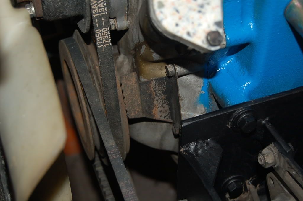
Will this give enough clearance when the engine rocks when it's running (loading / unloading the engine) ?
Nigel
I hope so! I've got about 1/2" clearance and I plan to run some sort of torque strap.
Derek that looks fantastic! Keep up the great work. I'll have to come down to see it in person.I'm dreaming about firing it up towards the end of next week. Maybe a good time for a club meeting!
Tony you have to wait longer to comment. That way at least some of this stuff will seem like my idea! Then again I could always say great minds.....Tie your engine down with a reaction strap or bar. The engine will move more than you think under power and braking and the last thing you want is your funnel forced hard against the hood causing deformation or worse yet cracking something off that ends up getting sucked in when the filter pops out. How much clearance is 'adequate'?Busting arse right now to try and get enough stuff ready to carve for next week so the machines will be working and I'll be working on the car. I'm thinking slow feed rates will be the order of the day! That way I'll have less interruptions.
Still don't have the thermocouples for the EGT yet so I have no idea what kind of well to machine.
Derek


Making my own EFI intake... The First Casting
in Nissan L6 Forum
Posted
Hi olie
I'm only using them for analysis. Since this is a prototype I want to be able to see how even they are.
Hi PharYes we did have a nice discussion on heat sheilds and I promptly discarded it as soon as I had the header on the mock up head. Here's the deal. I really want to design something that's as unobtrusive as possible. I really like the look of the headers through the manifold. In order to do this I have to run it so I can see what I'm dealing with thermally.
I have a insulation blanket that I'll be putting under the web to protect the wires and vacuum tubes. Hopefully this will be all I need.
The bung on 6 is the air temp sensor. That may get moved outside the manifold depending on how bad the heat soak is.
ThanksDaniel
Well I guess I'll stop looking for a taurus fan! Was it the shroud that hit compressor or the fan?
It will be a while before I do anything as I'm going to be burned out and a lot poorer by the time this is done!
Derek