Jump to content
HybridZ

Derek

Donating Members
  • Posts

    1326
  • Joined

  • Last visited

  • Days Won

    45

Everything posted by Derek

  1. So since I put in my CD009 I decided to do some checking into proper driveline angles. The transmission output shaft is right around 2.7 degrees which is good from what I read. but the pinion angle in it's factory position is 4.9. Anyone ever delved into this? I did some searches but I didn't see much about it. Is there a reason why Nissan put so much angle in there? I have a Ron Tyler style mount and I can top hang the diff and dial in the angle but before I do that I wanted to hear what you all had to say on it. Thanks Derek
  2. The 04-05 3.9 STI diff I believe is a Suretrac. No clutches. At least that is what mine is. From what I understand it's more like a Quaif unit.
  3. I know it's a long shot. Looking for a used input shaft for a CD009 6MT. The critical parts of the shaft are the pilot area and the front bearing. I need to make a QC test rig for the bell housing.
  4. I seriously don't think I would be doing this stuff if HybridZ didn't exist. It's really sad that people have taken to FB to find answers as opposed to going to forums. I read some stuff there and just shake my head at a lot of the answers. Back to the CD009. Working great. CD009 transmissions are notorious for gear rattle in neutral with the clutch out and mine is no different but other than that functionally it's fine. I think for my driving desires the 3.9 is a tad too much. The revs are a little high in 6th. I think a 3.54 would be a better choice. But the gear spread from 0-50 MPH is really a lot of fun in town. I think I'm going to put my stock rear and axles back in to get a feel for that and see how it goes.
  5. Actually I'm glad I have to cut the tunnel. It's my way of flipping off the series one purists:) I got a six speed and you don't na na na na naaa na.
  6. Thanks for all the kind words and what I think is a marriage proposal from Seattlejester. I love you too but you still have to pay full price for a KN20. Nice try though. Crap I missed a picture when I did the post. So I machine the bosses on the Nissan cover to the same level which keeps the bell housing parallel to the transmission. The three dowels keep the bell housing centered on the input shaft. Longer M8 bolts sandwich the whole rig together. If you look closely you can see the new boss for the clutch pivot so that it is on the correct side. The internal ribbing probably is over kill but I thought it looked cool. Every conversion system other than Hokes that I know of uses these bolts as the mounting point. From what I can tell I'm the first to use the existing cover. as part of the system. As part of the assembly procedure I recommend a dry fit with no clutch or pressure plate and the transmission in gear. Bolt the transmission to the motor with a pilot bearing installed. You should be able to turn the output shaft by hand if the input shaft is riding in the bearing properly. I'm confused by "just paid for the bell housing" I haven't sold any yet. Something else I missed was the fact you have to modify the tunnel just like every other CDXXX conversion. I'm putting the finishing touches on the installation instructions and I'll post the PDF here so people can get an idea of what is involved. Edit: Just talked to Chris at Godzilla. I'm no longer confused:) Well I'm still confused but that is my general state of mind.
  7. I know a lot of you follow this thread and I wanted to give you a heads up I'm coming out with a CD009 bell housing. I just posted a pretty detailed build thread over in Driveline. https://forums.hybridz.org/topic/131751-cd009-bellhousing-build-thread-warning-lots-o-pics/ There is a bonus video towards the end:) Thanks Derek
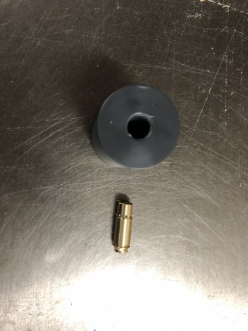
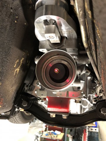
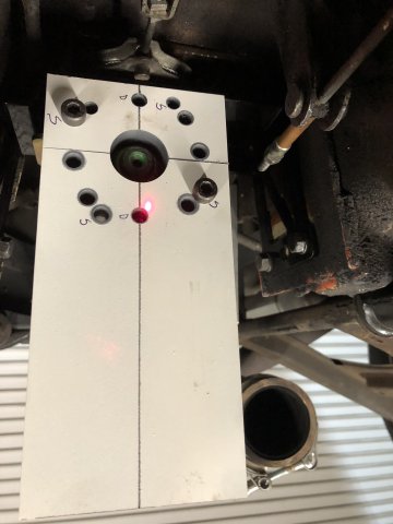
  8. Ever since I was a small boy I dreamed of having a 6 speed transmission in my Z car. Ok it was actually in 2014 when I heard that people were retrofitting the CD009 into various different vehicles and thought that would be awesome. At the time I was up to my ears in KN20 development and I put it aside immediately. Fast forward to a few months ago and I decided to finally bite off doing my own system. The Hoke system is a great piece of engineering but it wasn’t what I wanted. JWT offered a conversion plate but you needed to source a used bell housing and like the Hoke adapter required a special flywheel. The solution for me was always going to be a cast bell housing. My goals were to be able to use my existing clutch, pressure plate and flywheel. I contacted Chris at at Godzilla Raceworks too get his input on the feasibility of my approach. I know a lot about castings but my knowledge of what components play nice with other components is seriously lacking. Based on the info Chris provided I decided to move forward. Step one. Jump in with both feet by buying a brand new CD00A from Z1 Motorsports. Step two. Cut the bell housing off of a brand new transmission so there was no turning back. The first thing I needed to determine was can I get 100% spline engagement on the clutch disk. I setup a block, crank and flywheel on the bench. I removed the pilot bearing. I then slid the transmission into the crank until the pilot shaft bottomed out. I pulled it back 6MM and made a reference mark on the bench. Visually the pilot shaft looked like it would play nice with the pilot bearing so I moved on to the next step. Check spline engagement. I bolted an old PP and disk on and slid the transmission back into place. I had over 100% engagement and it looked like some version of the longer release collar would bridge the gap. So now that I was confident the math would work I had to work out how I was going to machine the casting. The big problem for me is my CNC mills are converted Knee mills and they don’t have a lot of Y axis travel. I also don’t like doing uber precision work in a production environment. I decided early on that I was going to leverage the existing front cover to be the “glue” between the transmission and my bell housing. My plan was to sandwich the front cover between the bell housing and transmission. After confirming that I had a decent machining strategy it was time to collect data. I scanned an old 5 speed case I had. This is what I refer to as a dirty scan. It’s only for me to design around. I import the mesh into my solid modeler and it becomes a reference for the features I want to add. All of the critical measurements are done with a touch probe in the mill or conventional calipers and micrometers. First step was to align the mesh with the bell housing holes I acquired with the touch probe. I also pulled the input bearing hole from the case when I got the bolt pattern. I then then positioned the scan and the probe data I made of the CD009 cover centering the input with the input from the case. And then I push a couple of keys and suddenly like magic a bell housing casting model appears. Ok there is a lot more to it than that but you get the gist. Next I had to design the machining fixtures. All of the important stuff is done in the first setup. This ensures the input shaft of the transmission lines up with the pilot bearing in the crank. Pattern time. Without getting into a ton of detail here is the finished tooling just before I shipped it to the foundry. So while I waited for the castings I worked on all of the fixturing. By using the existing front cover I was able to save a ton of precision machining. But the cover has to be positioned properly. I accomplished this by making a fixture that indexed the cover on the input bearing. I then bring all of the bolt face bosses to the same level and then ream 3 of the bolt holes to accept a 10mm hollow dowel. Here is the finished cover with the dowels installed. So I guess I was in a hurry on the machining since I didn’t get any process shots. Here is a shot of the first test after machining the engine flange. This is testing the cover fit. This is before the clutch lever and slave work. And the finished product. I designed the cross member to be as versatile and adjustable as I could. I also decided to share the load between the floor/frame and tunnel. On most of our cars the tunnel is probably one of the most unmolested rust free parts of the car. It uses the crossmember from a 72 and up and an Energy Suspension transmission mount. Both ears are adjustable up and down and the ears are slotted so the cross member is adjustable side to side. You can remove the transmission just by removing the ears. The floor/tunnel bars stay in place. Here is a slightly fuzzy shot from underneath. And the finished product. What’s next? Now that I have a running car I’m finishing off a second bell housing and cross member and sending it out to Chris at Godzilla. He is going to test fit it in a 280Z and check the fit of the cross member as well as the clearance on some headers. Godzilla Raceworks is going to be a dealer for these and he took care of having the drive shaft made. As soon as we verify the fit on his test vehicle I’m going to go into production. I’m not taking pre orders but if you want to be on the list of pioneers you can contact me or Chris at Godzilla. When the bell housings are done you will have the first option to purchase. Pricing: Bell housing. $900.00 Crossmember. $295.00 Labor charge for modifying front cover. $75.00 You must supply either a brand new cover or brand new take off as a core. No used covers will be accepted. So far I’m really liking the gear spread on the 6 speed. I currently have a Subaru 3.9. I’m going to put the stock 3.364 diff back in to see if it brings the revs down at 75mph and see how it effects the first and second gear feel. For me that is the most important thing. Thanks Derek
  9. As in Ohm readings? No not really. Since I used the calibration feature of the MeterMatch as opposed to the pre configured method there isn't any way to know for sure.
  10. So I finally had the right combination of events to where I ended up with 1/4 tank and the time to drain and measure. I used a 5 gallon gas jug and it was so close to 4 gallons that I'm calling it a winner. The needle does start to swing a bit down around 1/4 tank and I did have one scare. I was about 30 min from the shop and I was hovering around 1/4. I pulled up to a light that was on a bit of an incline and the needle bounced down to E for long enough for me to convince myself I was running out of fuel. I wasn't but without knowing for sure I threw in a few gallons. It is way better than it was before and I'll probably run it down to 1/8th and see where I'm at. As long as I can count on it to between 1/4 and 1/8th then I'm golden since that is usually as low as I run it.
  11. Yes but the owner of Technoversion drives a 240 so there is that to consider:) Went for about a 45 min drive today. Gage went down as expected and was rock steady the whole time. I do want to reiterate that I change my sender wire and installed the MM at the same time. I would do that first since old wire and connections are not a great combo for dependable ohm eadings
  12. Yes. I did the coarse setting with the MM and then refined it with the gauge. Yes. The needle moved slowly which gave me some hope. I then installed the sender and added gas at a known amount and checked the gauge to verify. It was very accurate without any other tweaking but I wanted to get it dialed in at the 3/4 mark since that is probably pretty close to the point where the tank narrows. The drive home went well and the needle was more stable than it has ever been. The real proof will be when it get's down a little past half. that is when I really noticed the massive swings. The needle would literally go from half a tank to empty.
  13. I just posted this in Electrical but here it is as well. Speedhut fuel gauge and MeterMatch Like a lot of others I’ve had issues with the Speedhut fuel gauge playing nicely with the stock fuel tank sender. I would get wild swings and was never really sure how much fuel I had. After some discussions on the Speedhut group buy thread I decided to get a MeterMatch from Technoversions. It basically takes the ohm readings from the sender and converts them to a more stable range for the gauge. So here is how I attacked this. I tried to install it without pulling the sender and it was just not working. And during the course of this I was getting some erroneous readings from the sender. So I drained the tank all the way and pulled the sender. I brought the sender into the car so I could manually move it to see what was going on. I set the fuel gauge back to default of 240 empty and 33 full. I then used the MeterMatch to set full and empty calibration. To calibrate you used up and down buttons to move the gauge needle and then save it when you get it where you want it. I had a really hard time since a single button push moved the needle almost a 1/4 tank. I ended up getting it close with MM and then doing a final calibration with the gauge. This worked really well. I reinstalled the sending unit and rewired it with a new good ground and a dedicated sender wire straight to the MM. I have a 16 gal tank. I put in 2 gallons and the meter read 1/8 and was stable. So far so good. I put in two more and it was a little above 1/4. Still good but I wanted to try the lower mid point calibration. As before the button presses moved the needle a ton. But I noticed the needle wasn’t stopping at the same place. I found I could walk the needle around by different combinations. I went to the gas station and put in four more gallons and the gauge read 1/2. Four more and I was a little above 3/4. Went for a drive and the needle was really steady compared to what I had before. Let’s face it a lever arm sender is going to have a lot of movement and if the gauge isn’t designed for that sender then it’s only going to be so good. So I got back to the shop and contacted Brian at Technoversions with questions about the up down calibration. Here is his reply: With regard to the MeterMatch, what you are seeing with the up/down resolution is on purpose. Most gauges use a fair amount of current, so if we made the buttons work at full resolution, you could be pressing one of the up/down buttons a thousand times to go from end to end. So we make the buttons move the amount in larger increments. But to make the points in-between accessible, we make the increments between up and down slightly different, so that all values can be selected. This is hardly noticeable on most gauges, but on some electronic gauges, such as the one you have, much less current is necessary so you are working within a small range of values, so the resolution appears to be much coarser. But you should be able to get there. So you can hit a specific target with the right combo but I will tell you it is a challenge. You can get the needle where you want it and after you take it out of program mode it changes. I set the upper mid point calibration the best I could considering the heat index in Florida right now and may revisit it in the future. From 3/4 tank and up I don’t care if it is accurate and truth be told as long as I can count on 1/4 tank being stable and accurate I’ll be happy. So to sum up. I would run a separate dedicated ground and signal wire first since in all reality that may have been the bulk of my issues. I already had the MM so I used it. If That doesn’t work for you then: Purchase MM from Technoversions Set the fuel gauge to default ohms since that is where it was designed to work. Use the MM calibration to get the needle to full and empty as best you can. I wouldn’t get too crazy with the button pushes since you are going to set the final calibration with the gauge. Recalibrate the Speedhut fuel gauge. Install the sender and use known amounts of fuel to check calibration. I plan on draining the tank when it reads 1/4 and if I have 4 gallons then I’m golden. I’ll update this thread after I drive it a bit as well.
  14. Like a lot of others I’ve had issues with the Speedhut fuel gauge playing nicely with the stock fuel tank sender. I would get wild swings and was never really sure how much fuel I had. After some discussions on the Speedhut group buy thread I decided to get a MeterMatch from Technoversions. It basically takes the ohm readings from the sender and converts them to a more stable range for the gauge. So here is how I attacked this. I tried to install it without pulling the sender and it was just not working. And during the course of this I was getting some erroneous readings from the sender. So I drained the tank all the way and pulled the sender. I brought the sender into the car so I could manually move it to see what was going on. I set the fuel gauge back to default of 240 empty and 33 full. I then used the MeterMatch to set full and empty calibration. To calibrate you used up and down buttons to move the gauge needle and then save it when you get it where you want it. I had a really hard time since a single button push moved the needle almost a 1/4 tank. I ended up getting it close with MM and then doing a final calibration with the gauge. This worked really well. I reinstalled the sending unit and rewired it with a new good ground and a dedicated sender wire straight to the MM. I have a 16 gal tank. I put in 2 gallons and the meter read 1/8 and was stable. So far so good. I put in two more and it was a little above 1/4. Still good but I wanted to try the lower mid point calibration. As before the button presses moved the needle a ton. But I noticed the needle wasn’t stopping at the same place. I found I could walk the needle around by different combinations. I went to the gas station and put in four more gallons and the gauge read 1/2. Four more and I was a little above 3/4. Went for a drive and the needle was really steady compared to what I had before. Let’s face it a lever arm sender is going to have a lot of movement and if the gauge isn’t designed for that sender then it’s only going to be so good. So I got back to the shop and contacted Brian at Technoversions with questions about the up down calibration. Here is his reply: With regard to the MeterMatch, what you are seeing with the up/down resolution is on purpose. Most gauges use a fair amount of current, so if we made the buttons work at full resolution, you could be pressing one of the up/down buttons a thousand times to go from end to end. So we make the buttons move the amount in larger increments. But to make the points in-between accessible, we make the increments between up and down slightly different, so that all values can be selected. This is hardly noticeable on most gauges, but on some electronic gauges, such as the one you have, much less current is necessary so you are working within a small range of values, so the resolution appears to be much coarser. But you should be able to get there. So you can hit a specific target with the right combo but I will tell you it is a challenge. You can get the needle where you want it and after you take it out of program mode it changes. I set the upper mid point calibration the best I could considering the heat index in Florida right now and may revisit it in the future. From 3/4 tank and up I don’t care if it is accurate and truth be told as long as I can count on 1/4 tank being stable and accurate I’ll be happy. So to sum up. I would run a separate dedicated ground and signal wire first since in all reality that may have been the bulk of my issues. I already had the MM so I used it. If That doesn’t work for you then: Purchase MM from Technoversions Set the fuel gauge to default ohms since that is where it was designed to work. Use the MM calibration to get the needle to full and empty as best you can. I wouldn’t get too crazy with the button pushes since you are going to set the final calibration with the gauge. Recalibrate the Speedhut fuel gauge. Install the sender and use known amounts of fuel to check calibration. I plan on draining the tank when it reads 1/4 and if I have 4 gallons then I’m golden. I’ll update this thread after I drive it a bit as well.
  15. I just pulled trigger on the Techoversions unit. I will report back as to the results.
  16. This part from the instructions got my attention. That is exactly the issue I'm having. The slightest movement on the sender makes the gauge swing. This is also interesting as well. I have a lot of electrical items and I'm sure the voltage swings quite a bit depending on conditions. Not sure if this bothers Speed Hut gauges.
  17. Just a heads up. Techo versions the company that offers the Ron Tyler mount also offers/makes the meter match. The more I read about it the more I think that is probably what we are looking for.
  18. I did as well so I put in a brand new sender. I think it made it worse:) That would be great. I'm going to check the connections to the sender this morning and make sure nothing is loose.
  19. Just got back from a drive and the gauge was swinging form 3/4 to empty at what seemed to be random intervals. I got nervous and fueled up and it only took 4 gallons. I read somewhere that the the voltage to the gauge can effect the reading but not sure if that is valid. Any thoughts on this unit? https://www.tanksinc.com/index.cfm/page/ptype=product/product_id=473/category_id=167/mode=prod/prd473.htm Pricy but if it will solve my problems then I'm willing to go that direction. They also have this: https://www.tanksinc.com/index.cfm/page/ptype=product/product_id=748/category_id=167/mode=prod/prd748.htm That is probably a very accurate assessment
  20. I think when it comes to safety and when using a mis mash of parts documentation is important. If they are two ways for an item to be mounted but only one works then that requires documentation.
  21. After the hassle I had with the kit from Zcar depot's Ebrake function I wouldn't buy it without detailed instructions and pictures of it installed. So much of this stuff is not much more than a collection of parts that require a lot more work on the users end than they let on to. To sell a brake kit without detailed downloadable instructions is almost criminal in my mind.
  22. The gauges themselves are great as far as I'm concerned and I would search specifically for this ohm problem with any other set you look at.
  23. +1 for this. I'm currently in therapy because of range anxiety. Looks like I have half a tank, great, looks down again, Empty???
  24. Great job. You are right it looks like it was originally that way.
  25. Mine is the one in the speedo. There is an old post by KTM where he had the same issues and I'm almost positive that is the stand alone gauge.
×
×
  • Create New...