Derek
-
Posts
1344 -
Joined
-
Last visited
-
Days Won
53
Content Type
Profiles
Forums
Blogs
Events
Gallery
Downloads
Store
Everything posted by Derek
-

Twin cam head for the L6 from Derek at Datsunworks
Derek replied to Derek's topic in Nissan L6 Forum
No Actually my specialty is pattern making and casting design sprinkled with a little machining and a lot of dreaming. I leave the rest of that stuff to people who are far more knowledgable than me. Yea that combo has more than one person, me included, to rethink their builds. My thinking at this point is basically a Rebello style 3.2 build with offset ground LD crank, rods, and pistons. Bore the block to a safe number based on sonic testing and call it a day. For years people have been saying that the majority of the L6 power comes from the head and this is really proving it to be true. The DOHC configuration moves a ton of air without a ton of lift compared to the stock single cam heads. -
Twin cam head for the L6 from Derek at Datsunworks
Derek replied to Derek's topic in Nissan L6 Forum
Yes. It's a 3.1 ish. The OS was a 3.3. Not sure why Rob hasn't been more vocal about the results but I'm sure he has his reasons. Let's just say the owner is happy with the KN20. Hopefully ZCG will publicly post some numbers soon as they are impressive. -
Twin cam head for the L6 from Derek at Datsunworks
Derek replied to Derek's topic in Nissan L6 Forum
I have no plans but if someone wanted to they can add sensors to the back of the valve cover to monitor the cams. I have a single sensor on the intake for the VVT on my car. It's the guts from the existing tensioner that comes in the KA24 timing chain kit. The spring in most cases provides more tension pressure than the oil pressure against the piston can. Max potential at 70 PSI is like 17 pounds of force. The springs I measured from tensioners come in at between 13-16 ish. The oil is in there for damping and lubrication as much as the pressure. The check valve I'm guessing is there to help with that as well as cold starts and rattling. What Leon said. They are both great shops but like all artisans they have their proclivities. Thanks Leon. The only footage other than my car and 005 is the dyno pull that ZCC did. https://www.instagram.com/p/CMKqD5BHwrr/ -
Twin cam head for the L6 from Derek at Datsunworks
Derek replied to Derek's topic in Nissan L6 Forum
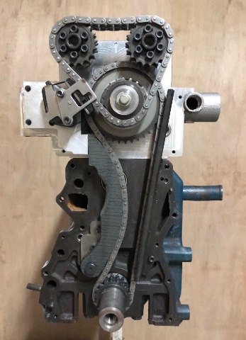
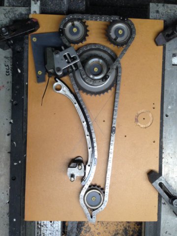
Story time. As many of you who have followed along for a while know the timing chain arrangement has been my White Whale since the beginning. I knew I wanted to use the KA24 timing chain setup and for the most part I was able to make that work. The problem was there just wasn’t enough room to fit the pivoting slack side guide and have it pivot at the bottom like it’s supposed to. The compromise was to pivot it at the top, use a custom guide and use the bottom tensioner in the stock L6 position. This worked but the custom guide had to be a little thin in one area to clear the lower timing cover. Now here comes a lesson for all you aspiring engineers out there and how solutions to complex problems can be incredibly simple. I was speaking to Brian at Rebello after he finished the KN20 build they did for Z Car Garage. This was the first build they did for a sub 3.2L and they decided to use my system as opposed to the more complex system they designed for for the 3.5 motors. We were discussing the lack of room on the slack side for the top pivoting guide and he mentioned that the KA24 heads have the idler gear pushed towards the tension side more than I had mine. I agreed this was worth looking into and set about manipulating the 3D model to see what I could make happen. I found I could pick up about 19mm by shoving the idler gear over. On the face of it a very simple solution to increasing the thickness of the pivoting guide. Problem solved. But wait it get’s better. As I was sitting at my work station shoving various 3D components around to see what was workable I realized a fair amount of room opened up on the top and there may be room to squeeze a tensioner up there and have the bottom pivot guide I always wanted. I contacted Tioga who is my go to person for all things OEM and he got me info on the various available external tensioners that could possibly work. The problem was they were all too big to fit. Then the epiphany. Why not design my own tensioner that will fit inside the existing available envelope. Booooooommmm. The hardest part was that I absolutely wanted it to retrofit to the existing heads I already had out there. It was apparent that this would work and fortunately I had a head still here so I set about with my tried and true mockup process. A little CAD/CAM add a little old school analog, bring the analog back to digital, rinse and repeat. I ended up with this mockup. The letter T represents where the tensioner piston is. And here is the final product. The adjustable cam sprockets are from Tomei FYI and are really well made. The slack side guide is much more robust and the front lower timing cover fits without any modifications. The stock L6 tension side guide fits with some minor slotting and cutting. The chain angles and flow look great so I’m super happy with the outcome. The tensioner is also the mount for the upper tensioner. The slack side tensioner uses the piston, spring, and check valve from a KA24 tensioner. The body is 6061 aluminum with a 4130 DOM (drawn over mandrel) honed sleeve inserted as the cylinder. The front of the head has scuppers to drain the oil from the valley and the new tension block blocked the right one. I had to machine a drain into it and decided to include a dribble hole to help oil the lower chain. Probably useless and the KA24 upper tensioner pukes so much oil that I doubt the lower chain will ever run dry but I felt like putting it in. It feels really good finally making this work and short of any minor changes this is going to be the go to chain system for anyone running a single row lower chain. PS. This is one of the original mockup picture of the timing chains and no one mentioned "You know the KA24 idler is pushed over towards the tension side more" So ultimately I'm blaming you guys for missing that.
-
My understanding of the polygon effect was it induced instability (whip) as it exited the sprocket. The smaller the sprocket the more instability. So you have a whip in the chain at the bottom coming up all the time. Couple that with the dynamics induced during overrun conditions and you can see controlling a timing chain can be tough. Now change the dynamics again with different lifts and lobe offsets and chain wear and breakage comes into play. The tension system is as much a dampening system as it is anything else. I'm sounding doom and gloom but I think when people make changes to the timing chain system they should be aware of what they are dealing with. There are ton's of people running those twin idlers without a single issue so there's that. Plus it's not like anyone is going to be putting 100K miles on these cars anymore.
-
During the design phase on the KN20 I did a lot of research into timing chain designs. I did some calculating on what kind of pressures the tensioners were delivering. In a perfect world a .567' (14.5mm) diameter rodless hydraulic cylinder will deliver just over 17 pounds of force at 70 psi. I measured a few springs from tensioners and they were all in the 14-15 pound range in their operating position. So there really isn't a lot of force provided. Also I think tensioners for all practical purposes are spring driven and oil oil dampened since anything under 70 psi the spring is delivering more force than the oil pressure. Chain sprockets are a polygon and suffer from what's called polygon effect. When the chain exits a sprocket it induces whip. The smaller the sprocket diameter the bigger the effect. I think that is why bottom pivoting slack side guides became the norm. Much more surface area to control the polygon effect as well as a faster response time when the engine goes into overrun since that happens at the top of the guide where the tensioner is.
-
Twin cam head for the L6 from Derek at Datsunworks
Derek replied to Derek's topic in Nissan L6 Forum
Well a capable shop could have done it before if they wanted to take the time to do it as a bespoke head but yes this opens up the possibilities for CNC porting. -
Twin cam head for the L6 from Derek at Datsunworks
Derek replied to Derek's topic in Nissan L6 Forum
Well the HIP shrinkage is a direct result of the porosity in the metal. I suppose a foundry with more sophisticated process control could manage micro porosity better but that is leagues above the people I work with. The last batch of four heads we did were poured one right after the other as fast as we could and they all shrank at different rates. At this point it's not a problem I need to solve since I've made the transition to chills. Thanks anyway though. All the machining is done with CNC controlled machines. Although they are converted manual machines they get the job done. -
Twin cam head for the L6 from Derek at Datsunworks
Derek replied to Derek's topic in Nissan L6 Forum
The casting shrinkage during solidification is pretty predictable and repeatable. The shrinkage from the HIP process on the other hand was really tough to predict. -
Twin cam head for the L6 from Derek at Datsunworks
Derek replied to Derek's topic in Nissan L6 Forum
It's A356 heat treated to T6. -
Twin cam head for the L6 from Derek at Datsunworks
Derek replied to Derek's topic in Nissan L6 Forum
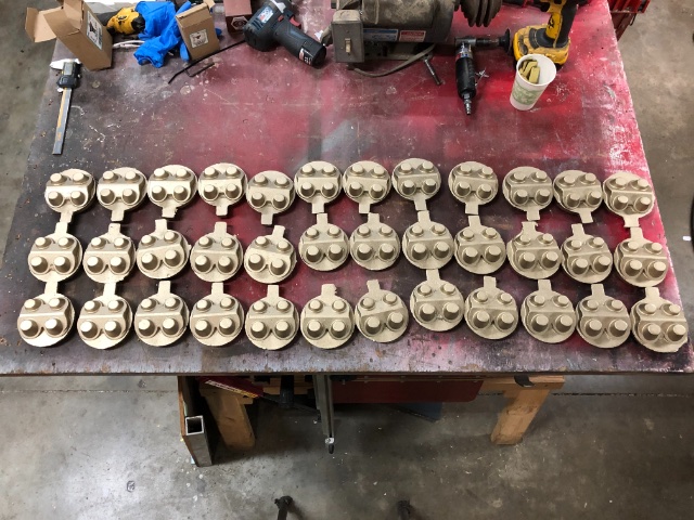
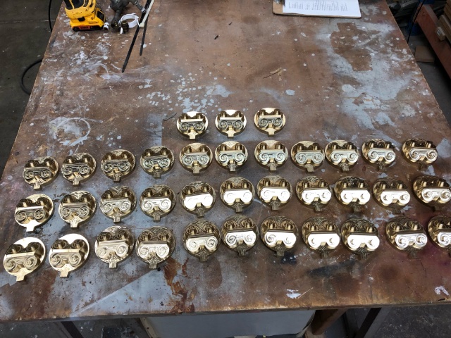
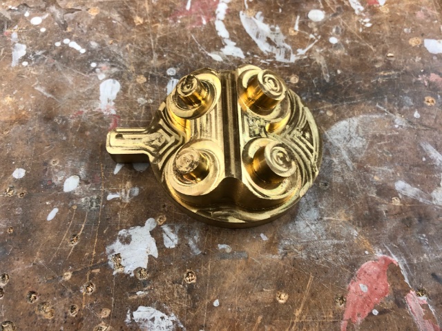
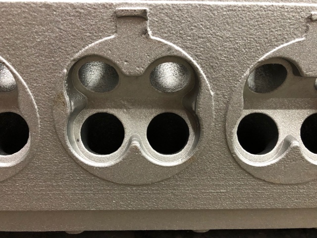
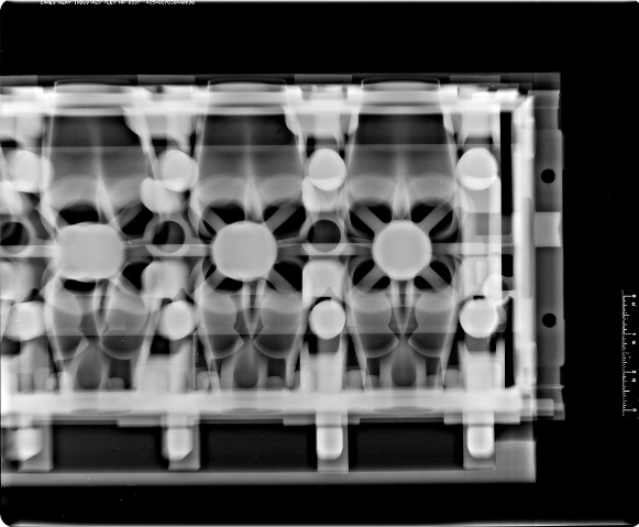
Update time. So I wanted to update the thread to reflect a change I made to the casting process. As some of you may remember I started using a method of conditioning the castings called Hot Isostatic Pressing. The HIP process heats the head to like 700 degrees F in a pressure chamber and then Argon gas is pumped in at around 25K PSI. This crushes the micro porosity in the casting and makes for a much denser part. Unfortunately after two rounds of heads I have come to the conclusion that even the slightest difference in porosity can lead to pretty big differences in the size of the heads. It was making the machining much more difficult than it needed to be. The reason I went this way in the first place was I wanted to make sure the combustion chambers were dense. So I opted to go with a more traditional method of metal control which is using something called a "chill" Chills are usually metal and their function is to cool the aluminum in a specific area. I have been using an external steel chill in the front of the head since V1 to control the metal shrinkage since it is so thick there. Chilling the metal makes for better quality. Combustion chamber chills are nothing new I just wanted to avoid them if I could. Well I couldn't I chose to make them from bronze for a number of reasons. Thermally they will do what I wanted and manufacturing was a lot simpler than steel. I made a pattern of the rough shape I wanted and had them cast in bronze. I need one for each chamber but they are reusable as long as they don't get damaged. And like magic they are machined. The shape of the chill is the same as the combustion chamber shape that I have been using all along. Using chills required a redesign of the ports, water jacket and the external parts of the mold since it could no longer be 3D printed as a unit. It became a little more like a traditional mold in that we now have to hand set the port cores. The round buttons on top of the chill is what locates the 3D sand cores. The ends are supported and located with rods that pass through the mold. This provides for a very accurate placement of the core. We poured a test head and everything went great. No visible defects. Since it was such a large change I had the head X-rayed to make sure there wasn't any defects. Everything looked good. Hopefully this is the last big change to the head casting procedure. The HIP process was really cool but ultimately it induced too much uncertainty in the machining and it really ran my anxiety levels up.
-
Don't you find it strange the only post from this person on this forum is digging up a post that has been dead since 2016? I have a Braille B2618 in my Z that I daily since Feb. 2019 with zero issues. I will say one thing. They absolutely hate parasitic draw. If I'm not going to drive it for a couple of days I put a tender on it. Also if you break down on the side of the road you won't get too many "ok try it again" out of it. Derek
-
Man I wish I had the time and energy to do big projects like this. Looks like a really fun project.
-
That looks really good. Nice work.
-
Has anybody have problems dealing with ZCAR DEPOT?
Derek replied to toolman's topic in Non Tech Board
My only complaint with Zcar Depot is the parts that they make or have made for them don't ever fit properly. I stopped ordering that kind of stuff but I find their service as far as filling orders and getting them out promptly pretty darn good. -
What size injectors are you going to use on the 3.1?
-
Using 5/8 bolt in place of spindle pin
Derek replied to fusion's topic in Brakes, Wheels, Suspension and Chassis
Oh that's different:) Carry on. -
Using 5/8 bolt in place of spindle pin
Derek replied to fusion's topic in Brakes, Wheels, Suspension and Chassis
Since the 5/8" all thread is smaller than the original pin over time you will develop what is called fretting. The fretting is a type of wear and can create a rusty looking finish. I personally would stay away from all thread and just spring for the pins. -
curious to know what are the best L Series Transmission options now?
Derek replied to primaz's topic in Drivetrain
So to clarify things a bit. I produce the bell housings and sell them to Godzilla. They sell them individually or as part of a kit. Godzilla can offer a level of support that I can't and I have had nothing but excellent dealings with them on other things. After I catch up with demand I will start selling bell housings off the shelf but that most likely will be the extent. Godzilla is taking pre orders and the last I heard they had 8 openings left. The patterns are at the foundry waiting for an opening but the holidays are screwing up the schedule. Godzilla charges the same as I will be. I have no real schedule for the TL70. I have to finish the CD009 castings I currently have on order then I can jump on the new one. Probably 4 months minimum before I have a working solution and bell housings to sell. Hope that clears things up. Derek -
curious to know what are the best L Series Transmission options now?
Derek replied to primaz's topic in Drivetrain
I'm no transmission expert by any means but I do play one on TV. As NewZed said the OP needs to define his goals. There are 4 options that I know of that would be considered better than stock. The 240sx 5 speed with modified bell housing. The problem with this conversion is replacement parts are getting harder and harder to come by. There have been some tolerance issues with some of the aftermarket parts as well. I hated the gear ratio spread. One of the T5 options or a variant of them. I don't have any opinion on those other than they are fairly noisy and they only go to five:) CD00A 6 speed with one of my conversion bell housings. The CD is a proven transmission and will take a ton of power. It is available brand new from Nissan for a very reasonable price. The biggest downside is you have to cut the existing mounts from the tunnel and for a lot of people that is a no-go. There also can be significant input shaft clatter with the clutch out and in neutral. The biggest upside for me is it goes to 6 and Madkaw's only goes to 5. Seriously though for me it was all about the gear spread. 5th is 1;1. Think about it this way. My old knees would rather climb a ladder in 6 steps vs 5. The gear spread just seems to work really well for my style of street driving which is 0-50 as fast as I can. With the 4 speed I felt like I had to kill it in every gear to get any kind of acceleration. Now it is a much smoother proposition. The Aisin TL70 6 speed which I'm currently developing a conversion bell housing for. It can't take the power that the CD00A can but it will fit the tunnel without any modifications. It is very plentiful on the used market since BRZ owners like to wreck their cars a lot as well as brand new from Subaru. The gear ratios are pretty close to the CD00A. There is no definitive data on how much power it will take but from what I have read and some data from one of Godzillas customers I felt it could handle 375 to the wheels. I may be a little optimistic on that number but so much of the stress on a drivetrain comes from driving style and tire grip. I personally feel this transmission conversion will be a good choice for a lot of normally aspirated cars. I'll know a lot more when I get the first one in my car to play with. If you opt for a used transmission it is probably going to be one of the cheaper options. I paid like $425.00 delivered to my door for a 2016 with less than 50K on it. -
Yes that is correct. The foundry is a little backed up at the moment but they are trying to work me in. Problem is Covidmas has pretty much thrown everyones time line out of whack.
-
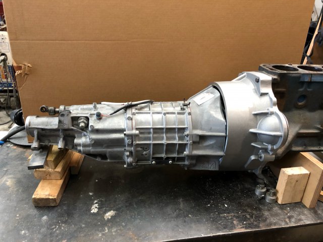
So the first ten bell housings have been sold and shipped to Godzilla Raceworks who is a dealer on these. Those ten are all sold. He offers the bell housings as well as the rest of the stuff needed for the conversion. I sell the bell housings direct but I don't stock nor get involved with the rest of the stuff. The bell housing and modified front cover is $1110.00 plus shipping. It comes with all the necessary bolts. You will need to source a shifter, crossmember and driveshaft. If you have a brand new takeoff front cover from a CDXXX I will accept that as a core and credit $135.00. I do not accept used covers as a core. I have an order placed at the foundry for ten more bell housings and if you want to preorder you can contact Godzilla. I don't do preorders since I don't want to be bothered:). I've finally attained cranky old man status and I'm loving it. I'm also in development on adapting the Aisin TL70 6 speed out of the BRZ. It's basically going to be the same setup as the CD009 conversion wise. The biggest difference is you don't have to cut up the tunnel for it to fit but it won't take nearly the abuse that the CD009 will. Here is a shot of the mockup as it currently sits. I'm pretty certain this is a workable solution for people that have lower HP builds but want the ratios a 6 speed affords. As soon as I get the next ten CD009 bell housings done I'm going to jump on this.
-
What it takes to get there is not going to answered here most likely because it is a list that is long. The absolute best advice I would give you is to contact Datsunspirit. Pay the price they quote and you will get what you want. It will be expensive. Plus they work directly with Jenvey. This is going to sound harsh but it is reality. If you are asking here then you probably don't have the skill set ( I don't) to actually leverage the different opinions that may be presented and actually build this type of motor. Getting to 9K reliably is a really heavy lift in my opinion. Getting to 7000 is easy. That that extra 2000 is where the real talent comes in. I'm going to rephrase your question for you: Question for those that have motors that go to 9000 RPM's. What did it cost:)
-
And now I hate you:)
-
This is pretty standard in my experience for all suppliers during Covid. None of the Z car parts places are fully stocked. I have the same issues with non car related suppliers as well. Except of course Mc Master Carr. They are a national treasure:)