Dat73z
-
Posts
852 -
Joined
-
Last visited
-
Days Won
8
Content Type
Profiles
Forums
Blogs
Events
Gallery
Downloads
Store
Everything posted by Dat73z
-
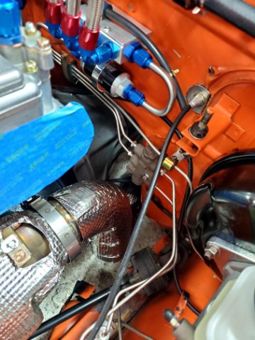
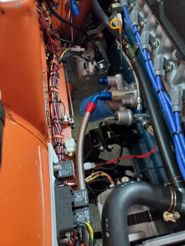
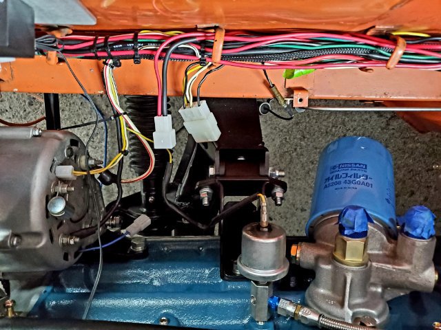
Had an hour open up this PM so I got the surge tank off and flushed then tightened the rest of the lines. I already flushed the stainless hardlines with acetone after I pressure tested the fuel system. Last thing is to set timing. I think that's about it until my buddies can make it out in a week or two. The strategy will be to fire it up and sync the carbs, let it heatcycle/burp the coolant then fully cool down, recheck torque on all fasteners, fire it up to check everything over, surge tank on and we're boosting. There are some areas I want to make some heatshields for, like the brake distribution block on the firewall. Not sure if I want to get into that or focus on other areas around the car. Probably no more turbo updates until it's back on the road for shakedown.

-
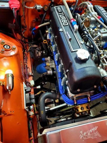
Out of time for today but I did manage to prime the oil system. Turbo and head are getting oil and pressure is building. I found it interesting Rebello did an internally oiled cam with spray bar. Little by little day by day... 20220625_113037.mp4
-
This morning my wife postponed our day out to tomorrow so I went through the oil system one final time. I flushed all the lines and checked torque for all fittings. This afternoon I'm going to prime the system to ensure oil is getting to the head and turbo. Lots of small details to cover before the first start.
-
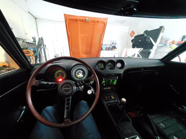
Tonight I started buttoning up the dozen or so minor things around the car which needed to get done. One of which was the boost gauge illumination.
-
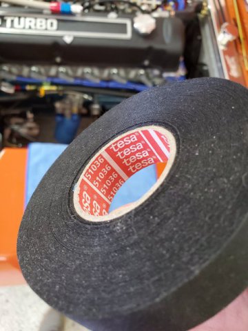
Got the harness back in and verified all circuits work. I ended up relooming the headlight harness with the Tesa tape as well. A couple more sub harnesses to loom in like the fans and the electrical is complete. I think I may go for a first start this weekend if time permits. Really since I took the entire car apart for this build I should put a wrench on everything one last time just to be sure, especially the driveline.
-
This morning I was able to finish looming the harness. I really liked how the Tesa tape laid down. I had an oopsie on one section and the tape doesn't leave any residue but sticks to itself really well. Before I reassemble for the last time, I'm going to flush out the cooler lines just in case. I've read/heard a lot of horror stories over the years of finishing a build and some junk in the lines grenades the motor.
-
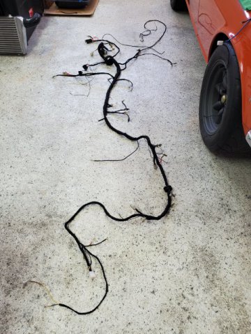
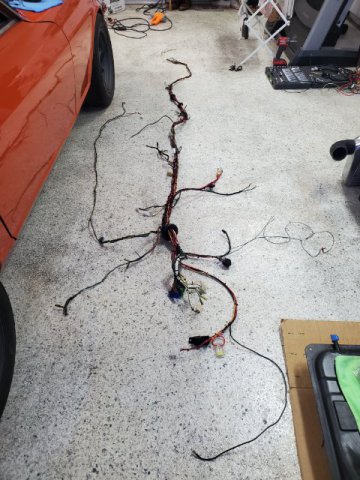
This morning I pulled the harness out of the car for looming. I'm going to depin a couple of unused connectors from the MSD harness and then I think it's good. It feels like a big day, a lot of work over a week to get to this point. Fortunately I have most of today off work but unfortunately my back is taking a beating from all this. Going to see how far I can get today. Losing patience, really want to just get it done but also done right since I'm already at the tail end.
-
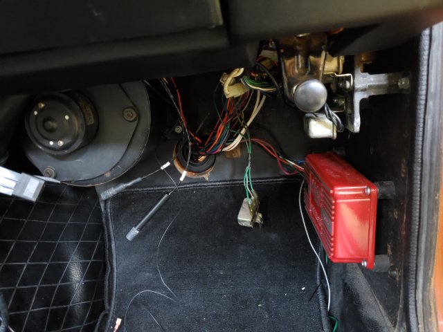
My oil pressure switch came in the evening so I wired it up. I realized there is one three prong relay in the cabin dangling which I can't remember where it bolts up. There's a phillips screw on the floor so it must go somewhere on the pass kick panel. Once I figure out where that goes and finalize the wire lengths there then I can pull the harness back out. Edit: it is the horn relay and it gets tucked way back in there
-
After that detour, last night I was able to integrate the new fuel pump signal subharness into the main harness and get it organized. Tonight I'm going to pull the harness for the last time and start looming.
-
This morning I added the breakout for the oil pressure fuel pump cut switch. I saw online O'Reillys can get the 3 terminal sensor within a day or two so I'll call and order that today. I also need to get a different color wire for the pump relay trigger so I don't confuse myself in the future. There is currently 12v starter solenoid (under heat shrink to indicate) and 12v switched ignition hooked up.
-
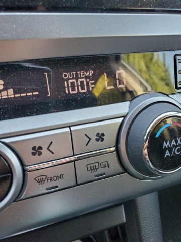
Didn't get much done tonight mainly because it was 100 degrees out when I got off work. But I did manage to pull out the 73 add on fuel pump harnesses and relays. I think I'm going to run the new wires into the harness and trim them to length once the oil pressure switch gets in so I can keep moving forward
-
Thanks, that means a lot. Slow and methodical is how I approach things I dislike such as wiring and bodywork so hopefully I won't need to redo this again anytime soon. After some further thought I think I'm going to completely eliminate the late 73 fuel pump add on harness and relays. Wire in a dedicated oil pressure switch instead and remove all that factory complexity. Unless there is a compelling reason to keep it that I'm missing. Now to order an oil pressure switch and wait for parts again.
-
Thanks @AydinZ71 The OE style connectors are because I already have a big box of them. The strategy I'm working is to get the harness routing and shape exactly how I want it with the zip ties. I will then pull the harness back out of the car and loom with this Tesa tape, snipping off the zip ties as I get to them. I think I have like a dozen rolls of this stuff
-
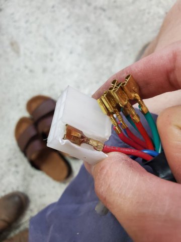
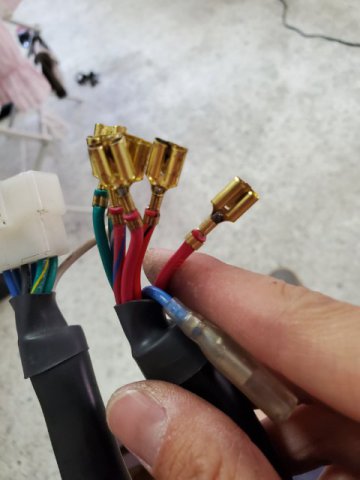
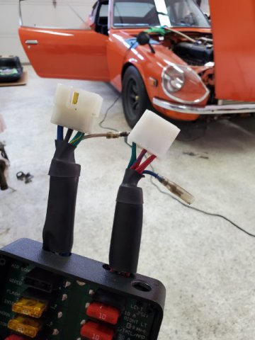
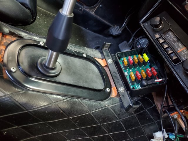
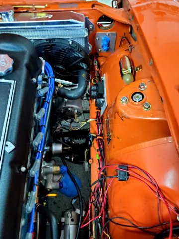
Over lunch I was able to tidy the wiring to the firewall. I also forgot my friend who shell swapped a couple years ago gave me a blade type fusebox as he couldn't use it in his S1 shell. Unfortunately his old car has some wiring issues and there was one connector melted to the plug. Through the magic of crimping and soldering I was able to restore the fusebox. All circuits work and now I can use blade style fuses.
-
This morning I continued with organizing the harness accessories. Eventually I want to fabricate some power/ground busses and a relay panel behind the dash, but I didn't want to get into all of that for this phase of the build. I think I need to get some round head allen hardware for the terminals as the bolt heads press against the terminal covers. A minor nickel and dime annoyance
-
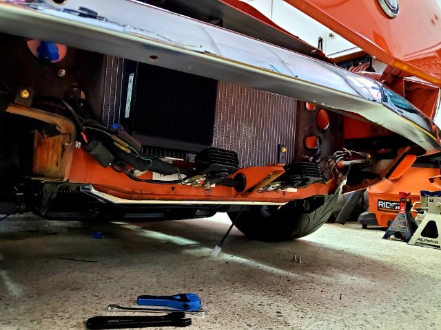
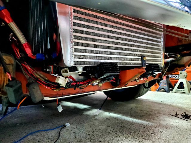
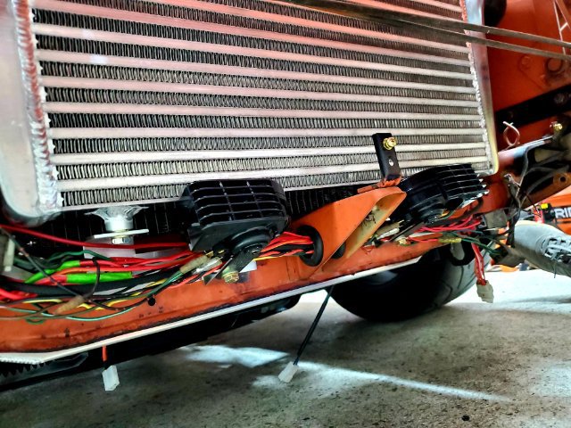
Out of time tonight but I managed to get the harness organized up to the breakouts for battery accessories. Originally I was going to integrate all harnesses into one but I've decided to keep the fan and headlight harnesses separate for serviceability. I was also pleased to find my routing and mounting choices for the oil cooler lines and intercooler piping made working in the area a breeze. Really hoping I can get through this in a couple more evenings because leaning over the fender and crawling around is killing my back
-
This evening I started back in on shaping the harness. I replaced a few more connectors with OE crimp style. I think this will take a few hundred zip ties, but the harness seems to be holding the bends I want. I really dislike wiring generally but I'm trying to stay motivated on this part of the build
-
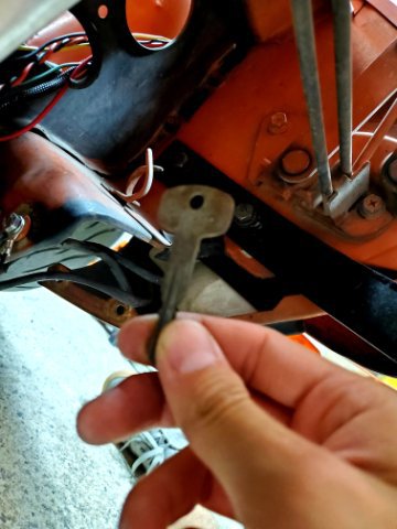
Tonight I had a few minutes to keep working the harness and got it mostly routed around the coolers. I think it's been almost a decade since I've owned this Z. When I purchased the car the PO was feeling under the fenders and told me there was a spare key hidden somewhere but he couldn't find it. Lost over 30+ years but I guess I finally found it
-
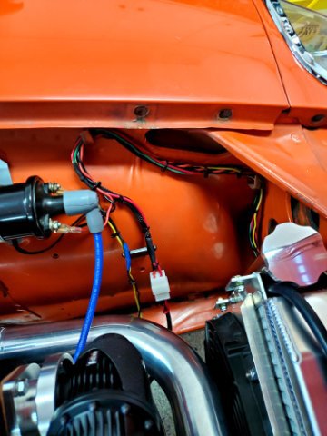
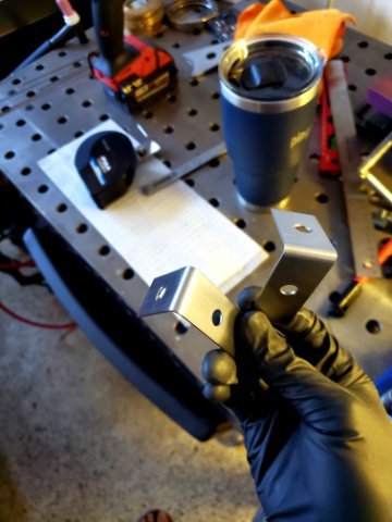
This morning I got up early and kept working the harness before heading out for Father's day. I forgot that I had made some custom horn brackets for PIAA horns as the turbo cooler packaging now takes up the space for the OE horns. The brackets I originally prototyped out of AL. The final version I made is 1/16 SS plate for rigidity. The brackets postion the horns to clear the intercooler and valence with a gap, and also helps to locate/support the harness behind so a multipurpose bracket
-
Had 15 mins after dinner and sorted the ignition system. I managed to pull the curves down that the engine ran on during the dyno. I think at 9-10psi it was at 350hp and trq. The curves are fairly typical for this type of setup including the map advance off load, the only difference really is the map section for boost retard. I also came to the realization that technically I could put some fuel in, fire the car up, and go for a drive right now. After all of that though I'm going to stay the course and finish this off right. Tomorrow I'm going to keep working the harness and prepare it for looming. I should also probably get the paperwork in for the tags and insurance. I haven't checked 240z prices lately but I'm going to assume I should increase my coverage anyways after all of this.
-
And I am an idiot. Shortly after my last post I realized my headlight relays were on the negative terminal. One circuit left to go which is ignition. Hopefully I can get that done tonight
-
This evening I was able to work on the harness a bit more. I'm down to the last 3 circuits which need to be addressed before I start tidying things up: 1. Fan Controller - forgot a ground whoops 2. Ignition system - it seems the green/white wire which I thought had 12v ign has nothing so I'll splice into the black/white upstream 3. Headlights - no idea yet, I can hear my headlight relays clicking but I'm only getting like 0.03v Starter and everything else including the radio and power antenna work. Really brings me back to when I used to drive this car every day. Hopefully again soon 20220618_180145.mp4
-
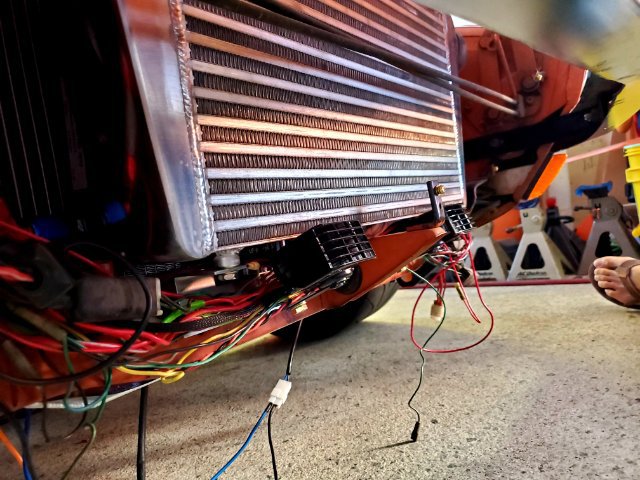
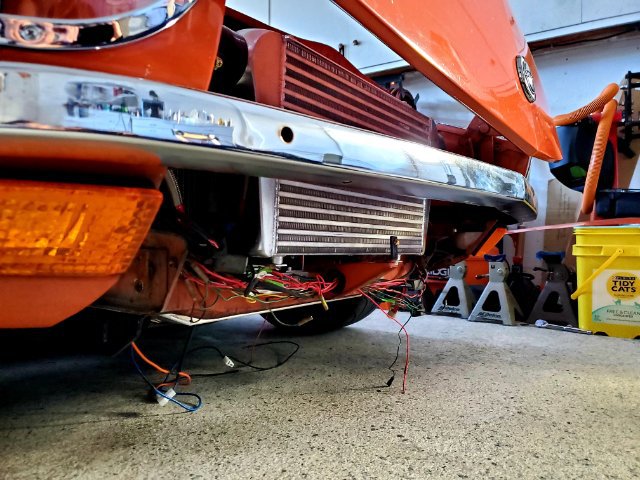
This morning I got most of the harness routing complete and tested. Wiring is probably one of the easiest but least enjoyable build aspects for me, next to sanding and bodywork. I rerouted the harness through some grommets on the valence support as the cooler packaging now takes up the original harness area. I think the strategy will be to zip tie every few inches to hold the shape of the harness/bends. Then when I pull it back out to loom, snip the zip ties as I get to them with the harness tape
-
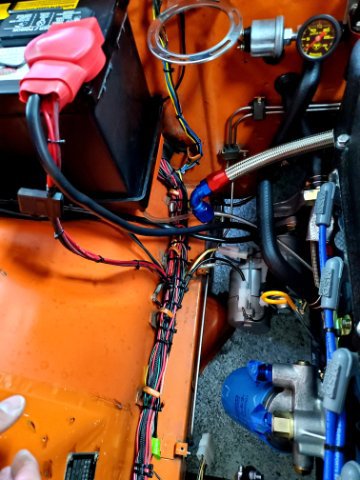
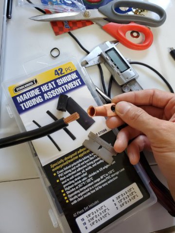
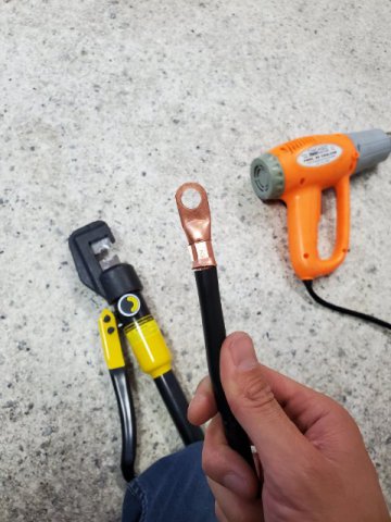
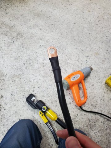
Thanks @AydinZ71 I think I actually have something similar left over from when I set up my tig machine. I seem to recall it was RV cable or something. Tonight I made some battery cables and hooked up the major circuits in the car. So far so good and no smoke so the gremlins get to stay in my car 😁. Originally the cables were supposed to be temporary but I may just run them. I took an old set of cables I had and cut the tired ends off on a bandsaw. Then I hydraulic crimped some autozone special lugs on the ends and protected them with marine style heat shrink. It's been a few months since I started this but I've already cleaned up the harness and replaced all the connectors and crimp connections. Next steps are to test each circuit and ensure I'm happy with the layout in the car. Then pull it all out to loom. 20220617_203734.mp4
-
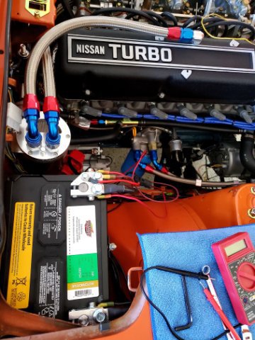
I used leftover silicone hose, clamps, and a barb fitting from when I was doing the turbo vacuum lines to plumb in the overflow tank. I forgot that I had ordered some new battery terminals as they were delayed for a few months due to supply chain but they came in earlier this week and also fit perfectly under my terminal boots. I'll take this as a sign to start back in on the wiring. I rebuilt the harness a bit with all new connectors and a dedicated 12v feed to the fuel pump. With all of the hard parts in place I'm going to work on finalizing the re-routing of the rad support area wires around the cooler packaging + looming