-
Posts
208 -
Joined
-
Last visited
-
Days Won
2
Content Type
Profiles
Forums
Blogs
Events
Gallery
Downloads
Store
Everything posted by 280Z-LS3
-
280Z build w/ LS3 and 2015 Mustang spindles/8.8
280Z-LS3 replied to 280Z-LS3's topic in Gen III & IV Chevy V8Z Tech Board
Cringing at the description of that crash. Does not take much to get into trouble. Physics is a bitch... I am stealing many elements of bjhines' cage and chassis stiffening. Tying the TC buckets to rockers, upper frame horns to rockers and strut tower to above sway bar frame rail area with 1.5"x0.065" DOM. I think this size tubing will give enough strength while minimizing additional weight. I think you are suggesting adding a tube from rocker (connected to the TC tube) to frame rail along the floor pan where it starts to angle up which is easy to do. Adding structure from rocker to trans tunnel under seats is easy too but how to carry that strength across the trans tunnel? Any ideas other than trans mount? Having the driveline and exhaust mocked up will certainly help determine what is possible. -
280Z build w/ LS3 and 2015 Mustang spindles/8.8
280Z-LS3 replied to 280Z-LS3's topic in Gen III & IV Chevy V8Z Tech Board
Thanks Richard. Really enjoying building all the modifications and applying the knowledge I have learned here on HybridZ. -
280Z build w/ LS3 and 2015 Mustang spindles/8.8
280Z-LS3 replied to 280Z-LS3's topic in Gen III & IV Chevy V8Z Tech Board
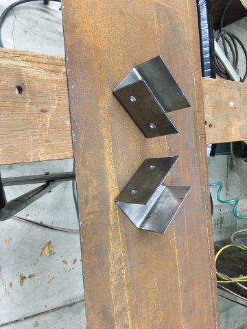
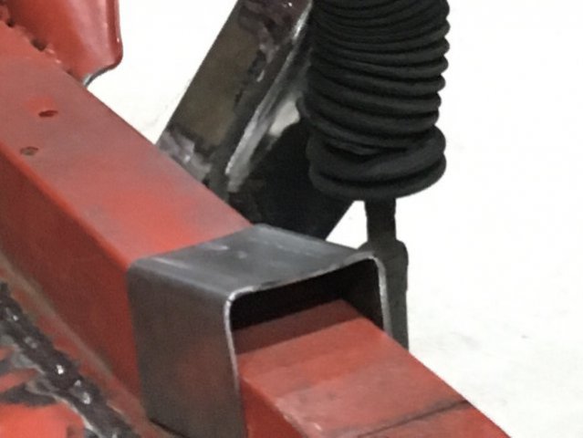
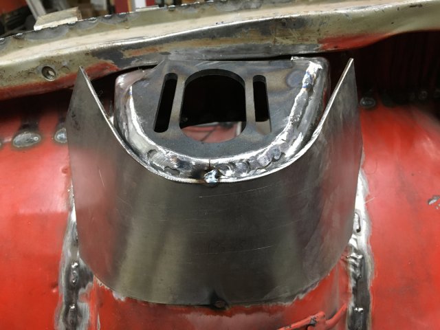
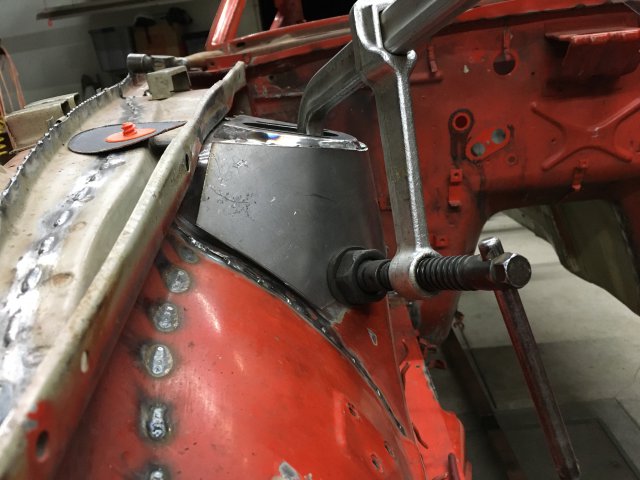
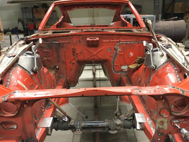
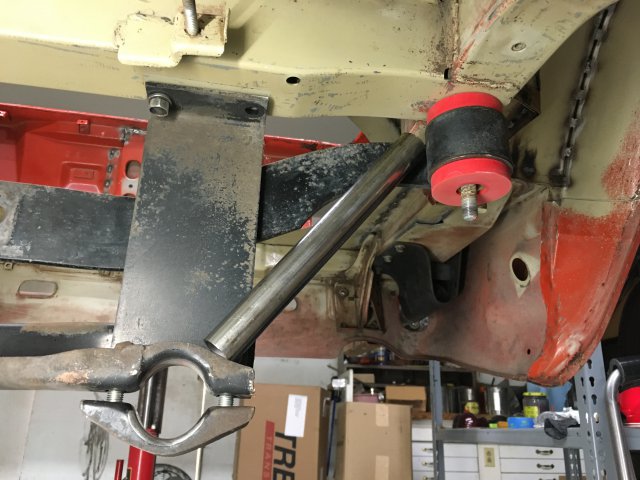
Started in on the chassis stiffening base plates. Formed up some brackets/base plates made of 12 gauge (0.101") to slip over the frame rails to support the roll bar area and to wrap the top portion of strut towers. I tack welded the plate on then muscled them a bit to start wrapping around tower. After about 30 degrees of wrap needed a BFH to wrap to a point where a clamp could finish drawing the plate to the tower. Been thinking about transverse link bracing/re-enforcement. Ordered up some tubing which should arrive in a few days. Here is the rough idea. Would also like to add tubing in a X shape between link mounts but need to get the diff back in to verify clearance. -
ANOTHER Datsun Z/LS3/T56 Swap Thread
280Z-LS3 replied to Ironhead's topic in S30 Series - 240z, 260z, 280z
Does the wax smell as bad as I've heard? -
280Z build w/ LS3 and 2015 Mustang spindles/8.8
280Z-LS3 replied to 280Z-LS3's topic in Gen III & IV Chevy V8Z Tech Board
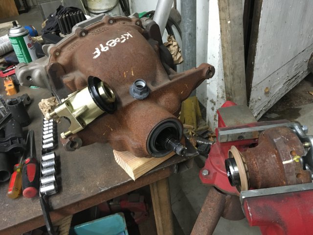
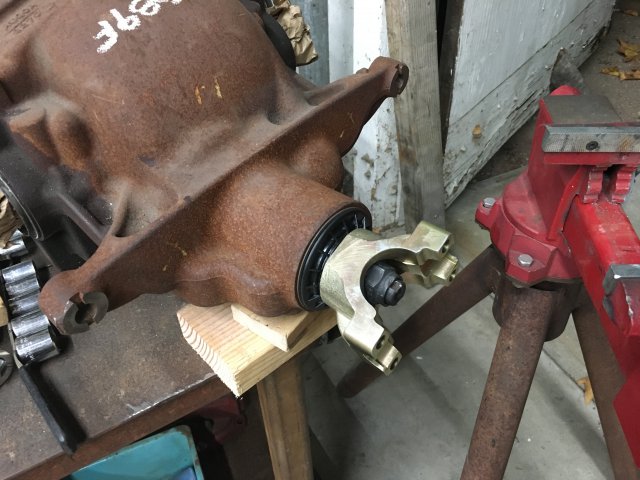
I placed the stock yoke in a vice to hold while removing pinion nut and reinstalling new yoke. Follow the directions for the Ford kit I mentioned in an earlier post. Basically, measure the torque to rotate pinion gear before removing nut and try to match that amount when installing the new yoke. Torque and check in increments so you don't over shoot. Over shooting will further crush the crush sleeve which will then require replacement, that means tearing the whole diff down. -
280Z build w/ LS3 and 2015 Mustang spindles/8.8
280Z-LS3 replied to 280Z-LS3's topic in Gen III & IV Chevy V8Z Tech Board
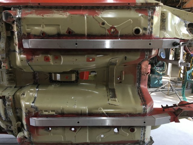
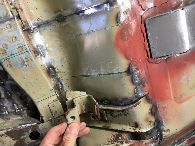
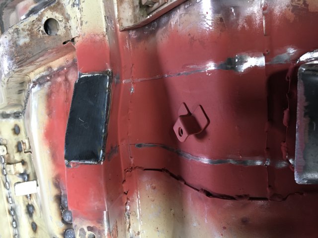
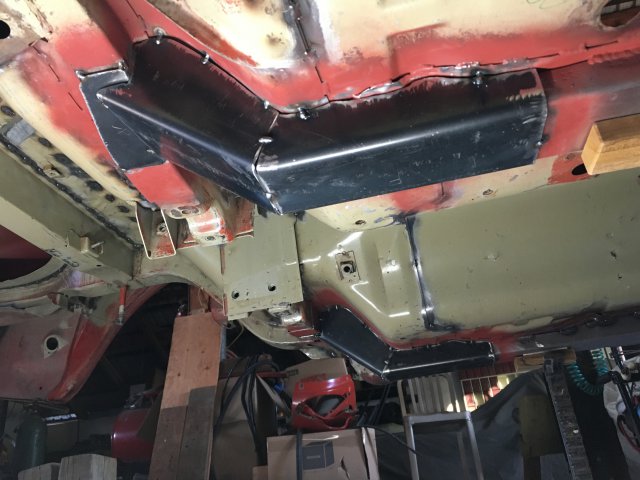
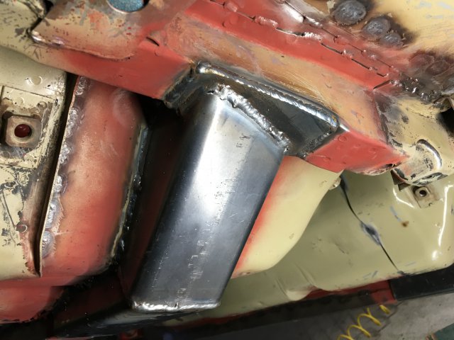
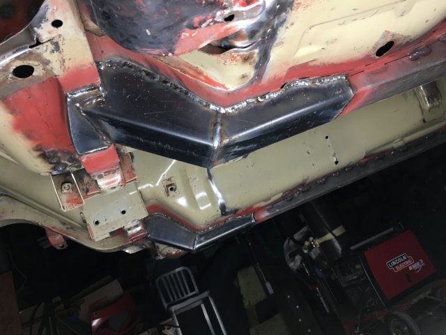
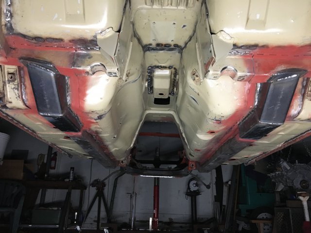
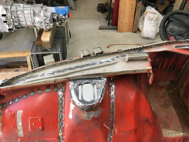
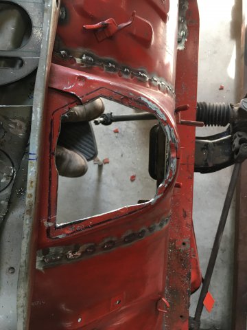
Finished up the seam stitch welding, what a time consuming job! I approximate at least 20-30 hrs invested, maybe more. Also welded in the Bad Dog frame rails and subframe connectors but before doing so I leveled the body on jack stands just to make sure no stress was flexing the body. Noticed a big increase in body stiffness while re-leveling on the stands after stitch welding. The first initial leveling to prepare for stitch welding the body would flex to sit on jack stands and after it pivots on the higher points. Conformation that all that time and effort was not spent for nothing I welded in the Bad Dog frame rails last because was contemplating incorporating some captive nuts inside the rails for the trans mount. After giving that idea more thought the complexity of pulling that off just killed my motivation. Instead going to build the trans mount off of some extra support structure for the floor pan. The bottom of the S30 chassis is a weak point and would like to address this while cutting up the trans tunnel to fit the Cobra Suzuka seat (my 1975 has the intruding bulge into the driver's seat area). Heavy85, a member here, crashed his Z into a small boulder field during a hill climb event. He posted an in car video and after math photos. His crash hammered home the need to build some strength and crash protection below the passenger seats. Getting ahead of myself a bit as this has yet to be design... Here are some pics of progress to date. Some weld thru primer before install of frame rails Some standard primer on inside of BD frame rails. The drilled holes fit over the stock weep holes and were welded to close gap between frame rail. Had to remove the stock roll bar mount tabs for welding clearance. That's okay since the new rear bar will most likely mount behind diff. Welded the portion of plate beneath connector first. Again leveled body on jack stands before tacking connectors in place. Finished product. Off to get a beer, Cheers! -
280Z build w/ LS3 and 2015 Mustang spindles/8.8
280Z-LS3 replied to 280Z-LS3's topic in Gen III & IV Chevy V8Z Tech Board
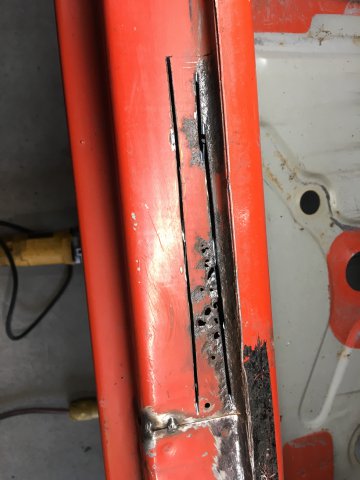
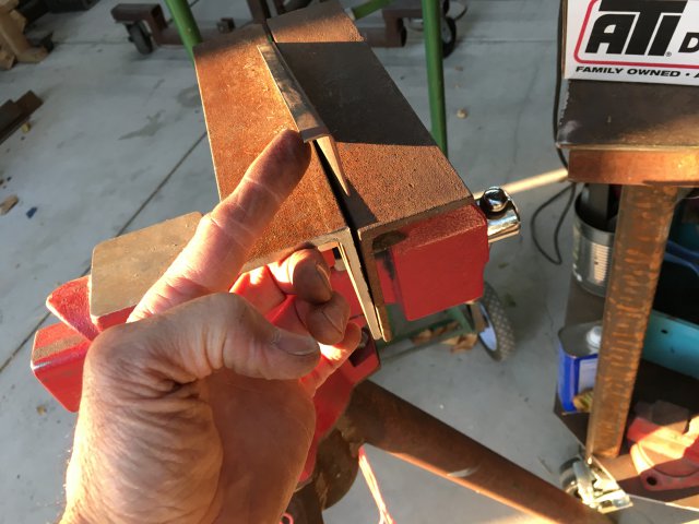
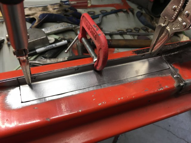
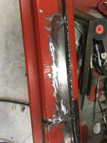
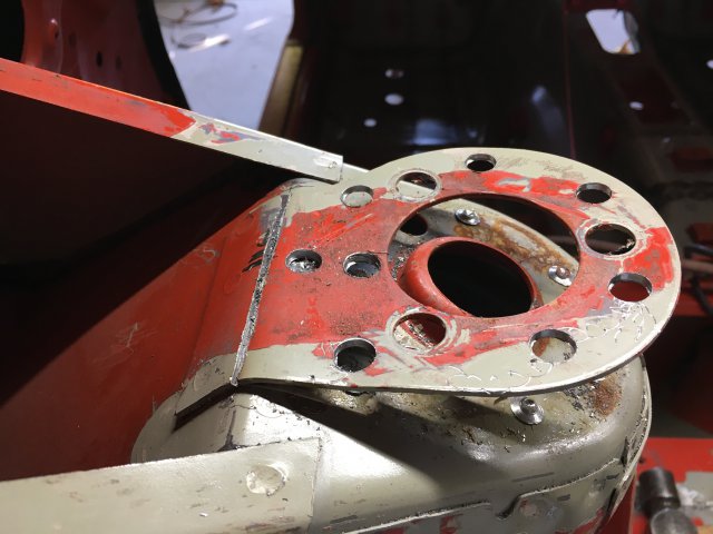
Repaired the rust damage on passenger door sill. Been pouring all my time into the build so haven't had time to fabricate the DIY sheet metal brake from the pieces I gathered at the local structural iron fabricator remnant pile. So to form the patch I used some scrap angle and vice to form the 20 gauge patch piece. -
Thanks jhm, I have seen those pics and stealing plenty of ideas, lol. Of particular interest is bjhines's car/cage he built back in 2006, I like his cross bar that contours firewall just below windshield. I can just see myself wasting a bunch of tubing trying to get that bar fit properly... I would like to have the front strut towers triangulated off that bar. I don't plan on having a node at that point taking load back to rear strut towers because it will intrude on passenger space. Not the best design but compromises are going to be made. But that's a whole different conversation... Since my plan for the Z is a street legal car I plan to target autocross, HPDE and maybe Time Attack. If I decide to go deeper into competition, and have not broken too many rules with all modifications, I'd like to know my cage is legal. But first and fore most want it provide safety.
-
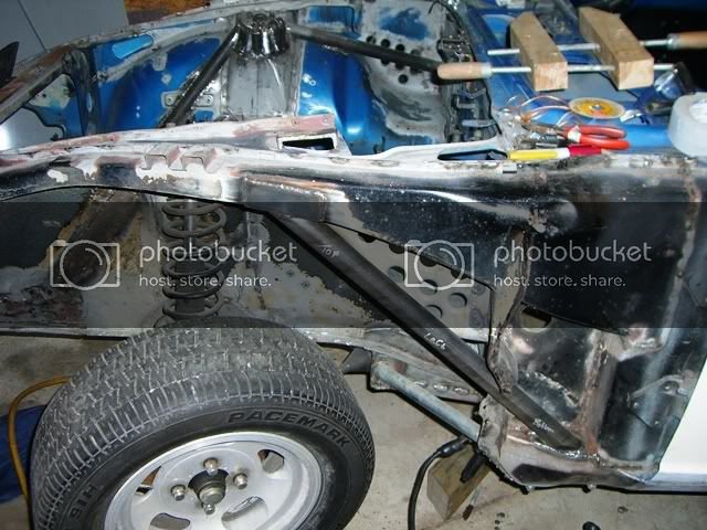
Going to start chassis stiffening and would like guidance on tube and plate thickness. My main cage will be DOM 1.75"x0.095". I hope to be under 2800 lbs. but figured better safe than sorry. What is minimum plate thickness for boxes that support main bar and forward a-pillar bar? I believe 2020 SCCA rules say between 0.080" and 0.25". Tube size and thickness for anything other than cage, DOM 1.5"x0.065"? And thickness for the additional chassis support plates for stiffening tube?. Some areas I am considering are from radius arm bracket to rocker panel, wrapping front strut tower to support forward frame rail and rear ward roll cage tie ins, tops of rear shock towers. Edit: Adding info from searches. Roll cage mounting plate min. of 0.080" thick, no more than 100 sq.in. and no less the 9 sq.in.
-
Don't think I could incorporated a Flying Miata type brace into my build but also have not given thought to side pipes. I like the idea of anything under the car hugging the floor pan. Building added structure inside the cabin is interesting too. I have a Cobra Suzuka which the manufacturer states it does not require a back brace. It's a fiberglass seat and don't know if they are compatible with rear bracing.
-
Floor strength is something I want to enhance when installing my seat. I will need to modify trans tunnel encroaching into the seat area anyway so may as well try to strengthen the floor. The only idea I have so far is forming up some sheet metal like the original transmission mount and have it tie in the frame rails. More ideas are welcome. I was fired up to try hill climb racing until I saw Heavy85's video of his crash!
-
Ironhead, The first thing i purchased for my Z after buying the car years ago were Bad Dog frame connectors. Fun fact, the owner of Bad Dog came across an undeveloped film roll in a garage somewhere and that is where those pics came from. Talk about hidden treasure, right? I too noticed that every seam on the BRE was fully welded contrary to current advice of stitch welding. John Coffey, famed Z car wizard, mentions that fully welding the seams relieves the forming strength/stress in the steel weakening the final product. I don't know squat about metallurgy... AydinZ71, I would love to have the ability to use Solidworks but for now I live vicariously through others like Noah Dropkin who designed my 2015 Mustang front spindle swap. Completely amazed what he does with 3D scanners and Solidworks. Maybe new frame rails with tie-ins to cage can help strengthen up your 71. Curious about location and extent of rust.
-
280Z build w/ LS3 and 2015 Mustang spindles/8.8
280Z-LS3 replied to 280Z-LS3's topic in Gen III & IV Chevy V8Z Tech Board
Thanks for the kind words, held keep me encouraged... AndinZ71, theoretically the engine/tranny downward angle and pinion up angle should be equal. For example, if engine/trans points down 2 degrees the pinion should point up 2 degrees. Cars with less than perfect alignment run without issue and are even purposefully built unequal such as rear leaf spring cars to compensate for flex upon acceleration. Having both at zero degrees is not recommended either because then the u-joints don't spin thus placing constant load on a few needle bearings. Check out this cool video demonstrating the concept. https://shiftsst.com/blog/post/driveline-angles.html Today's task is getting the 8.8 back into car and dialing in pinion angle, shooting for around 2 degrees. Then it's off to fabbing up the engine and trans mounts. -
280Z build w/ LS3 and 2015 Mustang spindles/8.8
280Z-LS3 replied to 280Z-LS3's topic in Gen III & IV Chevy V8Z Tech Board
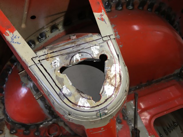
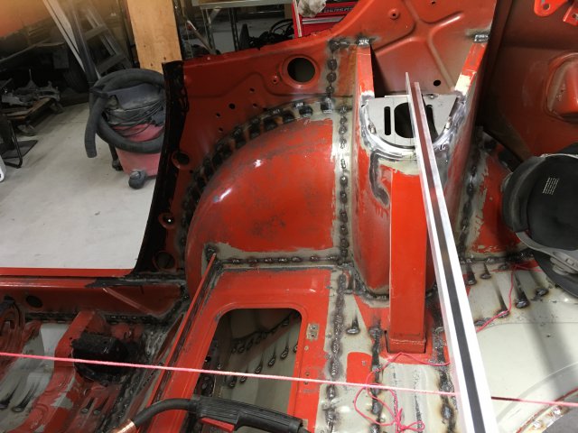
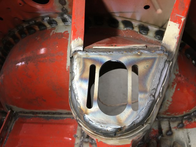
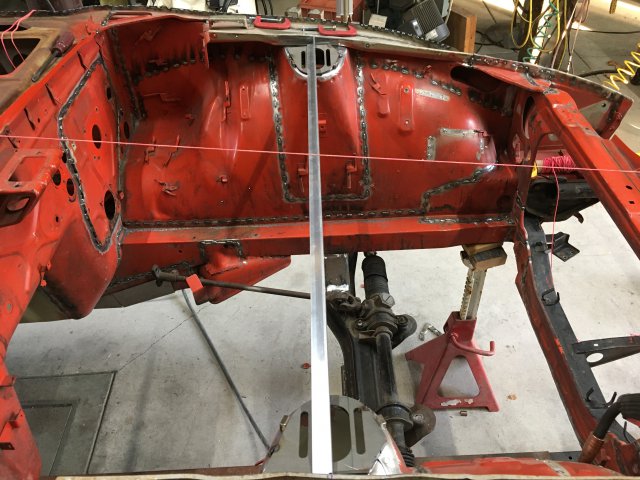
Finished the weld in camber plates. Must admit I agonized over the installation spending a long time getting the plates square to centerline of car and, for the fronts, the same distance from firewall. The fore/aft placement of the rears were determined by center of strut hole on top. I initially used the midpoint between the frame rails and mustache bar studs for car centerline. I could not get the front camber plates both square and equal distance from fire wall. Switched to using the mid point between the front and rear strut towers and things came into alignment much better. Questioning the effort I made to get the plates aligned so accurately (within 1-2 mm) given this is a mass produced 45 year old car known for a flexible chassis. Well, at least I can say it was done accurately and best to my ability. Started with rears. My 75 has the thin top sheet metal that was removed exposing the larger gauge flat top. I then placed a piece of aluminum angle iron across top to fit plates perpendicular to car centerline. Did not have to fight seam sealer contaminating welds so they welded up nice. The fronts were done in a similar fashion as rears. Darn seam sealer reared it's ugly head making the welds less visually appealing. Tuned the weld up with an abrasive disc and will bondo the remaining minor imperfections before paint. -
280Z build w/ LS3 and 2015 Mustang spindles/8.8
280Z-LS3 replied to 280Z-LS3's topic in Gen III & IV Chevy V8Z Tech Board
Swapped out the stock Ford pinion yoke for the Yukon 41040 yoke (1993 Ford F250) which uses the large 1350 u-joint. I followed the instructions for M-4851-M8A Super 8.8 IRS Mustang Automatic Pinion Flange Kit that can found on Performanceparts.ford.com. -
Wow, you still have flex with a full cage?! Can you share a pic of cage design? Do a search for "chassis stiffening" for everything you need to strengthen chassis.
-
Settling on two rear end options...
280Z-LS3 replied to AydinZ71's topic in S30 Series - 240z, 260z, 280z
Good choice! -
280Z build w/ LS3 and 2015 Mustang spindles/8.8
280Z-LS3 replied to 280Z-LS3's topic in Gen III & IV Chevy V8Z Tech Board
Tamco says they are pearls. The particles are very small. The Blood Diamond Metallic Red I sprayed out has noticeably larger flake particles. -
280Z build w/ LS3 and 2015 Mustang spindles/8.8
280Z-LS3 replied to 280Z-LS3's topic in Gen III & IV Chevy V8Z Tech Board
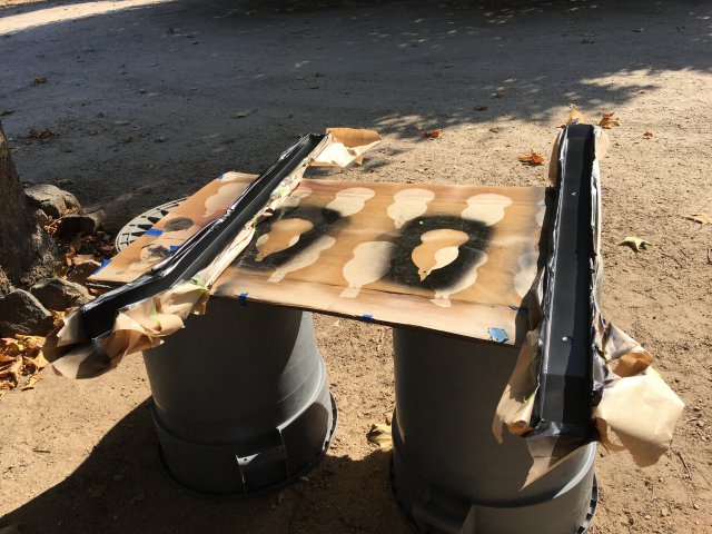
Light at the end of the body stitch welding tunnel! Competed most of the stitch welding and had a question as to whether or not to weld the to halves of the wheel well from the tire side and also along the floor pan to rocker panel from under the car. While waiting the "yes" answer to that question I moved on to finish fabricating the rear frame connectors. I spent some time a few weeks ago making some nice card board templates then transferred them to 12 gauge sheet metal. I cut them out and used the DIY press brake to form the sides. Damn, they looked good! However, after bending the tops to close the gap it became apparent both connectors had a twist totally ruining the fit. I can only surmise the flexible cardboard used allowed twist that I did not notice. Good idea but poor execution... I cut off the portion that slips over the Bad Dog frame rails, bent up another two channels and proceeded to slowly grind away at the ruff piece. Cutting a 3D piece to fit into a 3D irregular cavity is difficult, exactly what I was trying to avoid with the templates. A few hours later I had one side done. Not looking forward to spending that amount of time for the second a thought came to me. Call it a moment of clarity, epiphany or just pure genius, lol. The car is symmetrical along the rear frame rail so I traced the finished connector on the blank as a mirror image and presto, it gave me the needed shape with just some minor grinding. I added a small plate to the top of the rear frame rail to help strengthen the connector to rail connection. Purchased a few "spray outs", small 2oz cans of base from Tamco in 6 colors (Sangria, Rock-It Red, Blood Diamond Red, British Racing Green, Sinister Red and Green) I only used black base speed shapes so most came out really dark. I did 3 and 4 coats of base to see if an added coat was needed and hit them with some old SPI clear from last build. I think 2 coats could be sufficient so will spray those out again on white, gray and black bases to see if I can lighten up the darker colors. I like reds dark so no need to re-spray those. Not going to mess with metallic paint because I can see differences is how the flake layed down with the Blood Diamond Red on a small speed shape and can only imagine how badly I would screw up a whole car. I am not the best painter... My favorites are Sangria and British Racing Green. The green needs to be on grey or slightly tinted green base to reduce darkness. Going to test a few more colors before I make the final choice. The Sinister colors would make great racing stripe or accent paint. -
ANOTHER Datsun Z/LS3/T56 Swap Thread
280Z-LS3 replied to Ironhead's topic in S30 Series - 240z, 260z, 280z
Katech makes some nice pumps and they are proud of them as evidenced by price. https://store.katechengines.com/oil-pumps--accessories-c199.aspx Lingenfelter offers pumps too which look to be Melling. I have not really researched/verified if other manufacturers like Melling have an "upgrade" pump with increased scavenge like Katech. As of now I may have to hold off on the planned engine mods (cam and lifters) because of budget, spending more than anticipated. Big Surprise there! Not too bummed because the stock LS3 with 430/430 HP/TQ is still going to be a handful. Either way I am most likely going to hold off on replacing pump because the red line on road race/endurance cam should be below rpm which the stock pump starts to cavitate. The Manton trunnions are a must though and $300 is cheap piece of mind. LS1Tech is a great place for LSX info https://ls1tech.com/forums/ls1-ls2-ls3-ls6-ls7-performance-3/ Edit: I should have read the descriptions of Katech pumps before commenting on price. The pricey ones are for LT1 and LS7 engines. Katech is one of the best LSX endurance racing engine builders so I need to ask them rpm limits of their pump. I seem to recall being around 7500 but don't quote me. The LS3 "wet sump" type, which we use for our scavenge only dry sump systems, are $230. Again, still don't know if it's any better than a Melling which runs for about $180. Sorry I currently don't have a definitive recommendation between the two. -
I do have the car is on rotisserie so I will weld them up and have already removed most of seam sealer while scrapping under coating off. Being able to pull the body straight after damage is reason enough for me. Let's hope it doesn't come to that...
-
ANOTHER Datsun Z/LS3/T56 Swap Thread
280Z-LS3 replied to Ironhead's topic in S30 Series - 240z, 260z, 280z
The bronze bushing upgrade is a "piece of mind" item for me. One or two hours of labor and your choice between CHE around $180 or Manton around $270. I like the Manton for the larger bearing surface area. Oh, and you don't have to worry about changing push rod length, just swap trunnions and your good to go. The only other thing is the GM oil pump, it starts to cavitate around 6500 engine rpm. Don't think it will be an issue with your cam as I believe shift point is below. It's an easy upgrade in the future if needed... -
I am welding the over lapping seams on the body. Would like to know if it's correct practice to also weld the inner wheel well joint and the floor pan to rocker panel joint. These are the areas I'm talking about
-
ANOTHER Datsun Z/LS3/T56 Swap Thread
280Z-LS3 replied to Ironhead's topic in S30 Series - 240z, 260z, 280z
Another step closer... If I recall correctly you have a GM LS3 crate engine. Have you given any thought to upgrading the stock roller needle rocker arms? They are notorious for failing sending destructive needle bearings thought out engine. The easiest solution is bronze trunnion upgrade like CHE and Manton. The CHE is said to have a higher quality bronze while the Manton utilizes a larger diameter trunnion thus increasing surface area.

