

olie05
-
Posts
1629 -
Joined
-
Last visited
Content Type
Profiles
Forums
Blogs
Events
Gallery
Downloads
Store
Everything posted by olie05
-
I love the sound of the engine revving up. It sounds so smooth. That is bieng controlled by megasquirt right? I'm not digging all the engravings all over the engine, though... its like reading a book!
-
I stumbled upon this page, from youtube. A video of a running tc24-b1 is rare. Sounds surprisingly L-series-ey. It doesn't have that howl that the s20's have, but i guess that has more to do with bore and stroke than head design.
-
hehe i have that problem. Anyone who gets in my car cant turn the key because the lock cylinder won't turn unless you have the key in *just* the right amount, and when they try to start it, it will just click unless you push the key in as you are turning. I guess i'm the only one who's supposed to drive my car
-
My clip specs: 2.5" mandrel bent exhaust (MSA turbo exhaust system) "turbo" muffler MSA 6-2-1 header Crane 272/282 split cam, .450" lift N42 block / head 10.3:1 CR Megasquirt n spark extra
-
Here is an exhaust sound clip of my car revving.
-
I read the same thing in the megamanual and decided to set my prime pulswidth to .1, standard prime on power up, and the cranking pulsewidth at 80 degrees is 4.6ms. This gets my car started with very slight push on the throttle, and it will idle from a cold start after that. I would start by checking cranking pulswidths, and moving on to the ve table from there. What code ya running? what's your set up?
-

Shell Ferrari commercial - turn up you speakers!
olie05 replied to pparaska's topic in Non Tech Board
I worked a corner at Texas world speedway, and there was a 914-6 that would do the exact opposite of that... As it was approaching it would sound like a really HIGH revving engine, and as soon as it passed it would turn into a really mean deep note. -
Yep that was the problem. The ground (my common) was connected to one end of the filaments, so when the power was applied on my hi beams, the current would run through both filaments. The solution: Tested with two wires off my battery to see which pins were the dimmest (running through both filaments) and made sure NOT to have those together in the new wiring. I'm about to go find a nice dark road to drive on and test the new (to me) hi beams!
-
Maybe i'll get off my lazy butt and go check the wiring... But I wired the bulb harnesses (from the stock sealed beams) as per the factory manual, only reversing the polarity. Now with the H4 lights it seems to be Doing Problem "A" where it is running voltage through two filaments in series.
-
hmmm... The throttle butterfly doesn't have a "side" it sits in the middle of the throttle bore.
-
Which way to go in? (engine mods speculations)
olie05 replied to Blobber's topic in S30 Series - 240z, 260z, 280z
How often is the inspection? You could swap in an l28 and if they're really anal, slap the carbs back on when inspection time comes... I know the inspection guys around here have NO CLUE. -
the dude paid for the car, he's free to "modify" it how he likes, no?
-
Triggering EDIS-6 using a 72-2 cam wheel in a four stroke?
olie05 replied to hoohaa's topic in MegaSquirt
In the case of having three ignition outputs, wouldn't it be better to actually waste the spark? i.e. not send full spark energy to the exhaust stroke piston? After all, this is the point of wasted spark, and you are only asking the charging system for power for one coil, rather than two. so rather than LS-1 or GM truck coils, something like this (assuming it has abuilt in igniter: -
Aero effects that increase lift on purpose.
olie05 replied to ZR8ED's topic in Windtunnel Test Results and Analysis
It would seem to me that the drag caused by the aero package in question would outweigh the beneficial drag lost in rolling resistance. If you start with these two equations: Fr=FW and Fd=(1/2)*Cd*A*P*V^2 where Fr=drag due to rolling resistance F=coefficient of drag at the wheels W=Mass of vehicle Fd=Force due to aerodynamic drag Cd=coefficient of aerodynamic drag A= frontal area P= air volume density V=Velocity in question (highway speeds) Then get power required by Fd*V and Fr*V and compare the two results. Since Power required due to aerodynamic drag is a function of V^3 it is going to be really hard to reap benefits by increasing the Fd to lower the Fr at higher speeds. Also, in order to create lift, you have to create drag, which in turn increases frontal area and on top of that, it all gets multiplied by V^3. Seems better to invest in LOWERING the Cd, and create some sort of frictionless bearings... -Oliver edit... yeah tombarace14 pretty much summed it up... -
bump... anyone know?
-
I have searched for hours... thinking, Surely this topic would have come up at some point. I would like to know what size the nuts are on the two front differential mount bolts. These are the two bolts that go through the two holes in the front of the differential and attach it to the rubber isolator. I purchased a set of m10x1.5 and m10x1.25, but the correct size is M12. Now, before I go and buy m12x 1.25,1.5 and 1.75, I was hoping someone would know exactly what the pitch is supposed to be. also, it would be nice if there was some directory of bolt sizes. Just a thought.
-
Funny... I recently took OFF my tint. It was cheap, done about 3 years ago, and it was starting to turn purple. BTW I live in Houston and drive my car everyday with no A/C!
-
No way. I'm using the 83 turbo optical dizzy. I have a spare for you if you are interested. Just get a shaft and you're in business... no more headaches.
-
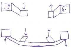
We have learned that the frame rails aren't the strongest point on Z cars from racers using thick anti-swaybars on non-reinforced frame rails. With the stock crossmember the torque of the engine is merely pushing up or pulling down on either frame rail. With a non-tied together design such as yours, when the engine torques over, each engine mount will not only pull up or down on the frame rail, but at the same time twist it. Here's a quick sketch to show what I'm talking about showing the reaction forces and moments at the rails: Your mounts certainly look like they will hold the power of the stock VQ, but eventually with the mounts rotating the frame rails back and forth you will probably see stress cracks forming near the mounting points. (assuming no reinforcement at the rails). my .02
-
-
Without the two mounts being connected by a crossmember, don't the mounts see way more stress than if they were somehow linked? I'm worried about the mounts twisting the frame rails.
-
The car idles now. The things that were changed were the injector constants, req fuel was too low, and i messed with some of the injector settings to get it to run right. VE bins at idle were too low as well. now to get it DRIVING! --edit-- also I'm much happier with the VB921 coil driver. I'm having less random sparks after the engine shuts down.
-
I swapped out the HEI for a new one ($15 autozone) And it did the same thing, so I went to a VB921 setup, and I still have the same problem... I don't think its the ignition anymore. I can hear the injectors firing at all times, so I guess the next thing to check would be fuel pressure.
-
I have a spare vb921 around that I might just wire in tomorrow. Its been a day full of cranking and nothing.
-
Wheel Show! Post your pics of you wheels
olie05 replied to k3werra's topic in Brakes, Wheels, Suspension and Chassis
This car looks familiar: found on the turbo rotary 510 page.
