

ktm
-
Posts
1725 -
Joined
-
Last visited
-
Days Won
3
Content Type
Profiles
Forums
Blogs
Events
Gallery
Downloads
Store
Everything posted by ktm
-
-
Curious...Which Income Bracket Do You Guys Fall In?
ktm replied to slownrusty's topic in Non Tech Board
Enough to be comfortable in So. Cal. -
Check ebay for the injector holders. There is a seller that has billet aluminum holders to replace the plastic ones.
-
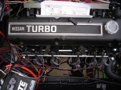
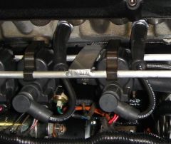
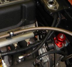
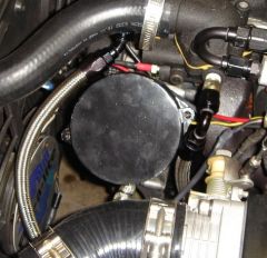
You can also use the LS-1 coils as well (that is what I am using). I came up with a slightly different method of mounting the coils: As you can see, you do not have to relocate the stock coolant hose. Electrically the coils (LS-1 and truck) are very similar if not the same (per Ron and z-ya). Ron is using the truck coils and I am using the LS-1 coils. You can pick up a set of 8 LS-1 coils on Ebay for around $80. You'll also need the plugs, which can be found for around $30 to $40 for a brand new, OEM set on Ebay (they come in the coil harness). I believe z-ya is mounting them in a different fashion as well. He was going to mount them off the valve cover, similar to the OEM GM setup.
-
-
I highly recommend buying a hoist that has caster wheels for both the front and back. I picked on up in June after using a conventional hoist (rental from Sunbelt Rentals) that only had casters in the rear. Casters on all four corners is a GODSEND.
-
I am running the LS-1 coils on my car in full sequential ignition. However, I am using the Wolf V500 ems.
-
Which color centers for my new CCW Classics?!
ktm replied to a topic in Brakes, Wheels, Suspension and Chassis
Polished for the same reasons Ron mentioned. -
nothing I do makes my clutch work!!
ktm replied to hondabait's topic in Trouble Shooting / General Engine
A new slave cylinder is only $20 if that is indeed the culprit. -
FYI, Mr. Injector on Ebay will clean, test, and bench flow 6 injectors for $80 shipped. He has very fast turnaround and great communication.
-
Added information on what wire(s) to tap into.....small oversight.
-
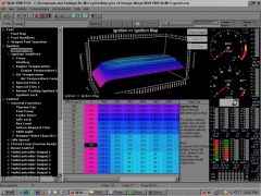
Racinjitter, Ron Tyler helped me with the base map. As I mentioned above, I have a spreadsheet that allows me to calculate injector pulse widths. This gave me an idea of the range I should be considering. Ron was the one who put together my startup fuel map. You can reference the MS forum for your timing map, as timing is timing with our engines. I will be more than happy to share my map. I was in the same position as you 3 weeks ago.
-
Updated with additional pictures and information about IAT, ETS, TPS, trigger ref. Correction about the MAP sensor. It is a 3 bar sensor (30 psi).
-
-
-
-
-
-
-
-
Gratuitous Photos of LED Dash Light Conversion
ktm replied to ktm's topic in Ignition and Electrical
Hugh, I only ran with the gauges at night twice so far. I am still shaking down my car and try not to run at night. It's harder to spot the police. Still, I did not notice any reduction in night vision. The reason I opted for blue as opposed to red or amber is that our gauges are lit by indirect lighting. The faces are black and the numbers and needle are painted white. Unless it was a bright red light, I was afraid that the gauges would be too 'dim' to see clearly. -
LED Dash Light Conversion As posted, here is a short write-up regarding converting the dash lights in an S30 to LEDs. It is relatively straight-forward and easy, though I will say that it is time consuming if you want to do a nice job. DISCLAIMER (borrowed from Afshin): First, electrical shorts can burn out your EFI and/or cause a car fire. I have no interest in anyone doing this and don’t know if it will work for you or not. I have no formal training and am only sharing what I did for myself. There is no guarantee nor should any inference whatsoever be made that anything posted below is correct or safe. Cliff Notes: If you done blown up yourself, look in the mirror for liability. Stock Lighting System First, a little information regarding the dash light system. The dash lights in a 240z (you will need to verify the lighting circuit for other models) get their power from the green with white wire coming out from the combo switch. This wire controls the side marker lights and parking lights. The lights are on a circuit that is fed power via a red with blue (R/L) stripe wire. The R/L wire connects to the G/W wire somewhere behind the dash by the speedometer or tachometer. I could not see the connection as the harness is still wrapped in tape. The R/L wire then connects to the dimmer switch (potentiometer) with a female spade connector (that is, the connector on the end of the wire is a female spade). Power is then distributed to the lights from the dimmer switch (the dimmer switch here is connected to the R/L with a male spade). The 240z dash lights only have one (1) R/L wire connecting to each light. The ground for the dash light is in the light receptacle itself. It is a small metal plate that makes contact with the gauge housing. The gauge faces are illuminated with indirect lighting. The light from the stock bulb is reflected back onto the face of the gauge from the black bezel in the gauge face. Understanding LEDs LEDs or light emitting diodes are peculiar little critters. They range in intensity and size, though size is not related to intensity. LEDs, while bright, have viewing angle limitations. You must find the correct viewing angle for your application. The viewing angle is a cone of light the emanates from the top of the LED. Some LEDs have a very narrow viewing angle but are incredibly bright. Turn signal lights, for instance, would be a good application for such an LED. For illuminating gauges, however, you will want an LED that has a broad viewing angle as this gives you some flexibility in their positioning within the housing. LED’s illumination characteristics are described by millicandela or mcd. The higher the MCD rating, the brighter the LED. I used 5000 mcd LEDs in my conversion. I would suggest that 4000 mcd is the lowest you would want, as any lower and the gauges would be too dim. You can not simply increase the voltage to an LED to increase its output; you’ll melt the LED (ask me how I know – accident). Saying that, LEDs are incredibly sensitive to voltage. Too much and you’ll fry the sucker, too little and it will not turn on. However, they draw VERY little amperage (20 mA is typical) and almost no heat is generated by an LED. LEDs ARE polarized however. The longer ‘leg’ of the LED is the cathode and the shorter ‘leg’ is the anode. When wiring up an LED circuit in series, the first LED or lead LED cathode is attached to the power wire. The lead LED anode then connects to the second LED cathode and so on, until the last LED anode is connected to ground. Determining You LED Circuit First, you need to plan out your conversion. How many LEDs per gauge are you going to install, the size of the LEDs, how are you going to install the LEDs, how are you going to wire the LEDs, how are you going to route power and ground the LEDs, etc. I opted for 6 LEDs in both the speedometer and tachometer, and 4 LEDs in each of the gauge pods. Once I determined my LED arrangement and planned out my circuit, I started shopping for LEDs. I bought my LEDs from www.theledlight.com. They have a much larger selection than www.Superbrightleds.com and had the LEDs with the viewing angle and luminosity that I was after. My LEDs are 5 mm, 5000 mcd with a 40 to 50 degree viewing angle (http://www.theledlight.com/5mmcoloredleds.html - the second item). They have a peak forward voltage (VF) of 3.5 volts and a minimum VF of 2.9 volts. Their amperage requirement is 20 mA. Note that the LED will have a brightness of 5000 mcd at 3.5 volts. At 2.9 volts, the brightness will not be 5000 mcd. So now you have your circuit planned out and decided on the LED, the next step is determining how are you going to wire up your LEDs and how to supply the correct voltage. This is the easiest part of the whole conversion. The charging system of a 240z theoretically provides approximately 14 volts. Using my LEDs above, I can wire 4 LEDs in series and ‘consume’ 4 x 3.5 volts = 14 volts. Thus, I do not need to drop my voltage to run 4 LEDs in series. If the voltage is less than 14 volts, my lights will not be as bright. However, if the voltage is MORE than 14 volts, I may be in trouble. My tachometer and speedometer posed a problem though. I am using 6 LEDs and I would need 6 x 3.5 volts = 21 volts to run all 6 LEDs in series. I could run two sets of three LEDs, but this results in 3 x 3.5 volts = 10.5 volts. Thus, wiring up 3 LEDs in series to a 14 volt system would most likely fry the LEDs. I need a way to drop the voltage to 10.5 volts. This is where you use Ohm’s Law to determine the size of the resistor you will need to install to drop the voltage. Ohm’s Law states that the resistance, R, is equal to the voltage drop (dV) divided by the amperage (A). For my case using 3 LEDs, my voltage drop is 14 – 10.5 volts = 3.5 volts. I would need to wire a 3.5 volt/0.02 A = 175 ohm resistor to the cathode of the lead LED to drop the voltage to 10.5 volts. This is exactly what I did. I ran two sets of three LEDs for the speedometer and tachometer and wired a 175 ohm resistor to the lead LED of each set. Resistors are not polarized so it does not matter which end you connect to the lead LED cathode. Connect the lead LED cathode to the R/L wire for each gauge. This will supply power to the LED when you turn the marker/parking lights on. The anode can either be grounded to the gauge case, or you can run a dedicated wire to a known good ground. I suggest the later. I would also advise to make the connection between the R/L wire and the LED cathode a plug type connection. Attach a small length of wire to the other end of the cathode, or resistor if you are running one, and put a bullet or insulated spade connector on the other end. This way you can easily remove the gauges from the dash. Installing the LEDs into the Gauges I am not going to get into the details of how to install the LEDs inside the gauges, where to ground, etc. Needless to say, installing the LEDs inside of the gauges was the most aggravating and frustrating experience of the entire conversion. Since the gauges are illuminated by indirect light, you need to install the LEDs as close to the front bezels as possible so that the faces receive as much reflected light as possible. I suggest painting the back side of the bezels with a gloss white finish. There is no mounting point on the side of the gauges, thus, you will need to come up with a way to mount the LEDs. One the tachometer and speedometer, I was able to use duct tape to secure the LEDs to the side of the housings. However, you do not have that luxury with the three smaller gauges. I ultimately wound up using a silicone adhesive, but holding them in place until the adhesive set was a challenge. I have found that it is best to attach wires to each LED leg, feed the wires through the old light openings in the back, and then attach the wires outside of the housing. Trying to connect the LED legs together directly and then install them inside the housing is difficult. Also, you will want to cover the legs of the LED with heat shrink or tape so that they do not short inside of the housing. I hope this helps those of you interested in doing this conversion. Please feel free to ask questions in this thread.
-
Gratuitous Photos of LED Dash Light Conversion
ktm replied to ktm's topic in Ignition and Electrical
I did not need to use resistors for the gauge pod lights as the voltage drop with the four lights in series was sufficient to power the LEDs without the resistor. I grouped the tach and speedo lights in 2 groups of 3 lights each and used a resistor on each positive leg of the lead LED in each group. -
It's just injector pulse width. This gives you the most control over your fueling as that is what the VE and AFR tables are used for anyway by other systems. I developed a robust spreadsheet that calculates injector opening times versus load and RPM as well as injector duty cycle based on a user developed AFR map. Ron indicated that while it was a great exercise in understanding EFI, the pulse widths that were calculated were 'guesstimates' at best. Still, it does give you an idea about injector opening times and duty cycle. I am going to revise the spreadsheet once I start tuning and develop an empirical relationship between injector pulse width and AFR. The spreadsheet I mentioned above uses thereotical/factory/rule of thumb values.