ktm
-
Posts
1725 -
Joined
-
Last visited
-
Days Won
3
Content Type
Profiles
Forums
Blogs
Events
Gallery
Downloads
Store
Everything posted by ktm
-
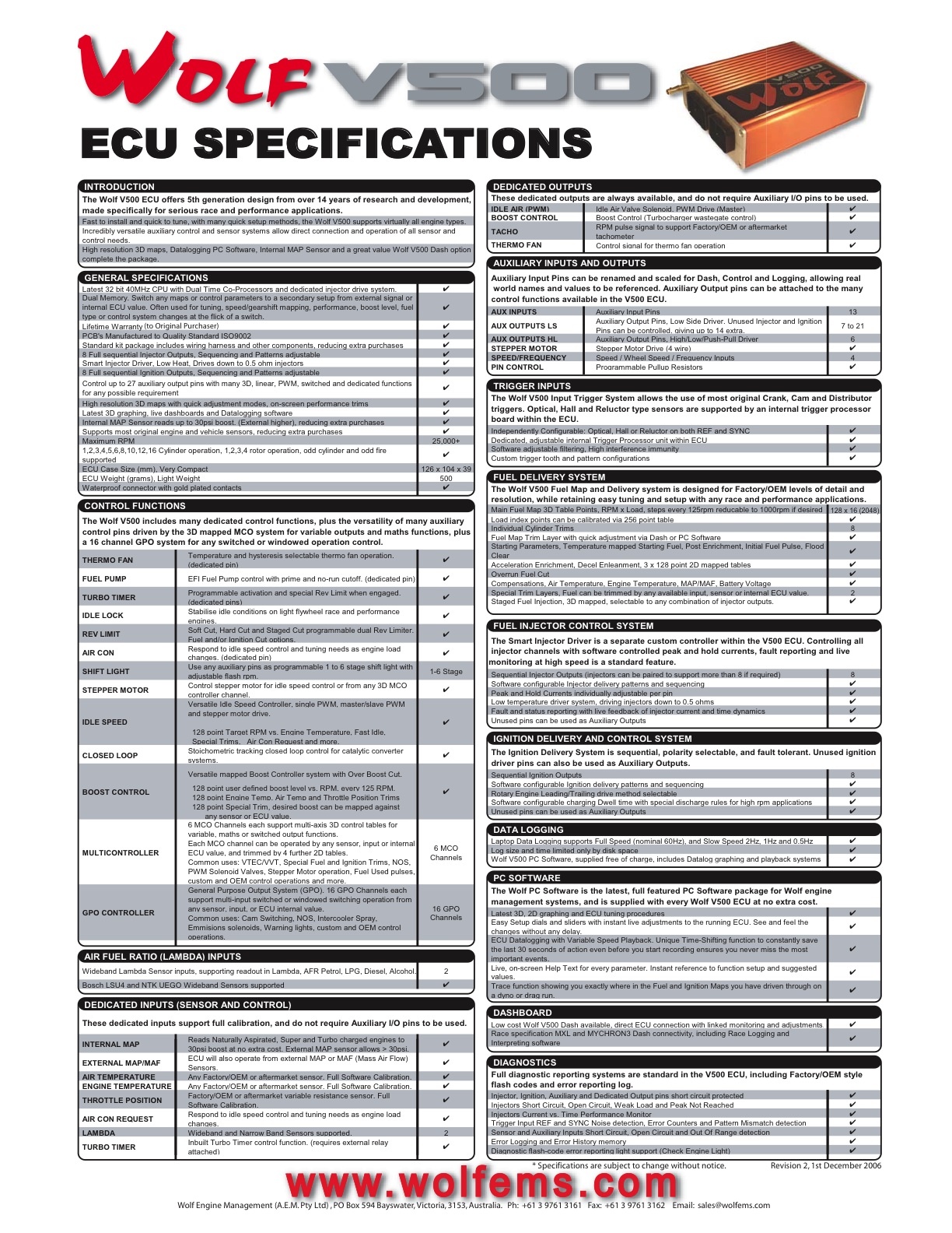
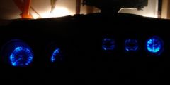
During my build, I swapped in a set of 280z gauges (I like the font face) and converted the lighting to LEDs. I am using 5000 mcd 40-50 degree blue LEDs. I used 6 for the tach and speedo, and 4 each for the other 3 gauges. If interested, I will prepare a short write up about the conversion.
-
-
-
I am going to make this into a Word document myself, including photos, and then have it converted to a PDF at the office. Thank you for the offer though.
-
I would rather this thread stay on topic. I am hoping that they may sticky it. Saying that, Careless' question is valid and would be part of the installation.
-
I will also provide a discussion about setting up the Wolf system and my base start up map soon.
-
Supra 7MGTE injectors are low impedence.
-
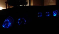
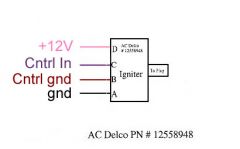
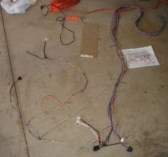
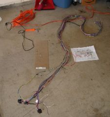
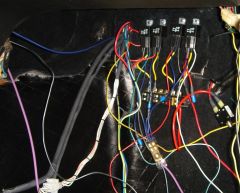
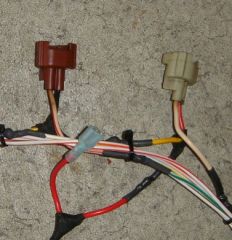
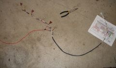
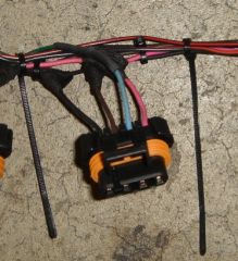
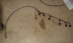
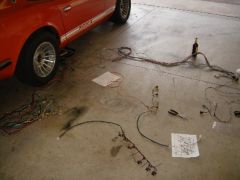
As stated, following is my installation guide for the Wolf V500 system. First off, I need to thank Ron Tyler for his outstanding support and understanding. He was always available to answer all of my questions, even those not pertaining to the Wolf V500. With that out of the way, onto the installation guide. The Wolf V500 system is an outstanding engine management system. Ron is a much better source of information, but I will endeavor to provide a summary of the highlights. The Wolf V500 system is capable of handling sequential injection and ignition for up to 8 cylinders, or batch injection and ignition for up to 16 cylinders. It has boost control, fuel pump control, fan control, internal 3 bar MAP sensor (30 psi), external MAP sensor inputs, etc. More information is available at www.wolfems.com. At the bottom of this post is the specification sheet available from the website. Fuel injection control is achieved by setting and adjusting the fuel injector opening times for a given load and RPM. No more VE and AFR tables. Ignition control is similar. Both injection and ignition control have numerous modifiers (trims) that can be used to adjust each based on intake air temperature, manifold pressure, throttle position, engine temperature, battery voltage, acceleration, deceleration, etc. My installation write-up is geared for my specific build. However, the wiring diagram and Wolf inputs are the same regardless of the build. It is up to you to determine the correct inputs. DISCLAIMER (borrowed from Afshin): First, electrical shorts can burn out your EFI and/or cause a car fire. I have no interest in anyone doing this and don’t know if it will work for you or not. I have no formal training and am only sharing what I did for myself. There is no guarantee nor should any inference whatsoever be made that anything posted below is correct or safe. Cliff Notes: If you done blown up yourself, look in the mirror for liability. Now, onto the meaty part. The main components of my build consist of the following: 1983 280zxt engine Six (6) LS-1 Coil-on-plugs Supra 7MGTE 440cc injectors (low impedence) Garrett T03/04E 0.63 A/R 50 trim turbo Walbro GSL 392 fuel pump Flex-a-lite 210 fan 240sx TPS (potentiometer style) 1983 280zxt distributor Wolf V500 EMS I am utilizing the internal 3 bar MAP sensor in the Wolf ECU to measure my intake manifold pressure. Wolf also utilizes an engine temperature sensor (not cylinder head temperature sender, though I am going to do some testing) and intake air temperature sensor. I installed the engine temperature sensor is located in the lower thermostat housing where the thermotime switch is normally located. I installed intake air temperature in the pipe running from the intercooler to the throttle body, as close to the throttle body as possible. When you open the box, you are faced with a rats nest of wires that are connected to two large plugs. Rest assured, if I can do this, so can you. While it may look daunting, it is not that bad. Many of the wires are used for auxiliary inputs/outputs and are not used. For you Texans, that is a bottle of Shiner Bock in the picture below. Here is the wiring diagram for the Wolf V500 Power Distribution First thing is first. Our cars are over 30 years old and much of the wiring, while still in decent shape, is not up to the task of handling high current loads. All of your systems should be run off of new wires connected that draw their power from relays. Furthermore, you need to think about how are you going to distribute the power from a source to the relays, and then from the relays to the various components. You do not want to burn your car down, nor do you want to fry anything after you spend your time and money wiring everything up. Therefore, think through the entire build first, plan it out, and then execute. I setup my power distribution system as follows. I ran a 10 gage wire from the positive terminal of the battery to a 50 amp manually resetting circuit breaker. From the circuit breaker I ran a 10 gage wire to a new fuse block. From the fuse block I ran a power wire to the various relays controlling my components. The Wolf ECU is on its own circuit, relay and fuse. That way, if the car stops running for whatever reason, you can quickly eliminate a potential source of the problem. The electric fan is on its own circuit, relay and fuse as well, since it is a high draw (30 amp) component. The fuel pump shares a circuit with the distributor. The ignition coils and injectors also share a circuit. I tapped into the ignition wire (black/white) right after the ignition switch. I ran a new wire to a power distribution block, where four (4) wires then run to each relay. For those of you with a 240z, Ron Tyler informed me there is no single wire that is both hot in 'start' and hot in 'run'. You will need to replace the switch with a 280z switch that has a single wire that is hot in both 'start' and 'run'. Below is a good shot of my system. You can see the four relays above the fuse block, the circuit breaker to the right of the fuse block, and the ignition hot power distribution block below the fuse block. Yes, it's messy. I have not made an attempt to clean it up yet incase I need to trace down gremlins. The bundle of white wires with the connector at the lower left of the picture is my injector subharness connecting to the Wolf system. I am getting my vacuum reference from the intake manifold as shown below. It is the silver 90 degree fitting coming from the manifold. Fuel Injection Wolf controls the fuel injectors via six (6) inputs. Wolf switches ground for each injector depending on the injector sequence you set. The Supra 7MGTE injectors are rated at 440 cc/min and are not polarized. Wiring the injectors is straight-forward. Simply wire each input to the corresponding injector, and wire a common positive 12 volt supply to all of the injectors (the injectors are connected in series for the 12 volt supply). You can use either high impedence or low impedence injectors with Wolf. The system automatically compensates for either type. I made a separate harness for my injectors so that they are stand alone. I utilized a single 6 input connector for the Wolf inputs and a single insulated spade connector for the common power. This way, I can pull the fuel injector harness independently of the other systems. The following picture shows my fuel injector subharness. The bundle of white wires to the far right were part of the Wolf harness and correspond to the injector inputs. I installed the connector on the end of the white wires. This is where my injector subharness connects to the injector inputs coming from Wolf. The single red wire is my +12 volt power to the injectors. In this picture, you can see that the power wire for the injectors is shared between injectors. Ignition Like the fuel injectors, Wolf controls the ignition coils via six (6) inputs. Wolf sends a control signal for each coil depending on the firing sequence you set. The LS-1 coil-on-plugs have four (4) outputs as shown below. Wiring the coils is straight-forward as well. Simply wire each input to the corresponding coil, wire a common positive 12 volt supply to all of the coils (the injectors are connected in series for the 12 volt supply), and wire each ground as a ommon system as well. You have a decision at this point prior to wiring. You can wire up the coils in any order you chose. You can wire up the coils in the same order as the cylinders (1,2,3,4,5,6), in the firing order (1,5,3,6,2,4 for an L-series), etc. For simplicity and to keep things straight in my mind, I wired them up in the same order as the cylinders. Just as with the fuel injectors, I made a separate harness for my coils so that they are stand alone. I utilized a single 6 input connector for the Wolf inputs and a single insulated spade connector for the common power and the two common grounds (for a total of 4 connectors – 1 6 input connector and 3 insulated spade connectors). This way, I can pull the fuel injector harness independently of the other systems. The +12 volts comes from a dedicated relay that controls the injectors and coils. One of the grounds connects directly to the battery and the other ground connects to the same ground as the Wolf system. Here you can see my ignition coil subharness. A shot of the LS1 coil-on-plug plug. Pink is power, the two on the left are grounds, and the light blue is the signal. All of the plugs have the same color for 3 of the 4 wires. Only the signal wire changes color. Here is the pinout for the LS1 coil-on-plug. Here is a picture of the an LS1 coil as mounted on my car. Intake Air Temperature Sensor The IAT sensor connects to the Wolf system via two (2) wires. The sensor is not polarized. Simply wire the sensor to the Wolf ecu as indicated in the wiring diagram. You will need to input the calibration curve for your specific IAT sensor into Wolf. Engine Temperature Sensor The ET sensor connects to the Wolf system via two (2) wires. The sensor is not polarized. Simply wire the sensor to the Wolf system as indicated in the wiring diagram. You will need to input the calibration curve for your specific ET sensor into Wolf. You can see the sensor plug immediately below the upper radiator hose. Throttle Position Sensor The TPS connectors to Wolf via three (3) wires. Wolf requires a potentiometer style TPS such as that from a 240sx automatic. The TPS has three wires: a ground (black), power (red) and signal (white). Wolf has three inputs for the TPS as well (ground, power and signal). Thus, wiring up the TPS is rather simple. The picture below shows the TPS plug I wired. Once the engine is running, you will need to calibrate the TPS and Wolf. This is very easy to do. Simply measure the signal voltage (white wire) of the TPS in the idle position and write it down; measure the signal voltage at WOT and write it down. Input these two values in the TPS calibration drop box in Wolf. Viola’, you are now calibrated. Trigger Signal This is the single most input step in the entire process. The wiring diagram shows the Wolf input in a shielded cable. Wolf provides a small length of shielded cable, but chances are you will have to run additional length. THIS IS IMPORTANT. Do not skimp on the shielded cable. Noise in the line will cause numerous problems such bad timing, etc. I made my own shielded cable as the electronics store I frequent did not have a shielded cable with just three (3) 16 or 18 gage wires. I bought a sheathed 3 wire cable and some very nice steel braiding. I slipped the steel braiding over the cable and used heat shrink. Presto, a shielded cable. As indicated above, I am using the 280zxt distributor to provide my trigger reference. Ron Tyler drilled a small hole next to the slot that is for cylinder #1 on the optical disk. That is the reference for cylinder #1. The 280zxt has four (4) wires: black, white, red and green. Wolf only requires three (3) inputs: black, white and red. The green wire from the distributor is not used. The black wire is ground, the white is the trigger reference signal, and the red wire is for a +5 volt source that Wolf normally supplies. However, Ron Tyler recommended that the power source should be +12 volt. This does not damage the distributor and it provides an added level of insurance against noise in the line. I wired a three connector shielded plug to the stock sheathed cable on the distributor. The other end of the plug was wired to the shielded cable I made. This way I can disconnect the distributor from the shielded cable and pull it separately. The black and white wire connect to the Wolf supplied shielded cable; the red (power) wire is connected to a relay that it shares with the Wolf system. IMPORTANT. Pin A30 as shown in the wiring diagram is incorrect. The trigger reference signal should connect to Pin A28. Below is a picture of the shielded trigger reference plug. If you opt for the same trigger reference as I, then you'll probably want to modify your distributor cap. I simply cut the top off and superglued a piece of 26 gauge steel to the top. Paint with Kyrlon fusion semi-gloss black and you have one slick distributor cover. Fuel Pump Wiring the fuel pump to Wolf is rather simple. I used a relay to provide power to the pump. Wolf controls the fuel pump via the relay ground. Electric Fan As with the fuel pump, wiring up the electric fan to Wolf is simple. Again, I used a dedicated relay to provide power to the fan as it is a high draw device. Wolf controls the electric fan via the relay ground. I hope that you have found this to be useful. I will be adding to this write-up over the coming week, but I believe this to be a good foundation.

-
-

-
-
-
-
-
-
-
-
-
-
buzy, I was thinking of doing this exact modification to my 240z. Good to see that it looks halfway decent. I've also thought about doing a similiar treatement to the 'cowl' part of the hood, along the raised sides. I would leave the front "V" alone and only perforate the two sides. I need to find a spare hood though.
-
Are you sure you have the correct throwout collar length? I have a Fidanza flywheel, ACT clutch and pressure plate in my 240z and I have no problems.
-
Chuck, I had the fortune of probably buying one of the last Nissan head gaskets in the country about 4 months ago. I had to call around to 5 shops and the last place did a computer search for me and located one. I immediately hung up and called the place that had the gasket with the part number and had them ship it to me. It is currently sitting in my garage. Ishino is a good gasket maker as well. I bought two (2) of their intake/exhaust manifold gaskets. They looked EXACTLY like the Nissan gasket that I removed. No need for Permatex copper for the install. I would suggest calling a shop (Courtesy would do this for you) and ask them to do a parts search around the country. There is bound to be a place that has one in their inventory. I also got lucky with a local Nissan shop that had only ONE more remaining OE rear main seal (the circular one). The seal MSA sells is sh** compared to the OE seal.
-
Very slick.
-
Upgraded To 240SX Throttle Body & Gotta Question...
ktm replied to tommyboy's topic in Nissan L6 Forum
Actually, the automatic KA TPS has both the rheostat and the 2 switch functions. -
"when I turn the key I get a fast clicking sound that I think might be coming from the injectors" That is symptomatic of a bad solenoid.