

MONZTER
-
Posts
821 -
Joined
-
Last visited
-
Days Won
22
Content Type
Profiles
Forums
Blogs
Events
Gallery
Downloads
Store
Everything posted by MONZTER
-
-
-
-
-
-
That looks great Tim, The end tank shape looks like the ones I modeled from looking at the Treadstone. They worked waaaay better than the square Spearco ones in the standard CFD test. I also like your idea for the fencing. is the intercooler that close to the radiator or is there some plates or rubber seals that hooks to the fencing? Also do you have the front fencing extend to the inlet above or below the bumper as in one big ducted system. I experimented with completely enclosing the gap between the intercooler and the radiator, so basically the only air the radiator could get was through the intercooler. The car overheated immediately, Oh well
-
No Problem Tim, Hey, I have never seen pictures of your intercooler set up. I know I have looked at your engine set-up for inspiration, but never recall the intercooler. Do you have anything to show? or specs, like inlet outlet size, core size, flow direction. I want to know what helps 600+ HP obtainable with no detonation:lol:
-
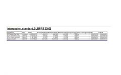
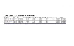
Hi Tim, Ya I guess you are right about the pressure drop thing and flow. Let me explain how I did the test. I let the boundary condition for the inlet simply be ambient pressure (around 14.7) and told the outlet boundary condition to be 25â€. I was trying to simulate flow as if on a flowbench. The new baffled design had better flow and the pressure drop was higher because of this. So I went back and re-ran both test. This time for the inlet boundary condition I gave it a volume flow of 392CFM (amount of flow pulled on the first test standard design) and the outlet a boundary condition of ambient ( so this is like if you blew 392 CFM of air in and just let the outlet be open. Look at the pressure drop now. The pressure drop for the standard original design stayed the same, as the flow was at the same, but look at how much the pressure drop decreased on the new baffled design. What do you think about this test? Does it make more sense for checking pressure drop for a given design?
-
-
-
"Thats a whole nother story" I cant jack my own thread. Check out my gallery
-
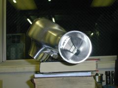
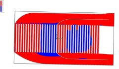
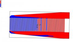
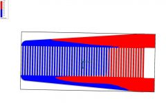
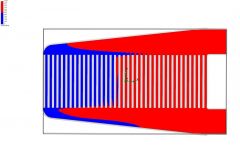
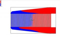
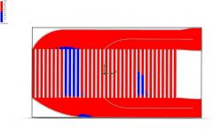
Some people have asked about the flow characteristics of some of the intercoolers that are being used a lot, mostly the Treadstone ones. So I made some quick models from pictures I saw (so, no the results are not totally accurate, just for the concept and comparison. Remember there are no turbulators in the tubes so the pressures will be different and the flow results may be different.) here are some quick test. From what I can tell the cast endtanks that blend smoothly into the inlet and outlets are a big plus. I would stay away from the square edge cut and weld like I bought. The sharp corner on the cut and weld ones seem to be contributing to the recirculation flow, the smooth cast tanks do seem to have a problem. Again this is only from my rough testing, don’t take this as a rule. So I wanted to look at core sizing, and the fact that everybody runs huge intecoolers rated for 1200-1400 CFM when there only pushing 700 – which is good for probably 450hp. I am showing below the following: 793 CFM 550hp flow 20psi boost. The plot is velocity from 0-1000 inches per second and I am only showing the range above and below this to help identify where the flow is going. From the picture you can see how little of the core is actually being used. I am not saying air is not flowing, it’s just going way slower than the front half. Click on the pics to enlarge" My modified version 6x18.5x3.5 Treadstone 6x18.5x3.5 Treadstone 6x25x3.5 Now same test at ridiculous flow 1200 CFM for both 18.5 long cores and 1492 for the 25†core (what the max flow is rated at) You can see better use of the core and more uniform velocity when the flow is closer to its suggested rating. So what does this mean? My best guess is that we are using intercoolers that are bigger than necessary. What is bad about this - I would like to know your opinions about intercoolers that are way bigger than the flow they need. What are the plusses and what are the minuses?
-
-
-
-
-
-
-
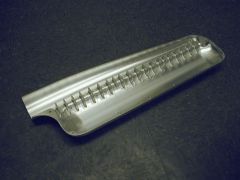
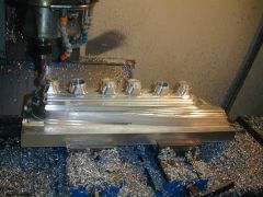
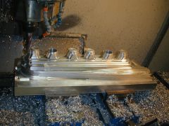
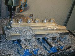
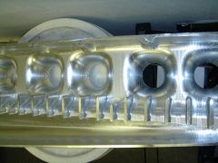
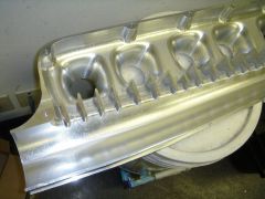
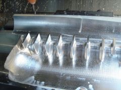
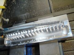
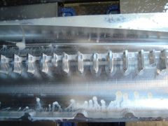
Some more pics of the inside cover and details of the airhorns, dividers
-
-
-
-
-
-
Me too, Thats where I got the idea from. Good book. most of my parts I have been building are based on the "ideal" concepts from that book
