

MONZTER
-
Posts
832 -
Joined
-
Last visited
-
Days Won
33
Content Type
Profiles
Forums
Blogs
Events
Gallery
Downloads
Store
Everything posted by MONZTER
-
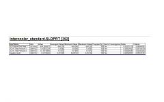
Hi Tim, Ya I guess you are right about the pressure drop thing and flow. Let me explain how I did the test. I let the boundary condition for the inlet simply be ambient pressure (around 14.7) and told the outlet boundary condition to be 25â€. I was trying to simulate flow as if on a flowbench. The new baffled design had better flow and the pressure drop was higher because of this. So I went back and re-ran both test. This time for the inlet boundary condition I gave it a volume flow of 392CFM (amount of flow pulled on the first test standard design) and the outlet a boundary condition of ambient ( so this is like if you blew 392 CFM of air in and just let the outlet be open. Look at the pressure drop now. The pressure drop for the standard original design stayed the same, as the flow was at the same, but look at how much the pressure drop decreased on the new baffled design. What do you think about this test? Does it make more sense for checking pressure drop for a given design?
-
-

-
"Thats a whole nother story" I cant jack my own thread. Check out my gallery
-
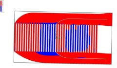
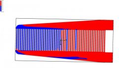
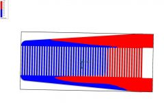
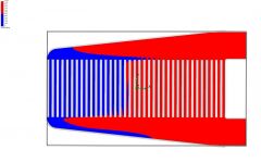
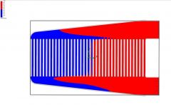
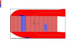
Some people have asked about the flow characteristics of some of the intercoolers that are being used a lot, mostly the Treadstone ones. So I made some quick models from pictures I saw (so, no the results are not totally accurate, just for the concept and comparison. Remember there are no turbulators in the tubes so the pressures will be different and the flow results may be different.) here are some quick test. From what I can tell the cast endtanks that blend smoothly into the inlet and outlets are a big plus. I would stay away from the square edge cut and weld like I bought. The sharp corner on the cut and weld ones seem to be contributing to the recirculation flow, the smooth cast tanks do seem to have a problem. Again this is only from my rough testing, don’t take this as a rule. So I wanted to look at core sizing, and the fact that everybody runs huge intecoolers rated for 1200-1400 CFM when there only pushing 700 – which is good for probably 450hp. I am showing below the following: 793 CFM 550hp flow 20psi boost. The plot is velocity from 0-1000 inches per second and I am only showing the range above and below this to help identify where the flow is going. From the picture you can see how little of the core is actually being used. I am not saying air is not flowing, it’s just going way slower than the front half. Click on the pics to enlarge" My modified version 6x18.5x3.5 Treadstone 6x18.5x3.5 Treadstone 6x25x3.5 Now same test at ridiculous flow 1200 CFM for both 18.5 long cores and 1492 for the 25†core (what the max flow is rated at) You can see better use of the core and more uniform velocity when the flow is closer to its suggested rating. So what does this mean? My best guess is that we are using intercoolers that are bigger than necessary. What is bad about this - I would like to know your opinions about intercoolers that are way bigger than the flow they need. What are the plusses and what are the minuses?
-
-
-
-
-
-
-
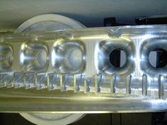
Some more pics of the inside cover and details of the airhorns, dividers
-
-
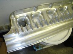
-
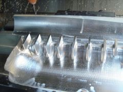
-
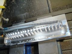
-
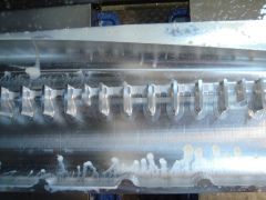
-
Me too, Thats where I got the idea from. Good book. most of my parts I have been building are based on the "ideal" concepts from that book
-
A bunch of good post and questions. The purpose of my initial test was to see if I could make the intercooler I already purchased better. I think I succeeded. If I had to do it again, I would not buy the same set-up and modify it. I would go for a completely different tank design that doesn’t flow the air perpendicular across the core in the first place. Have you guys ever seen this site? http://www.gurneyflap.com/bmwturbof1engine.html Some of the old F-1 cars are great inspiration
-
I love this video and the sound of that straight 6 http://video.search.yahoo.com/video/play?p=2005_gemenos_castellana&ei=UTF-8&fr=yfp-t-501&tnr=21&vid=1097229480
-
Thanks Ron, Even better is that my old Datsun still has the original paint and rust. It makes it that much more fun not having to worry about some pretty paint.
-
For just the reason stated by Zguy36 above. I thought a bigger taper in the bottom would help even out the flow in the second half of the core and eliminate any dead spots. I knew what direction the air was flowing so I figured a little more room on top would keep the velocity more consistent. I think most intercoolers are symmetrical because they are universal fit and you can then run the air in any direction you want.
-
Yep I am getting some turbulence in the dead spot where the first and second halves of the core are separated. I will post a close up of that section so you can see it better soon. It’s not perfect, but as you said a lot better than what it was, and I will have to be just happy with that. I actually have plans to make my own tanks from scratch for my next build, and they will eliminate this problem, I just wanted to salvage the intercooler I already bought. I bought it in the first place because I am getting tired of my car never being finished, and I thought I would save some time by having one built. Well after getting it I couldn’t just leave well enough alone.
-
The software is Cosmos Floworks, I think it’s at its limits with the narrow fluid space in the core. The company I work for just bought CD-Adaptco Star CCM+ and Star Pro-E for our external flow models, seems much more capable as it is the same software used by the F-1 teams. I will re-do some of these test with the new software after I get some training. http://www.cd-adapco.com/products/STAR-CCM_plus/index.html
-
It seems like there has been alot of talk about the pluses and minuses of the different intercooler configurations for our Z cars. Which is better? Same side inlet and outlet, or opposite side? That’s for another post that has been debated over and over. What I wanted to show was my decision, and what I have found out, and how I have modified it to make what I think is a good solution to an efficient design. My decision was to go with the inlet and outlet on the same side, as I really wanted the shortest possible tubing, not to mention what I believe to be a intercooler with less pressure drop. So I ordered up a Custom sheet metal tank Spearco unit 18x6x3.5 , only to be really disappointed when it showed up, as I have seen better looking agriculture equipment. The inlet and outlet were just butt welded on with no regard to smooth airflow, and the ends were cut nearly square, again not really smooth creative work. Here is a pictures of the stock unit as delivered from Spearco. We have all heard talk of how this type of intercooler recycles the air inside, in a circular motion near the inlet and outlet. Also, it is known as not being very efficient to cooling, because all the air gets pushed to the end of the tank, not letting the air flow evenly through the core. So I modeled it up in Pro-E and set to work doing some CFD flow testing on it for a little look. The test was done very simply, ambient on the inlet side and 25" on the outlet side. I wanted to test total CFM flow as well as pressure drop and distribution of the air. Please keep in mind this is only a quick test and the core is correct in dimensions, but obviously no tubulators, So look at the info for what it is, a comparison between one test and another, not between this test and a actual unit. So you can see in this picture first off is a recirculation effect. The air enters in the bottom inlet, up through the core, out, back down the core, back up the core... click to enlarge the picture and look at the flow arrows. Next is the pressure plot- Finally the velocity plot. So now on to the modifications. First off is the inlet and outlet. I made nice square to round transitions 2.5" inlet and 3" outlet. No longer is there a sharp square edge right before the outlet, you can see the effect on the pressure plot above. Next, I made smoother tapering sections at the end of the plenum. Finally, I made divider plates to basically split the Plenum into two halves, hopefully improving the balance of flow, fixing the recirculation problem, increasing the heat rejection and thus efficiency. Check out the arrows - no more recirculation Pressure plot shows the air is being distributed more evenly through the full core, not just he ends. The smooth inlet and outlet also show the lack of a high pressure flow reducing area right before the outlet. Check out the velocity. The air seems to stay more consistent in speed, I assume this is why there is a little more pressure drop. Check out the numbers. An increase of 162CFM through the same core. So what do you think? Does it look like it all makes sense? Jeff