

MONZTER
-
Posts
826 -
Joined
-
Last visited
-
Days Won
26
Content Type
Profiles
Forums
Blogs
Events
Gallery
Downloads
Store
Everything posted by MONZTER
-
-
-
-
-
-
-
-
-
-
-
-
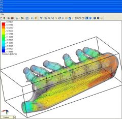
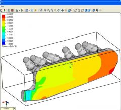
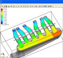
Tony, Your 100% correct. The TWM spacing I used is standard mounting for all the universal manifolds out there. So really this thing could bolt up to any throttle body mounted to and triple style manifold. I should be getting some CFD results soon; we'll se how it looks. Jeff
-
I'm not sure yet. The first one will be CNC machined in to halves and then welded together for testing. I am designing it with casting in mind. The first one is going to be pretty expensive, as it will be out of a big chunk of metal. If I cast them, I would probably make the casting patterns off the CNC prototype. I guess I will have to look into the expense for casting them. I dont know how many people would want a turbo manifold designed to work only with TWM throttle bodies. Thanks Jeff
-
-
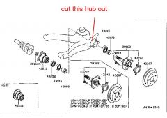
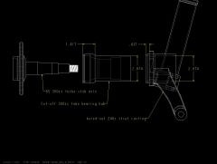
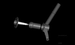
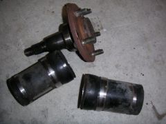
 Hey Guys, Don't know if this helps or not, but here is what I did to increase the offset and strength of the rear of my 240. I got some rear control arms from a 85 300zx turbo, stubs and companion flanges. The bearing hub on this arm is welded on to the control arm. I cut the bearing hub off and cleaned up the left over welds making the OD of the hub concentric with the ID. So now I have a perfect set of bearing hubs. Next I took my 240 strut and removed the strut tube from it leaving only the casting (so it will fit in my lathe). I chucked this up in the lath and cleaned the ID of the casting. The ID of the casting is now exactly the correct size of the OD for the 300ZX hub. I then pressed fit the hub into the 240 strut casting and then welded around it with 309 stainless. So now the 240 strut uses 300zx turbo stub axle, bearings, companion flanges, CV axles and my offset is +20 mm to work perfectly with 40 offset wheels and no spacers. I hope this make sense? Here are some pictures, and some numbers. Click on the pictures to go to my gallery for more more and bigger views. Jeff
 -
-
-
-
I got all my parts from Motorsport Auto (MSA) Sal ordered them for me. He had a hard time finding the inner pinion bearing. I would not do it again, don’t think I gained anything from doing it except learning what a pain in the #$%$^ it was. I was installing a Quaiffe which doesn’t fit back into the diff housing with the side bearings installed. You have to press them on through the side holes. You then check the pinion height to find out it needs adjustment, how do you get the side bearings back off to remove the diff and get the pinion back out to shim it? Many hours of work that’s how. I had to make a special puller. Learn from our mistakes, don’t fix what ain’t broke. Good Luck
-
It IS in the Factory Service Manual FSM Thats what I used
-
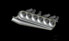
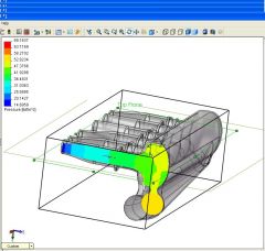
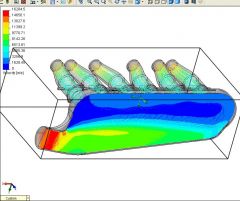
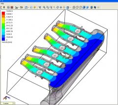
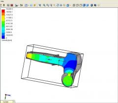
Well good news, A very generous person on this forum has agreed to do some CFD on this plenum design. I also met with my machinist friend, and priced out the material. He said I could run the part on his brand new Fadal 60x30 CNC. This is great news and it seems like it is going to be a go for me to build one and test it out. Thanks Jeff
-
I measured the worm gear on the main shaft for both the 71B and 71C that drives the spedo. Both were the same size. The 71C was plastic and the 71B metal. Both interchanged.
-
look at the micro fische for the 85 or earlier 71c box from a 300zx, the syncro rings were different and sound like what your talking about http://carfiche.com/manuals022/cars/
-
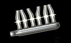
Similar to what I had planned, but I was going to tack weld it together for testing on a flow bench, and then weld it up when happy with the results. You can see inthe cut away all the extra material I left in the slot area so it can be made wider if it needed to be. I am trying to figure out how to measure the pressure loss problem with out the software??
-
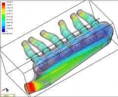
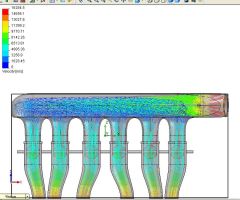
Thanks for the link Dave, good reading. Very depressing reading actually. I do not have access to the CFD, so it sounds like it would be impossible to get the right configuration with out the software. My design so far is just based on what I have seen and read. I have very little to no experience in fluid dynamics, and I would hate to build this manifold to have it be worse than a simple open plenum design. HMMM what to do, risk it and make one - possible wasting the time and money, or go with what we know and make something like a plenum used on the RB motors. I hate problems like this when my hands are tied by my limited resources. Making it is the easy part for me. I don't think common sense will work on this project. Thanks Jeff