-
Posts
1193 -
Joined
-
Last visited
-
Days Won
30
Content Type
Profiles
Forums
Blogs
Events
Gallery
Downloads
Store
Everything posted by 74_5.0L_Z
-
I made my own. I don't know of any off-the-shelf long tube headers that will work for our Ford Powered Z cars. http://forums.hybridz.org/topic/114643-my-custom-made-headers-and-exhaust-system/
-

Will the Laine Family sbf write-up work for a 351W?
74_5.0L_Z replied to amuscato77's topic in Ford V8Z Tech Board
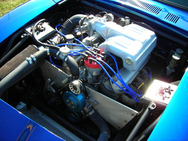
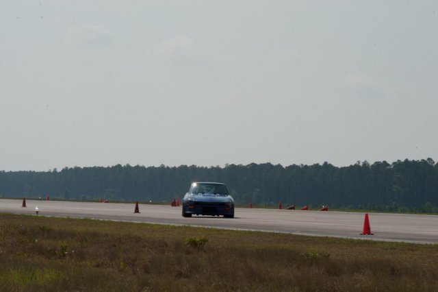
The main difference will be that the 351W is taller and wider and weighs ~75 pounds more. I have had considerable experience with both engines. My 1970 Mustang Fastback started life with a 302 and a C4 automatic. I had this car when I was young (1987) and the first thing that I did to the 302 was to add headers and exhaust. Shortly after the headers and exhaust, the 302 died. Luckily I had a 351W ready to go. For the most part, the 351W was a direct bolt in replacement for the 302. I reused the same motor mounts, and was able to reuse the headers. However, because the 351W is taller and wider, the exhaust needed to be modified. The H-pipe had to be cut-out and a longer piece welded in, and the exhaust was now 3/4" higher from the ground. Luckily the exhaust had been a little low with the 302 installed, so I got lucky. An additional problem that I had was clearance between the air cleaner and hood after installing the 351W. I ended up with a low profile air cleaner to clear the hood. There are people who have installed the 351W in the S30 Z cars. I don't know how they mounted them. I personally have a 5.0L (302) that is stroked to 327 cubic inches installed in my car. I like the 351W. It is capable of making much more horsepower with its stock block than the late model 5.0L engines. However, I like the 302 because it is compact and light. I autocross my car and I don't need a million horsepower. My engine is mounted using a front plate / mid plate set-up, and if this is not going to be a street car, I highly recommend using this method to mount the engine. It creates tons of space to route headers. -

Will the Laine Family sbf write-up work for a 351W?
74_5.0L_Z replied to amuscato77's topic in Ford V8Z Tech Board
There is much similarity between the 289, 302, and 351 engines. However, the block is not one of them. The 351W has a taller deck height (9.5" vs 8.2") . As such, the 351W is taller, wider, and heavier. The 351W also has different size main bearing journals and longer connecting rods. What the 351W shares with the other Windsor engines is bore spacing, bell-housing bolt pattern, head bolt pattern, and motor mount bolt pattern. The heads are interchangeable between the various Windsor engines, but you cannot interchange the intake manifold between the 351W and its smaller cousins. There is enough similarity between the engines that the Laine Family write-up will be extremely useful. -
http://forums.hybridz.org/topic/83751-how-much-tubing-to-make-a-roll-bar/
-
How unfortunate about the loss of recent posts. I'll bet we lost at least a hundred useless "What tire size", "What backspacing", and "What Color should I paint this" topics. We need a sub-forum for useless, non-technical crap to go in.
-
I have been battling a similar lack of rear traction on corner exit. This year in response to that problem I have done several things. First, I raised the front by 0.75" to raise my front roll center. That seemed to help, So I then began putting successively lighter springs in the rear. I began the year with 500 lb/in front and 450 lb/in rear and a 20mm front sway bar. I then switched the 450 lb/in rear for 425 lb/in. This change decreased my rear frequency, decreased the rear contribution to lateral load distribution, and also slight lowered my rear roll center. It was a noticeable improvement. Next, I replaced the 425 lb/in springs with 400 lb/in springs in the rear. Again, this made a noticeable improvement. However, again I changed several things by putting the lighter springs in the rear. Lower frequency, lower contribution to the lateral load distribution, and lower roll center. With the changes that I have made, I have made an extremely noticeable improvement to my corner exit traction. I have also not yet reached a push condition that can't be driven around. At the last autocross event, a friend captured video showing me lifting the inside front tire and carrying it for about ten feet. The car also now squats much more noticeably in the rear.
-
I have been getting the same errors.
-
The other thing that affects pedal effort is the relative size of the caliper piston area versus the master cylinder piston area. Contrary to what many people seem to think, reducing the size of the master cylinder piston lowers the required pedal effort and increases the pedal travel. Increasing the master cylinder piston size increases the required pedal effort and reduces the pedal travel.
-
I deleted my booster about thirteen years ago when I went to four wheel disc brakes. All the it takes is a plate that has the master cylinder bolt pattern superimposed on the firewall bolt pattern, and an appropriate pushrod/clevis going into the master cylinder. I used the stock 260Z master cylinder with my set-up. I believe that it has a 15/16 bore. I autocross the car frequently, and I love the feel of my brakes. So, can you delete the booster? The answer is yes. Should you use a single circuit master cylinder like used on the kit shown by the original poster? Hell No! My entire brake system is as follows: Front: 11.75 x 1.2 vented rotors Outlaw 2800 calipers with 1.75" pistons Hawk HB237N.625 Pads (HP Plus compound) Rear: 10.75 x 0.81" vented rotors Outlaw 2800 calipers with 1.375" pistons Hawk HB237N.625 Pads Wilwood proportioning valve Stock Pedal Assembly Stock Master Cylinder With good components front and rear and good brake balance, there is no need for a brake booster on our cars (IMHO). To me, the booster is only an extra source of weight and an extra item that can fail. The pictures below show the aluminum plate that I used to delete the booster. The first picture shows the plate on the firewall, and the second shows the master cylinder installed. Note: Edited my brake set-up inventory. I thought I had used the 1.25" pistons in the rear, but I was wrong. I installed the 1.375 pistons on the rear thirteen years ago. The memory just isn't what it used to be....
-
I just got back from there. My wife, daughter, and I had a great time. We did all of the touristy things while we were there, and we also did some hiking. Spend a whole day in Golden Gate Park if you can. Start at the museums and work your way to the beach. Eat at the Beach House. Hike the Lands End Trail. This is a cool hike with lots of cliffs. Go to Muir Woods. Get there early and take the Dipsea Trail instead of following the tourists (about 5 miles). You will have the place to yourself if you go against the grain.
-
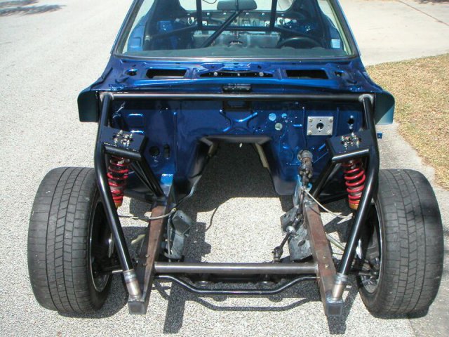
My fenders provide 1.5" of flare versus stock, and I have very little clearance between the tires and the coil-overs.
-
I run 15x10 on all four corners with Hoosier 275/35/15 tires. I am using Spinwerkes series 82 wheels with 5.25" backspace. I use .25" spacers on the fron to clear my coil-overs. I also have the SubtleZ fenders on the car for added clearance.
-
My second 260Z (the one made in 04/74) has VIN RLS30-27435, so I think you can be assured that your car is an early 260Z and has the 240Z style rear strut towers.
-
If you have an early 260Z, then it will have the same strut towers as the 240Z. I am not sure on the cut-off number where the chassis began to resemble the 280Z (large bumpers and raised rear strut towers). I do know that both of the 260Zs that I have owned are the early style, and I have mixed and matched interior pieces that I used from a 240Z. The first 260Z that I owned was manufactured in 08/73 (RLS30-000481) and the current 260Z that I own was manufactured in 04/74. Both cars have more in common with the 1973 240Z than they do with the 1975 280Z. Neither has the big bumpers and neither has the raised strut towers.
-
I got the best suspension deal of my life from a guy who drove his car without getting it aligned first. He had just spent two years building a beautiful 1969 Cougar Eliminator. He painted it and replaced every single suspension component with new parts (upper and lower control arms, springs, steering box, center link, idler arm, power steering, ball joints, tie rods, and disk brakes). He did a quick tape measure alignment on it and took it for a drive. Within a day, he wrapped it around a telephone pole when he lost control in a turn (not even pushing the car). Obviously, he hadn't done as good an alignment job as he thought with the tape measure. Fortunately, I was in the market for new suspension for my 1970 Mustang Mach 1. I bought all of his new components for $200.00 (this was in 1987). A good day for me, not so much for him.
-

Right front wheel hub failure at autocross
74_5.0L_Z replied to wheelman's topic in Brakes, Wheels, Suspension and Chassis
Maybe it's just the photos, but it looks like the mounting faces of your wheel and hub were not mating flat and flush. The area on the wheel at the inner bore and the area of the hub adjacent to the bearing housing are both shiny as if you had a very narrow area of contact. If this is true, then when you were torquing the wheel you were also putting the ears of the hub in bending. It may just be the pictures though. -

Right front wheel hub failure at autocross
74_5.0L_Z replied to wheelman's topic in Brakes, Wheels, Suspension and Chassis
Wow! Have you inspected the other side for the beginning signs of cracks? It may be possible to find some evidence on the other hub as to where the cracks are starting. -

Right front wheel hub failure at autocross
74_5.0L_Z replied to wheelman's topic in Brakes, Wheels, Suspension and Chassis
I am very interested to see the pictures of the failed hub for several reasons: I am running 275/35/15 Hoosier A6 wheels on 10 inch wheels (like you). I have the 4-lug hubs (like you). I am running about 400 rwhp (like you). I don't want my wheel to pass me on track (unlike you). I hope you didn't mess the car up very much. -

T5 gearbox for circuit laps?
74_5.0L_Z replied to 260DET's topic in Gen III & IV Chevy V8Z Tech Board
There are two companies in the US that make upgrade kits for the T5. The two companies (Astro Performance and G-Force) advertise 500+ hp capability for their products. I know of several people running the G-Force in the American Iron racing series with success. I personally have an upgraded T5 from G-Force, but I only use my car for autocross. I am making 400hp/ 400 ft-lbs of torque at the wheels. Additionally, G-Force has a variety of gear choices and the choice of dog-ring or synchomesh. -
Ah, I see. I'm obviously not LS savvy. I am still in the dark ages with my Windsor based Ford. Carry on...
-
Jon, You are essentially building a race car. Why are you not using a front plate / mid-plate to mount the engine? I love mine. The front plate essentially ties the strut towers together and helps stiffen the chassis, and the lack of the motor mounts on the side of the block creates a bunch of space for headers.
-

Chassis Setup (corner weights)
74_5.0L_Z replied to 74_5.0L_Z's topic in Brakes, Wheels, Suspension and Chassis
Jon is sending me some steering arms so that I can make the measurements. However, I think it would be a good idea for at least two people to make independent measurements to help catch mistakes. I will put together a figure and post it tomorrow to show the exact dimensions that I need. I am trying to put together an accurate model of the complete suspension so that I can see the interaction of caster, camber, SAI, pin offset, etc. There are changes that I want to make, but it is silly to make changes until you know exactly what you have so that you can determine what you want to change, and why. -

Chassis Setup (corner weights)
74_5.0L_Z replied to 74_5.0L_Z's topic in Brakes, Wheels, Suspension and Chassis
Clarkspeed said,"I run a little higher front RC (I hope you measured to the ball joint center!)." That brings up a good point. I have had to estimate the position of the ball joint center. I know that it is offset rearward and inboard from the center of the strut axis. The inboard offset has the effect of raising the roll center, and the rearward offset provides mechanical trail. I can do the math to establish the relationship between the strut axis and the steering axis if someone has GOOD measurement of the ball joint center position relative to the strut. Anyone? If nobody has these dimensions, I can make the measurements myself. I have a spare strut and a ball joint that I have cut apart (to extract the ball), but I do not have a spare steering arm to complete the assembly. If someone can lend me one, I will be happy to take the necessary measurements and create a cad model of the front strut and ball joint. I would also publish the results for everyone to use. -

Chassis Setup (corner weights)
74_5.0L_Z replied to 74_5.0L_Z's topic in Brakes, Wheels, Suspension and Chassis
I really only use the car for autocross though I hope to start doing track events soon. I have the rear about as low as I can get it without rubbing the tire on the inside of my SubtleZ rear quarters. I am doing my best to tune out the oversteer without adding ballast, but I will if I have to. I plan to install the new rear springs before the next event, and I will also have some ballast that I can add if required. I am trying to decide where to add the weight. The easiest place will be on the floor behind the passenger seat. Or if I am a little creative, I could add it between the differential and fuel cell.


