
74_5.0L_Z
-
Posts
1194 -
Joined
-
Last visited
-
Days Won
30
Content Type
Profiles
Forums
Blogs
Events
Gallery
Downloads
Store
Everything posted by 74_5.0L_Z
-
When you put your hand over the carb you are choking the death out of it . As the piston goes down you are creating a heck of a vacuum at the carb and pulling in a bunch of fuel. After 3 or 4 pulls you have enough fuel in the exhaust to combust, and it goes boom. This would also suggest that the ignition is firing on the exhaust stroke, or late in the power stroke after the exhaust valve has begun to open.
-
My 260Z with 300+ rwhp and a 5.0L EFI motor gets about 21 mpg on the highway. My engine has the stock 1989 bottom end with a bazillion miles on it, has edlbrock aluminum heads, Crower 15511 cam, Cobra intake 24# injectors, 73mm MAF, Ford Motorsport 1.72:1 roller rockers(E351). The key to getting good milage is an overdrive transmission (T5), and reasonable gear ratio. I have the 3.545 gear now and will soon be running the 3.36. With the rear current gear ratio and 24.7" tall tires, the car runs at 2300 rpm at 70 mph in fifth gear(0.680:1). Without the overdrive, my rpms would be 3400 at 70 mph(ugh!). After I switch to the 3.36 rear gear, 70mph will be at 2200 rpms and 160mph will be at 5000 rpms in fifth:twisted: . Right now, with the 3.545 rear end, I never use 1st gear on the street. It is too short, and the torque of the 5.0L makes it very comfortable to take off in second gear. The 3.36 rear gear should make first gear more streetable.
-
What if we declare HybridZ a religion? Can we get tax breaks? Does that make SuperDan the pope(or head shaman)? JohnC, BlueOvalZ, Mikelly, etc... can be bishops. What do you think? Donations are being accepted to my Temple of Z:)
-
I love Fords, but I am slightly biased. I have owned the following: 1966 mustang fastback 1965 mustang coupe 1970 Mach 1 I currently drive a 1995 Ford Ranger (2.3L) that has never given me any problems even though I abuse it like an ugly step child. My wife currently drives a 2005 Mustang V6. Even though this is a V6 it runs very strong. Of course my favorite Ford is my 1974 5.0L powered 260Z. The engine came out of a wrecked 1989 highway patrol mustang with a bazillion miles on it. Since installing this engine 5+ years ago, I have never even looked at the bearings or rings. I have installed Edelbrock aluminum heads, a crower 15511 cam, FMS 1.72 roller lifters, Cobra intake, 24# injectors, 73mm MAF. The car has made ~75 1/4 mile passes (best of 12.42 @ 113), has made several hundred autocross runs, and has been driven several thousand miles without any engine related problems. Do I love my Fords? HELL YES:-D
-

Damaged Front Frame Rails Due To Sway Bar
74_5.0L_Z replied to texasz's topic in Brakes, Wheels, Suspension and Chassis
When I made my new front frame rails, I retained the stock sway bar mounting point. I want something a bit more resilient than the stock nut plate so here is what I did: I drilled 1/2" holes through the entire frame, then inserted a 1/2" OD (3/8" ID) tube through the frame and weld it flush on both sides. Then I inserted 3/8" Grade 8 bolts and washers all the way through the frame to hold the sway bar. You can just see the heads of the bolts in this picture. -
removing the rubber from the floor?
74_5.0L_Z replied to hat1324's topic in Brakes, Wheels, Suspension and Chassis
We discussed this at length in this thread: http://forums.hybridz.org/showthread.php?t=102881 -
Brake Pad Recommendation
74_5.0L_Z replied to Scottie-GNZ's topic in Brakes, Wheels, Suspension and Chassis
Scottie, On my buddy's superstock, we found that the cheap shoes held much better than the more expensive ones on the line. We still sometimes had trouble with the car creeping through the beams. We have since switched to a trans-brake. Didn't you use a trans-brake on the old Z? Nothing beats them for launching the car, but they are hard on parts. -
Bumpsteer spacers................
74_5.0L_Z replied to Vintage-TechZ's topic in Brakes, Wheels, Suspension and Chassis
I have been toying with the idea of building a front crossmember as described by TUBE80Z, and toying with anti-dive. When I relocated my LCA pivots up 3/4" and out 1/4", I also relocated the T/C pivots by the same amount. Unfortunately, I am near the limit for relocating the T/C upward without interfering with the frame. I wish that I had designed my front frame differently. If I were to do it again, I would have the frame rails below the LCA pivot until just forward of the crossmember. But alas.... -
I looked at the page that you referred to and sure enough it states the following for cars 2001-3500 lb: 1.750 x 0.120--------------mild steel 1501-2500 lb-------------1.625 x .095------Alloy Steel BTW, I have looked at the pictures of your cage. NICE WORK! Some of us are just anal about weight. My main hoop and other "required" tubes are 1.625 x 0.120 (4130). All of the optional tubing is either 1.625 x 0.083 or 1.625 x 0.065. If I had it to do again, I would have used 0.095 rather than 0.120 for my main hoop. One of my favorite things about this site is the way each of us arrive at different solutions to the same problem. I look forward to watching the progress on your car. Jon had a concern about using 1.5 x 0.120 and wall thickness. Section 18.1 allows for 0.010" below nominal thickness. So as long as you stay above .110 you're golden. Dan
-
I just looked at my SCCA GCR (2004) section 18.1. It states: Minimum tubing sizes for (all shoroom stock, Touring and Improved Touring Category automobiles registered after June 1, 1994) for all required cage elements (All dimensions in inches): Up to 1500 lbs--------------------1.375 x 0.095 DOM/Seamless/Alloy 1501 to 2200 lbs-----------------1.500 x 0.095 DOM/Seamless/Alloy 2201 to 3000 lbs-----------------1.500 x 0.120 DOM/Seamless/Alloy ------------------------------------1.625 x 0.120 DOM/Seamless/Alloy ------------------------------------1.750 x 0.095 DOM/Seamless/Alloy It also states that ERW is not allowed in any car registered with SCCA after01/01/2003. Weights are without driver and fuel.
-
Here is how I removed the stuff from the inside of my car: I used a wide metal scraper and a hair dryer. Simply put the scraper against a free edge of the material at a low angle of attack, and apply a little force. Simultaneously, heat the material just ahead of the scraper until it just begins to soften. As soon as the stuff starts to soften, the blade of the scraper will easily slide between the metal and the black goo. Using this method, I was able to remove all of the material from the inside of my car in about two hours. Things to remember: Keep the blade as flat as possible. Don't heat the stuff to a liquid. Just apply enough heat to soften it up. If you liquify it, you will have a gooey mess. After you are finished with the scraper, you will still have a light residue of the black tar. This will wipe off quite easily with mineral spirits. After you wipe it with mineral spirits, rewipe with a paint prep solvent, and you will be ready for paint. PS. This method also works for removing under coating.
-
Jon's 2 year roll cage saga...
74_5.0L_Z replied to JMortensen's topic in Brakes, Wheels, Suspension and Chassis
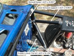
My strut bar and the two tubes connecting the main hoop to the strut bar are 1.625 x 0.083. The main hoop, the diagonal, and the bars from the top of the main hoop to the strut bar are 1.625 x 0.120. All of the tubing is 4130N (normalized chromoloy) and is TIG welded. My door bars are 1.625 x 0.120, the hoop at the firewall is 1.625 x 0.083, and most of the front end tubing is 1.625 x 0.065. My subframe is 2.5" square x 0.085 mild steel. All of the tube not specifically designated in this picture are 1.625 x 0.065 -
-
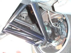 Rear control arms and brakes
 -
Jon's 2 year roll cage saga...
74_5.0L_Z replied to JMortensen's topic in Brakes, Wheels, Suspension and Chassis
I made my cage in sections. The main hoop, the bars from the top and sides of the main hoop, and the rear strut bar were a complete subassembly. To make the main hoop subassembly, I tacked everything together inside the car and then removed it for final welding on the bench. A benefit to this was that I could paint the cage and interior before installing it. This picture shows the rollbar after painting but before final welding. The entire assmbly could be removed by tipping it forward and wrapping it out. -
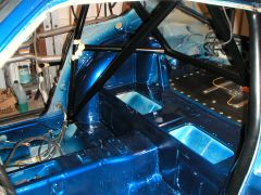 roll bar before final welding
 -
Where do I get 3/16 male to male 90* elbows?
74_5.0L_Z replied to auxilary's topic in Brakes, Wheels, Suspension and Chassis
something like this? http://www.secureperformanceorder.com/afcostore/getproduct.cfm?CategoryID=3&ClassID=36&SubclassID=150&ProductID=1817 edit:Nevermind, I see that you are still running metric stuff. One thing you should keep in mind is that Nissan ran the hard tube from the caliper to the hard point on the strut for a reason: The ends of flexhose are supposed to be mounted in planes that are parallel to each other. Otherwise the flexhose tries to rotate as the wheel goes up and down relative to the frame. The twisting can cause the barake line to loosen. As added insurance, the ends of the flexhose are mounted in clips to prevent rotation. Edit: double checked the military spec that details the installation of flex hoses (ML0102-306) -
With springs, the formula that relates deflection to force is as follows: F=K*x where K is the spring constant (i.e 250 lb / in) x is the deflection in inches from free length The deflection x is measured from the static position (no force applied) As an example, A spring is installed at a corner of the car with a free length of 12 inches, a rate of 250lbs/inch and a loaded spring height of 9 inches. What would be the affect of increasing spring rate to 300 lb/in and decreasing free length? First, determine the change by increasing spring rate: Assume the force at the wheel will be unchanged->F=k1*x1=k2*x2 therefore x2=k1/k2*x1 that is x2 = 250/300*3 = 2.5" The deflection of the springs is now only 2.5" rather than 3". If you were to only change spring rate without changing free length, you would raise the car by ~.5"(neglecting the angle of the strut). Now, if you want to lower the car while using the stiffer springs. Subtract the amount you wanted to lower the car originally plus the additional lift acquired by going to stiffer springs. Using the same set-up, assume that you wanted to drop the car 1.5" from its original ride height. You would need 300lb/in springs with L=12"-(1.5" + .5)" =10" 10 " 300 lb/in springs would lower the car 1.5" as compared to the same car with 12" 250 lb/in springs. All else being equal.
-
Smaller OD Adjustable Coilovers
74_5.0L_Z replied to tonycharger72's topic in Brakes, Wheels, Suspension and Chassis
I'm not sure of the exact number, but I know the following: With the stock springs, I believe that you are limited to wheels with a 4" backspace(the stock wheels have 3.875" BS). With coil-overs, I run a 5" backspace (15x8" and 16x8") with a fraction of an inch to spare. With coil-overs and wheels with 5" of backspace, I am able to run 245/45/16 under the stock whell wells. My coilover springs fit inside the stock springs with room to spare. The coilovers are also less than half the weight of the stock springs. Most importantly, coil-overs are cool. -
Brian, I have the edelbrock heads, Cobra Intake and Crower 15511 cam with 1.72 roller rocker arms. I installed these pieces somewhat incrementally and here is what I experienced. Stock......................Anything over 5500 was a waste of time. Stock + 1.72 rocker arms, 73mm MAF and 24# injectors............. a little more power but same rpm Add heads, intake, cam.............. pulls hard all the way to the 6250 rev limiter. I feel that the motor could easily pull to 6500 without any problems. I will probably install a chip soon to test that theory. With the 5.0L, the first hurdle to twisting past 5500 is the stock heads, intake, and cam. The stock heads don't flow well enough, and the stock valve springs are too weak to handle 5800 rpms. You now have a great set of heads with good valve springs. Unfortunately, the E-303 cam has a fairly narrow power curve that signs off at about 6000 rpms. You might consider a different cam. Crower and Anderson Ford Motorsports make some good ones. What intake are you running? Aren't you running a carburetor ? With the AFR heads, the right hydraulic roller cam, and the right intake 6500 rpms should be safe. If you really want to rev (above 6500) then install a solid roller cam. Anything more than 6500 though you should use better connecting rods.
-
Here are the dimensions of the main hoop used in my car: This roll bar fits VERY tight to the pillar (trimming of the interior plastic around the quarter windows is required). I should also mention that the bottom of the hoop is cut a ten degree angle to lean the hoop backwards parallel to the pillar.
-
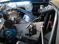
I do not use Alsil's crossmember, but I do have a 5.0L installed in my 260Z. Originally I installed the motor using the late model mustang rubber mounts and some steel plates attached to the frame. This worked pretty well, but if I were to rubber mount the engine again, I would build something similar to Alsil's crossmember. Here is a picture of the engine as it was installed on the rubber mounts: As you can see, I had to notch the bracket that holds the latch mechanism (ever so slightly). As stated earlier, the point of closest contact is the tube on top of the throttle body. I have about 1/4" clearance between the stock hood and the tube. Currently, my engine is mounted using a front plate/mid plate configuration. The engine is in the same location as before, but now it is mounted solid. A benefit of the front plate mid plate set-up is that it opens up tons of room under the engine.
-
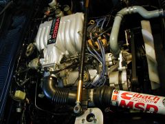
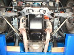 Bottom of engine (mounted with front plate/mid-plate)
 -
 Engine mounted with front plate to tube front end.
 -
 This image shows the engine comaprtment before the accident and tubular fron end