
74_5.0L_Z
-
Posts
1209 -
Joined
-
Last visited
-
Days Won
34
Content Type
Profiles
Forums
Blogs
Events
Gallery
Downloads
Store
Everything posted by 74_5.0L_Z
-
My combination is set-up for autocross, so I don't use drag slicks. My car weighs 2700 full of fuel with me in it, and has ~320 hp at the rear wheels. I am using the king Cobra clutch disk and pressure plate. I have had no troubles with clutch slippage since I installed it. I don't know how this clutch would perform under hard launches with drag slicks, but for me it works well.
-

Which brake set-up for autox/steet?
74_5.0L_Z replied to heavy85's topic in Brakes, Wheels, Suspension and Chassis
I am using option D (Outlaw stage II) on the front, and my own version of a stage II on the rear. For the rear, I am using the outlaw 2800 calipers with 1.625" pistons, 1985 maxima front rotors, and custom adapters. -
Well, after everyone's input, I have ordered the PC680MJT. It should be here in a few days. After it arrives, I will relocate my battery from the area behind the passenger side rear wheel well to the little shelf behind the passenger seat. This is about the easiest 30 lbs, I have left to remove from the car. In addition, relocating the battery will have the added benefits of a slightly lower CG and PMOI for the car.
-
Thanks for the reply. The Odyssey PC680 is a definite possibility. Is the car that you use it in a daily driver? Is it race only? How long have you had the Odyssey PC680 battery?
-
I was browsing the web for lightweight batteries, and I came across the brailleauto web-site. They have a couple of batteries that are extremely small and light (11.5 lbs for their race version and 15 lbs for their street version). http://www.brailleauto.com/ Has anyone had experience with these? Will it be compatable with my PowerMaster 100 amp 1 wire alternator? They seem like an extremely good way to shed 30+ pounds.
-
The comment about your grammar and spelling is not meant as a personal attack. You will be taken more seriously if you take the time to compose your thoughts. If you fill up the page with run-on sentences and misspelled words, then you come across as someone who doesn't think before he speaks. People like that tend to be ignored in life and on this site. If you have an idea or an opinion, take the time to express it clearly. We will do our best to return the favor.
-
Years and Models of all 302 EFI??
74_5.0L_Z replied to QuickSilverAWD's topic in Ford V8Z Tech Board
I have a 5.0L from a 1989 Mustang highway patrol car in my 1974 260Z. I used the factory 5.0L engine wiring harness and an A9P computer. Hooking up the wiring was one of the easiest parts of the whole project. It boils down to providing power and ground to a few wires, and to wiring up an EFI fuel pump. Before I started the project, I purchased the Ford EFI book by Charles Probst. This was a valuable tool, and I recommend that anyone wanting to install an EFI 5.0L buy this book. There is no complete kit for installing the 5.0L into the Z. Almost everyone who has done this manufactured their own. When I first put mine together, I used the late model rubber mounts. I have since switched to a front plate / mid-plate setup. I really like the latter. My car has been on the road and at the race track for over 5 years. I detailed much of the original installation in my early posts (circa 2000). You should really use the search function to look at my (and others') old posts. This will help you find answers to questions like: Which headers to use, driveshaft construction, adding a steering u-joint, what are your clutch options and others. Good luck, Dan McGrath -
I have Mike Gibson's Stage II (4 lug)brake set-up on the front of my car (since 2001) and a custom set-up on the rear using Outlaw 2800 series calipers and 1985 maxima front rotors. I have been very pleased with this brake set-up. Mike is a fellow HybridZ member and a very good guy to deal with. I personally recommend going with the Hawk HP-plus pads rather than the HPS pads. They make a little more dust, but have a lot more stopping power.
-
Cold brake performance
74_5.0L_Z replied to GAZRNR's topic in Brakes, Wheels, Suspension and Chassis
I tried the HB237-HPS pads and didn't like them very much for either street or autocross. I switched to the HB237-HP-plus and LOVE them. -
First, because the engine is from 1987, it uses a speed density ECM. What this means is that the computer decides how long to pulse the injectors based on Manifold pressure, Throttle position and RPMs. If you have vacuum leaks (especially if the vacuum leak is in the hose leading to the MAP sensor), then the computer will be confused and the engine will not run correctly. This problem should not prevent it from running altogether, but would cause idling problems. Have you pulled codes from the computer? That is usually a good place to start. If you are unfamiliar with Ford fuel injection, then I suggest that you get Charles Probst's book on the EEC-IV engine management system used by ford. It is a very informative book, and provides a lot of insight into the operation and troubleshooting of these fuel injection systems. The only item that I have had fail on my car is the TFI module in the factory distributor. These modules are known to eventually succumb to the heat under the hood. I looked into replacing it with a stock piece, but in the end I opted to upgrade to the MSD billet distributor that cames with new electronics installed. http://store.summitracing.com/default.asp?target=/egnsearch.asp&N=400122
-
I used the Chris Alston chassisworks front plate and a chassis engineering's steel mid-plate to mount my 5.0L and T5. They also have plates for the cleveland (P/N 6032). https://www.cachassisworks.com/images/6032at.jpg I believe you would use the same mid-plate as I do. P/N 3699 from chassis engineering. http://www.chassisengineering.com/viewcatalog.html
-
Cary, Coming from you, I consider that high praise indeed. Considering that I used pictures of the Tube80Z construction as inspiration. Dan
-
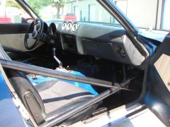
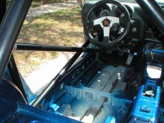
Some of the issues that I had to overcome in the construction of my chassis are the same as ones that you will encounter with add-on reinforcement. First, the z car is very narrow, and space within the passenger compartment is at a premium. In order to not crowd the driver more than absolutely necessary, it is mandatory that the main hoop is constructed to fit as tightly as possible to the B-pillar and roof. This foundation allows all attachments to the main hoop to be place as far away from the driver as possible. For a street car, the door bars cannot penetrate in to the door (much), and if they are being relied upon to provide fore and aft stiffness, they should be straight and triangulated. Second, the cowl area limits the height at which tubes can penetrate the firewall. In my design, I wanted to not modify the cowl and I also wanted to have the load path of the tubing go from the front strut tower, through the door bars and to the attach point of the main hoop. In order to achieve this, my door bar starts at the bottom of the main hoop and proceeds at a shallow angle to the highest point of the firewall allowed by the cowl. There, it penetrates the firewall and joins a cluster of tubes that proceed to the frame and strut tower. The shallow angle of the lower door bar forces the intersection point of the two door bars forward and down. Keeping the intersection point of the door bars low and forward has the benefit of making it fairly easy to get in and out of the car. In the following image you can see where the door bars penetrate the firewall and join the tringulated tubing thatsupports the front strut tower and frame. Here you can also see that the tubing has to be place as far ouboard as possible to clear the clutch master cylinder.
-
Yes, the bar going between the rear strut towers is welded to them. These are the only pictures I could find of the front inside of the car. Here is a picture of the interior after it was reassembled. The tubes of the door bars penetrate the floor, and are welded to the cluster in front of the firewall, and attached to the front of the rocker panel with a gusset.
-
-
-
This was my solution to the whole chassis reinforcement issue:
-
Rear suspension design
74_5.0L_Z replied to dj paul's topic in Brakes, Wheels, Suspension and Chassis
Thanks, Would you mind clarifying the last sentence? What kind of bad things? -
Rear suspension design
74_5.0L_Z replied to dj paul's topic in Brakes, Wheels, Suspension and Chassis
I've been thinking of this topic for several weeks. The people on this forum always seem to read my mind. I began thinking in terms of doing the rear suspension to increase the amount of backspace available in the rear wheel wells. I drew up some ideas, and decided to analyze the suspension I currently had before making modifications. What I came up with is that the front needs alot more help than the rear. The front suspension gains about 0.75 degrees of negative camber per inch of bump, gains positive camber in a deminishing non-linear fashion as the wheel rebounds past the point where the LCA is level, and has a really high KPI (~13.5 degrees) The rear suspension gains about 1.7 degrees of negative camber per inch of bump, and is linear over the entire stroke of the damper. I decided that I will modify the front suspension rather than the rear. I may do the rear later after I have improved the front. What I am trying to decide is how much KPI to design around. I can run a longer upper control arm by using a smaller KPI (5 to 8 degrees), and I feel that a longer UCA is better because the roll center will move around less. I am also trying to decide how tall to make the upright. I am currently leaning towards going with the tallest upright height that will allow the ball joint to fit inside the wheel. -
http://forums.hybridz.org/showthread.php?t=75442&highlight=Dynomax
-
Have you checked out the new XP class in SCCA. This looks like a perfect fit for our Hybridz cars in national level autoX.
-
5.0L rear sump for cross member clearance
74_5.0L_Z replied to s3079893's topic in Ford V8Z Tech Board
I just measured, and my driver's side cylinder head is 1.125 inch from the fire wall. My firewall is unmodified, but you will have to remove the ears from the stock transmission mounts on the body. -
5.0L rear sump for cross member clearance
74_5.0L_Z replied to s3079893's topic in Ford V8Z Tech Board
I have a 1989 5.0L in my 260Z, and I have been driving it for over five years. The 1989 uses the rear sump type pan. In order to squeeze the engine in to the stock chassis, I had to do a couple of things: First, I moved the oil plug for the front sump from the front corner to the bottom. This gave me ~1/2" additional clearance, and made it possible to remove the drain plug from the front sump. Second, I put a 3/16" plate between the front crossmember and the frame. This created some more clearance. Third, I slightly notched the driver's side of the hood latch to clear the curve of the EFI intake. Fourth (this is important), I installed the engine at a 2.5 degree angle. This required me to adjust the angle of the differential to match. I raised the rear of the differential by removing the washers above the mustache bar. Since the original installation, I have wrecked the car and replaced the front end with a tubular chassis, but the engine is still in the same location (though now mounted using a front plate/mid-plate set-up). Here are some pictures that show the relationship of the harmonic balancer / pan to the steering rack/crossmember. -
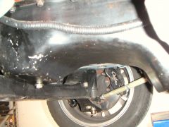 Pan to crossmember clearance