Tony D
-
Posts
9963 -
Joined
-
Last visited
-
Days Won
74
Content Type
Profiles
Forums
Blogs
Events
Gallery
Downloads
Store
Everything posted by Tony D
-

The start to something awesome #2
Tony D replied to yetterben's topic in S30 Series - 240z, 260z, 280z
This is total B.S. My cardomain page details modifications for the 81CAS so you can get well over max advance needed for any application. The Moby Sticky contains my comments on CAS interchangability, as likely will any search on CAS. Search the Tool Shed, likely it's been asked enough that several repeats have been flushed... The CAS is the CAS, the waveform is IDENTICAL. They are INTERCHANGABLE. The wires are THE SAME. -
Reference the original post, this was a R/S ratio for RPMS originally with a capacity of around 2.5L using an L28. That formula is more effectively accomplished with the L28/L20A destroke. (which also happens to have the same detonation resistance as the dwell and R/S is similar if not identical.) DAW, I AGREE, 'destroking' the LD block is ludicrous when L20A cranks are still plentiful. Some would say finding an L20A would be EASIER than finding the LD28 block to begin with!!! But improved R/S is available... There are pistons out there that will let you run L20B rods (check the length) in the conventional L28 Block. I know, I have a set...
-
Then you shouldn't say it can't be done. Your logic for not sleeving an LD Block for displacement INCREASE is the EXACT same logic I was arguing above for using a STANDARD L-Block with an L20A crank on a displacement DECREASE for 'rod/stroke maximization'.... So now I can play a particularly pernicious devil's advocate and say the logic works for BOTH arguments: if you disalow sleeves for displacement increase, then using an LD Block to convert to gas for a set 2.5 or 2.6 displacement has no advantages over simply using a standard L28 Block as you get the same R/S ratio with the L20A crank! This took a long time coming, but I'm glad you guys finally saw my point: For R/S Ratio, the cheapest way is to use the L28 / L20A combination---you get the R/S Ratio advantages and absolutely no conversion headaches: drop in and spin! NOW, if you are willing to commit $$$$$$$ to a project, then a WET LINERED LD28 for CAPACITY INCREASE is the route to go. The argument for a 'destroked' LD28 was economically foolish, you get the same results much cheaper using standard parts with the L28/L20A combination. The logical way to go with the LD is displacement INCREASE not DECREASE!
-
That elbow on the hose is a good idea, it lets people position the hose WHEREVER and negates the need to use an O-Ringed positionable elbow in the valve cover itself. While the cost of a hose-elbow is higher than a straight fitting, I'm sure the Earl's fitting is cheaper (and doesn't have a weld in it) that the other option. Well thought out solution. I really got to get the Milacron hooked up at the house. Bridgeport too... One day I will have time, at least that's what I keep telling myself!
-
No, what I'm suggesting is removing the plate and screw totally and letting the plates close completely. Then using a separate valve to control idle air from a separate source(the air cleaner, or something...) The screw on the linkage in combination with the rear bypass screw to synchronise off-idle synch. The throttles should be totally closed at idle, cracking them defeats the purpose of running EFI anyway. You will also find that if you have idle air bypass not related to the throttle bodies (like going into the balance log) you won't have the gunk buildup on the throttle plates nearly as much as if you crack them to make it idle. The stock TB idles with a bypass screw and plate totally closed. This should be no different. Having a single screw to adjust for idle speed (and only one bypass route) will make it easier to add the IAC Derek loves... Me? I got a 1/4 hose and needle valve, and I can get it up to 2200 rpms through that small line. This doesn't need to be a big line like stock, but it can be if you want it to be.
-
The start to something awesome #2
Tony D replied to yetterben's topic in S30 Series - 240z, 260z, 280z
Someone else said that in the beginning as well... Timing needs to move according to what is going on within the engine. -
late E88 head on N43 block checklist?
Tony D replied to 1978_280z's topic in S30 Series - 240z, 260z, 280z
Did you even read the cam information on the link, or just read what you wanted to read? It's a 74 260Z cam. All cam specs were listed in the Nissan Motorsports Catalog, just because it's listed doesn't mean it's some sort of high performance cam----it's a standard 260Z cam. The cam for an L20A Dual-SU Engine was even hotter yet, and not available in the USA so you would have to order it through Nissan Motorsports. Doesn't mean it's anything but a stock part. The "Nismo Oil Pump Springs" are stock parts from an LD28... For god's sake man, the information CAME from ZCar.com. What do you expect? Those guys think straight lock pulls and Broadway Mirrors are Nismo Parts. Hint: If it's not a 9/6-XXXXX series part number, it came from something STOCK in the Nissan Linup SOMWHERE in the world and you can order it (or buy it) in a car direct from the factory. You want a PERFORMANCE CAM from Nissan Motorsports Competition Parts Department, and not just a stock cam from a Japan Market Car, concentrate your search on the 9/6-XXXXX part numbers---THOSE are performance cams, all the rest are stock stuff that came in run of the mill production cars somewhere in the world. I mean for gawd's sake, the "-N36" on the second part of the cam part number means it's from a Stock 260Z. Or should I start marketing all my 260Z Manifolds with "N36" on the casting as 'Nismo' parts? It has to be true, I read it on the internets. (And ZCar.Com is listed as the source, so it HAS to be doubly true!) -
That plate and screw was only for setting fast idle (checking it actually)... The original SU's used two small screws on the carbs to crack the throttles (bad for kpa). The 73/74 SU's used a unified throttle bypass that took gas from the front carb through a jet system, and then put it to the balance tube---with the throttle plates FULLY SHUT. I found the larger single screw easier to set as well as quieter then smaller individual units. Sounds like if you closed the back screw all the way, and made the throttles evenly shut, you could balance using the screw up front on the linkage, as well as slightly cracking the back 'idle bypass' to equalize flow through the barrels (like a similar passage on Dellorto Carbs to balance flow barrel-to-barrel if the shaft gets twisted.) What is your idle AFR (full of questions, ain't I? )? I found tip in MAP excursions went quite rich due to the rapid MAP response of the stock linkage on SU Bodies converted to EFI. I ended up putting a throttle cable on with a wildly eccentric cam to tone down the tip-in response and mellow the MAP changes. Similar response like yours, half to 3/4 pedal travel to get about 30% throttle angle on the bodies. That seemed to really make low-speed and cruise modulation very easy. Even on a car with a stock cam and 40kpa at idle (best I could do was a 39/40 flicker at stock idle speed compared to 35 with the single body on a plenum.) the non-linear throttle worked wonders for making it easier to tune. Then again, running it really rich at idle seemed to help as well...
-
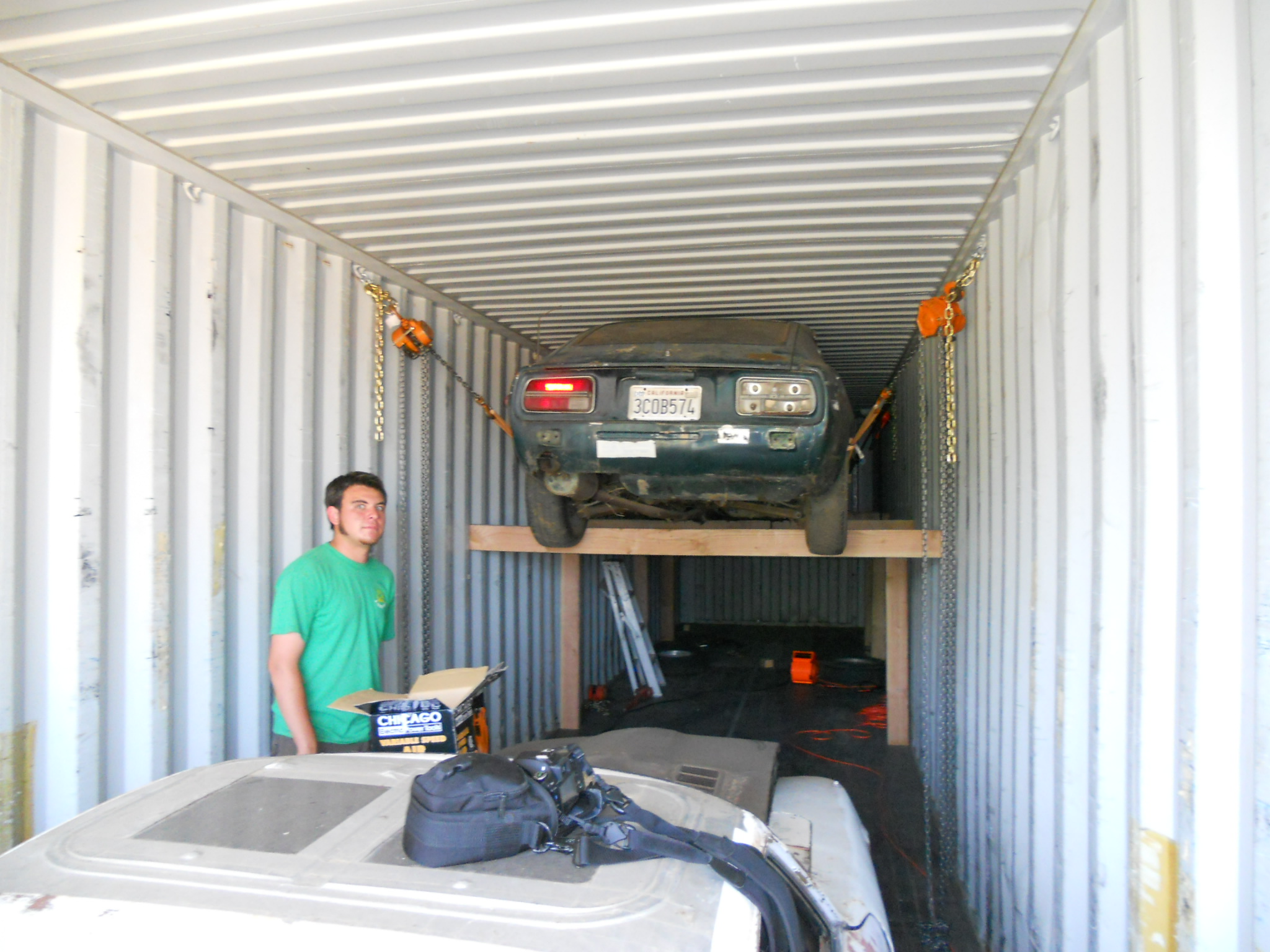
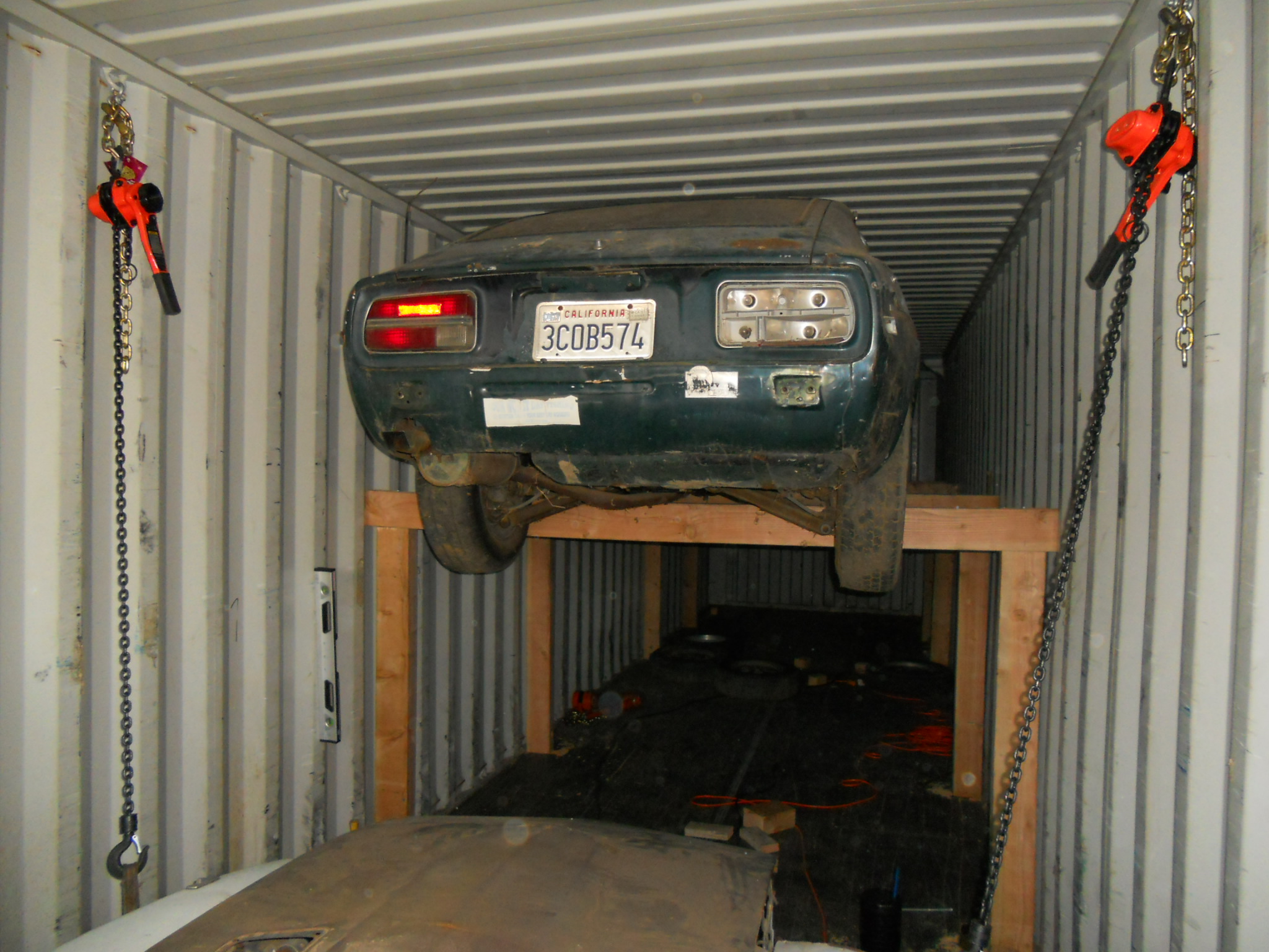
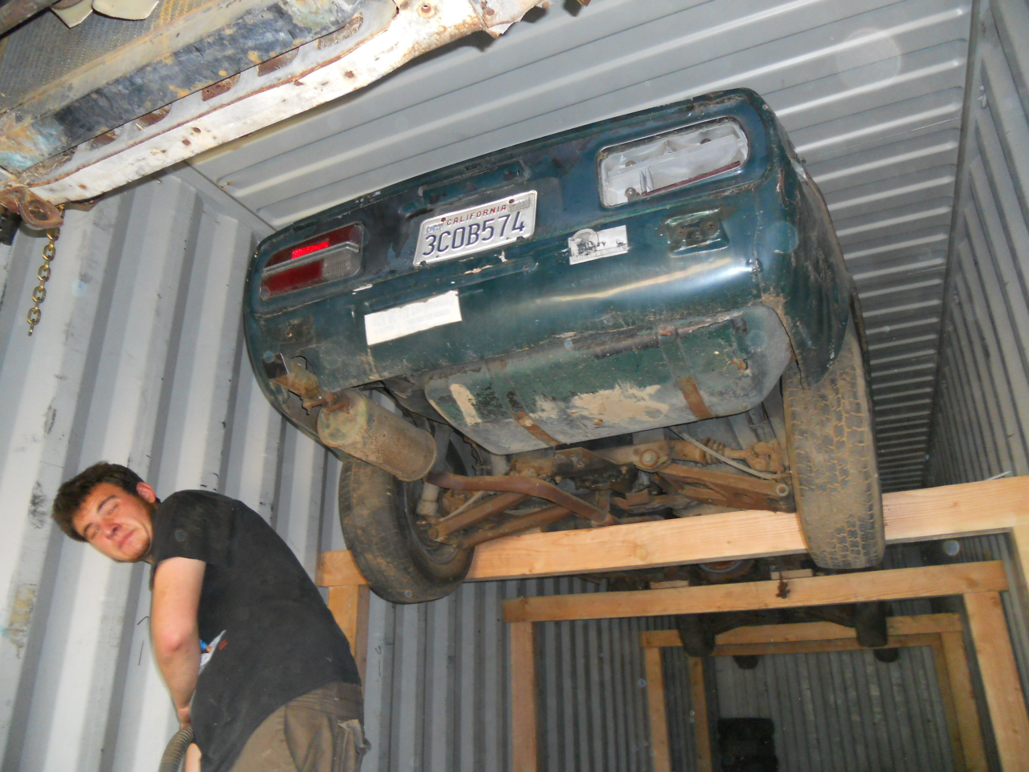
Dang, just hung a 71 up in the rafters last week that was painted the same color! I got to agree with Yetterben on this one, I would not sell the above chassis for $1500, as I know I can broker it in Europe for 2X that EASILY. If you need some sort of statement, like from 'A local Sports Car Club Officer or Director' PM me, part of the oldest Z-Car Club in the world just a wee bit north of you and can send something on club letterhead if need be in regards to what a NON-RUNNING stripped chassis sells for on the export market (giving shipping dates and destination!) As for the one above.... I don't think I will be moving it anywhere for a while, would have to move three cars to get to it now!

-
The weight of the Pig GTR coupled with it's AWD Traction would have avoided the spinning of the wheels on some of them. Had to get a running jerk going, and then the post FLIES up a bit... Of course pulling the cars with the same car (9 moved already) was good, till the 2+2 locked up a drum...I smelled clutch a bit and the wheels were spinning in earnest till we decided to jerk it backwards a couple of feet to unjam the shoe. Then we decided it would be best to simply put a tire between the two cars and use the 'push car' method to push it into the final storage spot instead of manually pushing it there... You should see how much my kid enjoys running around on the old bedsprings behind the 260 when we go weed the back yard with it! Who needs to go to the beach when you got a 260, some rope, a couple of matresses that have the soft stuff burned off, and a couple of acres to clear of sage and other low-growth weeds! Beats renting a Kubota with a Disc on it to till them under again...
-
Check out Travelex as well, that exchange rate you are giving is a heluva lot better than it was when I was in Sydney last month! Cheers, thanks much.
-
late E88 head on N43 block checklist?
Tony D replied to 1978_280z's topic in S30 Series - 240z, 260z, 280z
seals are the same, but lots of work for the E88 conversion, though depending on what the E88 came from may have identical compression ratio. "C" cam is just another variant of a stock cam, not a NISMO unit. Why not just get another N47 head for it? They are easy enough to come by, and cheap when they are found. If you were going carbs, I'd say go for the E88 (which if it is off early car may have smaller CC's in the head, and higher compression...) But for EFI, I'd stick with an EFI head instead of trying a 'conversion'... -
It wont go unless you have a 280Z with a full-sized spare---the space saver will have you making support brackets for the top of the tank as the 240 tank is significantly smaller in the spare tire area than the later (6-76 on) 280Z tanks. Midub has no location listed, but you two other guys in the IE and Los Angeles are in luck, I happen to have some late model 280Z tanks I might let go, PM me if you need one. They are baffled more than a 240 tank, and the pickup is a decent size (7/16" Hose 11 mm) compared to the 240 tank (5/16"-8mm). Return is same situation, 240 tank has a dinky 3/16" line (4mm), while the 280 tank has a 1/4" (6mm) line.
-
Then you would probably have an issue with my using the S30 to pull fenceposts last weekend, huh? No joke, they got chain hooks on em, couple wraps and pop it in reverse, and they pull right out. Cheaper than renting a Kubota and using a bucket to rip them up. Yes, if the chain isn't long enough, the metal posts will scratch the hood. When you see the scratches, now you know what caused them JohnC, so don't ask!
-
Concur, that movement may help idle resolution and I'd idle it at 900 at least. That really helps be equate some other stuff I messed with, I considered using an e-motive with their PAFZZBlend style mix program to make throttle progression off idle smoother. Are the throttle plates totally closed at idle, with the only air coming from the bypass screws? I found making they were totally closed, and using a single bypass screw to the manifold balance tube helped lower my idle KPA for better Speed-Density response. Actually putting a ZX Idle Bypass Screw (the one that mounts on the side of the plenum of the 82-83 ZX's) with a hose to the air cleaner (or at first a little K&N Cone slipped on the one fitting!) really helped lower the kpa to a more managable level so tip in enrichment wasn't triggered. A stock L will idle at 35kpa at stock curb idle (what, 700rpm or below). So anything in the 40's would be totally satisfactory. I found anything over 50 kpa on the MS to be a bit tricky to manage for the above reasons. A non-linear throttle linkage helps keep the manifold from experiencing spikes to 100kpa on little openings. Good luck, thanks for the numbers, that's better than I thought I'd get. Really helpful, appreciate it!
-
Do my eyes decieve me or is this a Datsun based replica?
Tony D replied to rturbo 930's topic in Non Tech Board
Those were my thoughts exactly. Little-"Richard"... -
What's the problem? He bought the car he wanted. I'd select it over an Altima as well. I would have sure as hell picked an R32 over an 1989 Maxima if I'd had the choice at the time. What's your problem? So he beats on the car. So what? It's his, he drives it in New York city what do you expect for a winter car? AWD makes for good driving in the winter conditions, just like a WRX---when was the last time a city car DIDN'T get dings and dents in NYC??? It's a freakin' car, get over it. Deification of the GT-R is something I never understood. "After all, it's just a Datsun" The GT-R guys hate that line, but it's because of the root of truth inherent in the statement. <EDIT> If this isn't the Hoboken-centric Hudson Valley Wal Mart, and it's the one upstate in the Catskills, substitute 'Upstate NY' and drop all that stuff about the city as driving upstate is just as brutal all winter...
-
Where in Longview is there long stretches suitable for this that is private property? PDX?
-
Stock Hose is a -10, actually, don't undersize it! Matter of fact, lower and upper are initially 15mm (-10) and the high vacuum unit that goes under the manifold transitions to 12mm (-8) at the manifold PCV Valve proper. I would say you should probably keep the low vacuum (air filter restriction at WOT) hose at -10 size (15mm, 5/8") That $50, is that shipped, or the part itself. What of the -10 part? Thanks for the feedback so far. Looks like I was over by about $100. Then again, I was thinking of stainless steel fab, and not aluminum...
-
If the 60mm is connected to the same linkage as the 50mm was (the vast majority of setups out there, most people seem reluctant to expend the effort to go cable or alter linkage geometry) the tip in can be attributed to delta-change for equivalent angluarity change on the throttle shaft. It's not attributable to linkage. Which was the point all along: induce non-linear actuation (through alternate geometry or cable and eccentric cam). For the same 20 degrees of throttle shaft rotation, the 60mm flows more, and makes more relative change in airflow capacity than the 50mm, that is why it 'tips in' harder. I would classify the stock linkage as linear, and the cable as equally linear, but without any mechanical slop. BOTH systems need alterations to induce a NON-Linear response in the first 35-50% of the throttle pedal movement. Someone can verify this: Stock pedal and linkage moves (Example) 25%, Throttle Body Shaft moves X% (say 25---or equate to degrees, say 22.5 degrees rotation). At 50% you have 50% throttle (or 45 degrees Throttle Shaft Rotation). What you want is to alter this so that for that same pedal travel of 25%, you get <25% Throttle Body Shaft Movement. In EITHER case, 100% travel of the pedal will always equal (or should) 90 degrees of rotary motion on the Throttle Shaft. It's like a valve characterization pair. Normally it's 1:1, but if you could do it electronically it would be more like Pedal Movement:Throttle Body Rotation 0%:0%, 10%:1%, 20%:5%, 30%:10%, 40%:15%, 50%:20%, 60%:25%, 75%:35%, 80%:50%, 85%:60%, 90%:75%, 95%:85%, 100%:100% From a graph of those pairings you can see that the first 75% of throttle pedal travel will take you to highway speeds and cruise easily enough. Once on the freeway the pedal becomes 'on-off'... Once you characterize the response you want graphically, you can calculate what you want, and equate it to linkage angles, or even a custom CNC profile for the throttle cam. The important thing is you have to figure out where 'normal driving' occurs and deaden the pedal to that point, and understand that 85% of the cars driving will be done there. After that, you are definately wanting full power and modulation becomes less of an issue. If there was datalogging available in the OP's car, I'd say watch the TPS inputs in the corners where the issue occurs, and deaden the pedal past that point. If he's having modulation issuesat a TPS of below 50% (45 degrees rotation, and I'm betting it is) then deaden it to that point plus 10%, and make the throttle 'on-off' progressive past that point. In straightline or drag racing it won't make much difference. But where sensitive throttle inputs occur, this will make the car feel more 'driveable' (easier modulation)... We have to do this to linear caged valves on unloading (blowoff) valves --- instead of changing their response characteristic to non-linear we electronically alter the control signal so the linear cage ACTS like a non-linear cage. The operator never knows the difference, for all intents and purposes it ACTS like a totally different valve. I do this every day at work, I kinda got a handle on valve characteristics. Fixing this is a simple matter of linkage geometry once you know where you want your response characteristic to be. Electronically or mechanically, the approach is the same. <EDIT> I'll add that the throttle pedal in a late 90's Suburban is much like this, you rest your foot on the pedal and you will stay at 55-65 mph. There is resistance via spring to hold you at a cam breakpoint. This breakpoint is at approximately 75% of throttle pedal travel. You think the thing is a lumbering wallowing beast because it just takes a LOT of pedal movement to get it going. But it works to save gas and makes driving the truck easier. Whoming the pedal past that point makes power come on QUICKLY. Doing a WOT (which you have to press VERY hard to achieve) results in squalling burning tires. GM toned it down so that the 90% of peopel that drive it don't come back with complaints about 'touchy throttles'. You can do the same thing, it's all geometry.
-
You line up the dots and install it. If you engaged it properly and didn't twist it on installation inadvertently and the drive gear has not spun on the shaft previously then it will line up. If it's off, then you take it back down, move the gear slightly and re-engage it however many teeth off you need to be to get it looking like the photo in the installation manual. If the gear has slipped previously....you put it where you need to, marks are irrelevant. And from that point pray the thing doesn't slip and throw out your timing (move the rotor position) while you're driving. Seen it happen several times on the dyno. I pin mine now, from new, with a 3mm hardened dowel before installation. It won't slip then!
-
"But the threads are very fine I'm sure some place for $200 they can machine you a custom adapter so you don't have to run a simple tap down the hole to get it to fit." Apparently they exist in Oz...Queensland to be exact. And the cost, plus EMS shipping from down under is? Inquiring minds want to know.
-
Paint it myself or $600 maaco paint job?
Tony D replied to 72_NorCal_240z's topic in Body Kits & Paint
Half a day a week? Doubt it... ( Holy Necroposter, Batman! ) -
Congratulations, that must be as satisfying as finding a sheep in chest-high grass next to the roadway... What is your idle Kpa reading, incidentally? And is that cammed. (Comparison to some stuff I've done in the past...)
-
You're Screwed. If you wanted A/N fittings in it, the time to do machining and heating was before it was powdercoated. You can try to heat it, or just horse it out of there. Or break it off with a hammer then machine it out on a mill or drill press. That may be possible. But the threads are very fine I'm sure some place for $200 they can machine you a custom adapter so you don't have to run a simple tap down the hole to get it to fit. If you want it without effort, you don't want it bad enough...