Dat73z
-
Posts
852 -
Joined
-
Last visited
-
Days Won
8
Content Type
Profiles
Forums
Blogs
Events
Gallery
Downloads
Store
Everything posted by Dat73z
-
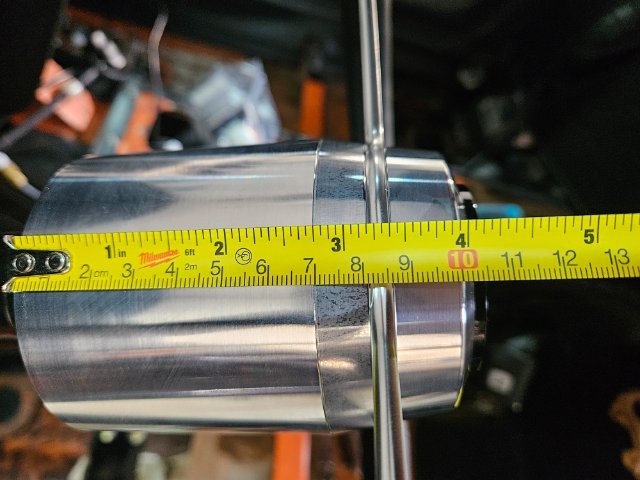
It's actually AL tubing but I was using stainless instrument benders to bend them. That's a good point on the sweating, I actually had the same question and emailed Vintage Air tech last year here was their response: "The only line that should sweat would the #10 suction hose/line, make sure this branch is insulated on the hardlines or metal sections of the hoses that are inside the cabin." So it doesn't sound like any of them should sweat but I'm not AC expert. I'm sure some insulation on the appropriate branches would increase efficiency so I may consider it at some point but I'm just trying to get the car back on the road first.
-
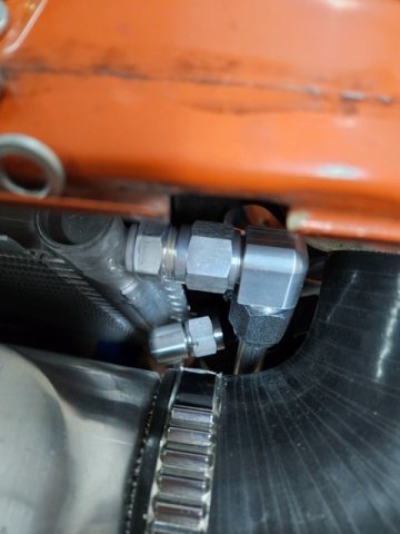
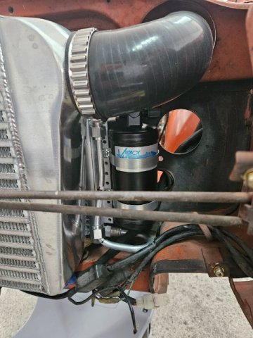
Life was getting crazy and I had to take a break from the project for a while but I'm hoping to get back into things this weekend. Where I left off I was mostly wrapped up the AC hardlines for the tucked AC setup. I have a workable solution which clears the intercooler/hood hinges + springs now but have some alternate routing in my mind for a cleaner aesthetic. The most limiting factor was minimum bend radii using my stainless hardline tools and basically I had to rely on changing directions to make the angles work in such a compact area. I think most people just say screw it and run softlines all the way around the engine bay 😂 I left fabricating the condenser soft mount brackets for last as I wasn't sure how much things would need to move to accommodate the hardline tool limitations so I'll focus on that next along with hardlining the oil cooler. Once that's all sorted, the intercooler can go back on and the turbo cooler packaging updates for this service will be complete.

-
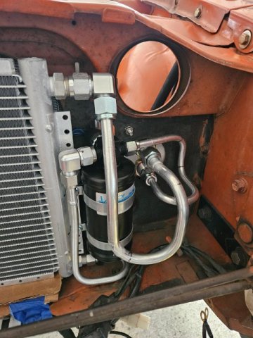
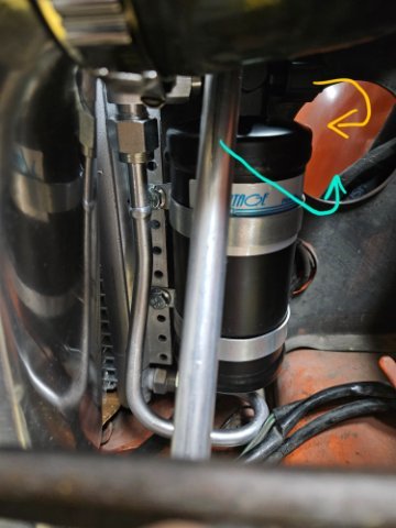
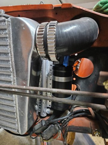
Today ran away but I had an hour in the garage so I continued on the AC condensor situation. I sectioned and welded the no6 hardline from the condensor to the dryer. Due to the SS hardline tool minimum bend radii I need to rethink the routing a bit. Everything just barely clears the intercooler though which is the most important thing.
-
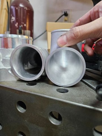
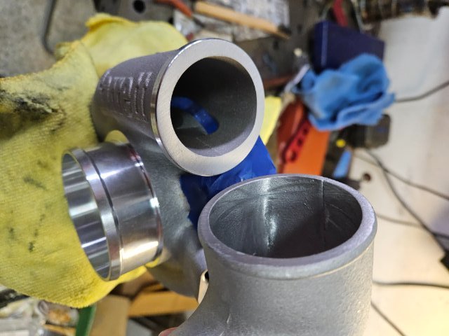
Just got back from a nice end of year vacation to some boxes of parts so I started back in on the build. I mostly finished cleaning up the turbo castings in preparation for welding, which to be honest I didn't realize just how bad the castings were internally until I started really blending things out. I also started bending up the AC hardlines in preparation for sectioning and welding. AL lines are super easy to work with compared to SS but all of my tools are set up for SS hardline fab so some of the bend radii are slightly larger than what I could probably achieve on the AL. -10 AN fittings also came in for fuel hardline, so tomorrow I'm going to drop the tank and start back in on the tunnel.
-
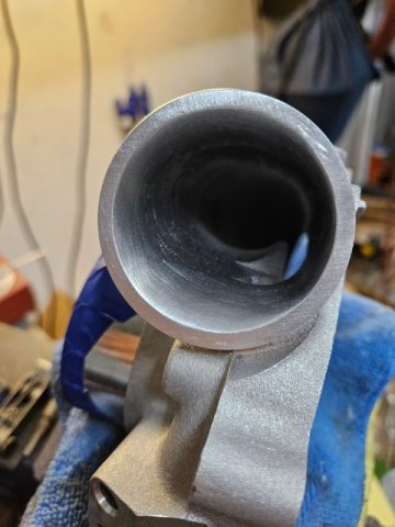
Some quick updates, still waiting for parts so tonight I matched the turbo compressor discharge to a cast 90 elbow in preparation for welding. I also picked up some 4943 tig wire which I'm excited to try out on a few components I need to weld. Next week, I have a few days off so I'm hoping to knock out the rest of the fuel hardlines and get caught up on some other fabrication work.
-
A musician's therapist (The $300 Z)
Dat73z replied to Zetsaz's topic in S30 Series - 240z, 260z, 280z
Personally I have almost solely used Hondabond moving onto 2 decades now and I always use an OEM oil pan gasket, rear main, and side seals. For the pan make sure it is absolutely straight all the way around verified on a flat surface, otherwise any slight bend or wave and you'll start leaking again. This includes the bolt holes which can get dimpled and ovalled. I got frustrated enough with the OE pan that I eventually went AL pan with a machined flat surface. -
A musician's therapist (The $300 Z)
Dat73z replied to Zetsaz's topic in S30 Series - 240z, 260z, 280z
Take a really close look at those side seals as well. I did a rear main once on an L then got to do the job all over again along with the pan when I got the car back together realized the side seals were also leaking, masked by all the oil and years of grime on the rear of the block. -
Now that the year is finally winding down I'm actually able to spend more than 30min blocks at a time working on the car. Tonight I measured things up for the condenser hardlines and bent up some tig wire as templates. I also ran the AC softlines into the DS fresh air duct as the intercooler takes that up on the rad support. Basically it'll be a tucked AC setup. I could probably have most of the AC system invisible in the engine bay actually, if I was willing to exit the softlines into the fenderwell. I'm also contemplating fabricating a AC line bulkhead using the OE rad support holes like I did for the oil cooler. It'll add complexity and parts cost to the project but like the oil cool I think it'll be a cleaner solution. With the holidays I probably won't get any materials I order until the new year anyways so I guess I'll sleep on it and decide next week.
-
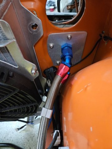
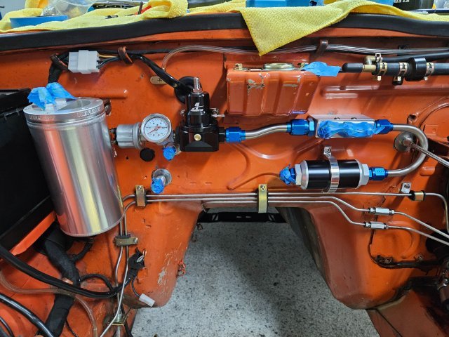
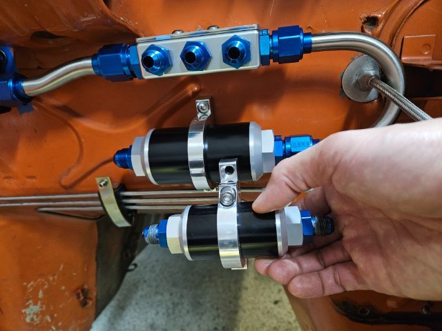
I wrapped up the fuel system mounting in the engine bay and realized I was missing a couple of AN fittings so while those are on order, I moved back to the cooler packaging. While the AC drier can really be mounted anywhere, including the cabin I wanted to keep everything tight in front of the radiator support. After some further mockup and measurement I realize I'll need to hardline most of the condenser packaging, as the packing including the trinary switch is just too tight for soft lines. What I found interesting about AC hardlines is there are no handheld tools that I could find to produce AC oring flares. Everyone I called who produced hardlines mentions they have some large proprietary hydraulic machine. So this limits me to purchasing pre-flared lines in varying lengths, such as those from Vintage Air, to bend myself and/or section and tig weld back together as necessary.
-
A musician's therapist (The $300 Z)
Dat73z replied to Zetsaz's topic in S30 Series - 240z, 260z, 280z
I'm also going to Vintage Air hardlines to clear all of the cooler packaging, and running everything else tucked on the DS reduce bulk. Another option are the EZ Clip style lines and hoses from Eaton, Vintage Air, etc. I'm running those in the cabin and they're much smaller in diameter with much tighter bend radius than traditional AC softline. They can also be disassembled for service or re-clocking unlike the crimped soft lines. -
Last night I mostly re-laid out everything on the firewall, close enough to finish fabricating the rest of the lines at least. Sort of tempted to start welding up the unused holes in the engine bay and shave things a bit, but I know that will turn into a major project so saving it for when I repaint the entire car someday. It'll also be interesting to see how the bulkhead heater fittings I put in for the vintage air will look with the OE hoses, but won't get that full view until the engine is back in.
-
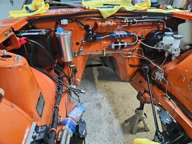
Last weekend my buddy came over and we pulled the motor as it made sense with all of the work going on. Everything only took about an hour and honestly I think we spent more time eating at a buffet and catching up afterwards 😂 Everything is easily accessible now so the plan is to finish up the hardline work on the chassis + setting up all of the new turbo and manifold(s) on the engine stand. This past couple of evenings I've been bouncing between projects, but for the turbo rebuild redoing the fuel system to -8AN feed and -10AN return SS hardlines. The physical dimensions of all the components are much larger, but through careful fabrication I'm able to mostly reuse the mounting locations from the prior setup limiting any new holes. Earlier on the fall I also had new -8AN and -10AN hardline clamps machined for the tunnel so later this week I'll start fabricating up the new lines into the previous mounting locations with the new clamps and around the new CD00A transmission which occupies a lot more tunnel space. SS hardlines, especially in large diameters are always challenging for me but I think the end result is worth it. This will also likely be the last fuel system I put into the car because I can't see a scenario where I'll need larger than -10AN and -8AN with 450 pump(s) on a L series.
-
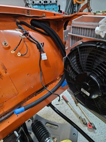
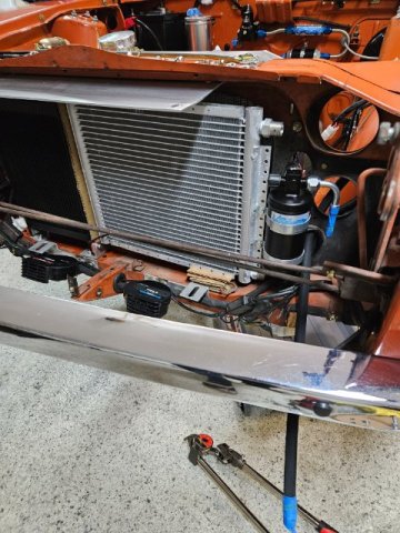
This winter I've been making good progress on various aspects the build, but most importantly getting back into the groove of one mini project per day. Tonight I diassembled the frontend of the car to revisit the cooler packaging. In the last iteration of the build I had intentionally left enough room to mount a half-size AC condenser, which are popular for other turbo cars such as evo's running large forward facing turbos. The packaging is extremely tight as I wanted to retain the hood springs while running a large oil cooler and condenser behind the fmic. I also left enough room for the option to run a 2" thicker core fmic in the future. I did have to mount some new PIAA horns as the OEM units would not fit. After some measuring, the plan this week is to SS hardline the oil cooler from the bulkhead fittings as although everything is functional I've never been quite happy with the SS braided hose. At the time I also didn't have the 10AN SS hardline bending tools and materials which I now have. Perhaps this will allow me to bring the oil cooler further to the pass side and give the condenser a bit more room as well.
-
Poly tank from Vintage Tank Solutions install discussion.
Dat73z replied to Derek's topic in Fuel Delivery
Look forward to your updates @Derek. I'm hoping to get to my VTS install early next year once I get some adapters machined for my in-tank surge tank. I agree all of the vents on the later 240z tanks makes a difference. I recall when I was deleting vents many years ago on my 1973, I ran into issues where I actually could not pump more than 1/2-2/3rds of a tank due to trapped air which was a major nuisance. So I went back to all OEM vents and the issue went away. -
Trust me when I say the heat from the turbo hot side effectively into your brake master cylinder and reservoirs even with a heat shield is not a good idea. Cruiser or not, it is dangerously close just from a heat perspective let alone movement of the driveline and even firewall/bmc from actually using the brakes making all of this worse. I'm not sure why you are opposed to simply cutting a flange you have already modified before and rewelding it to properly clear everything when you are willing to cut open the shock tower and elaborately plate it back in. Good luck
-
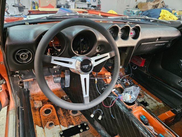
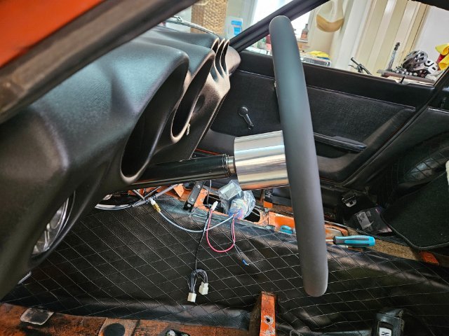
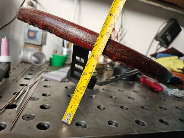
This winter I've been rebuilding the interior of my car. One item I could not find any information on at all were the mounting dimensions of the RS Mach Steering wheel. I believe in period this was a competition option, with the thicker wheel material and 380mm diameter often seen on the s30 and Hako Skylines. It seems the RS Mach wheel mounts more like the JDM s30 wheel compared to the deeper dish of the USDM wheel. Potentially I may machine a spacer to move the wheel further out but will see when I get everything back together. I know for the JDM s30 wheels it is popular to modify the turn signal stalk to account for the difference in wheel depth. I am also around 6' tall so also likely dimensionally different than the typical JDM person in period. Hopefully this helps someone. There is plenty of information out there for Checkman, Nardi, JDM s30 types, etc. types but nothing on this item. Edit: someone sent me some information and perhaps the Nissan comp part # was 48400-E4110. Apparently there were a few types of this wheel available, it would be good to know all of the variations but that'll be future research.
-
Poly tank from Vintage Tank Solutions install discussion.
Dat73z replied to Derek's topic in Fuel Delivery
@Derek I'm planning to run 2 vents. The fuel filler vent to the evap tank near the rear shock tower, which then goes to a one way valve and vents back into the rear fenderwell (I'll likely plumb in a charcoal canister for fumes). The second vent is on top of the tank on the fuel pump plate, also feeding back into the evap tank. Are you still having fuel tank backpressure issues? -
Not knocking your work, but what was the rationale behind cutting your shock tower in half which is a major structural component of your car versus reworking the Jpipe which can easily be modified or re-fabricated? It looks like even after severing the shock tower, your Jpipe still puts your turbine hot side into the brake master cylinder which has already been ground down? After looking through your build thread I see you modified the bolt-on jpipe from an old turbo kit. The chassis has already been cut but I would advise you remake or modify the jpipe to fit the turbo properly away from your brake system. You may be able to reuse your modified jpipe by simply changing the angle on either flange.
-
Thanks @calZ. Big fan of your work.
-
Reserving post 2 Also have a bunch more pictures and videos to upload. Not sure why but I keep getting upload errors so perhaps I'll focus on the written aspects first.
-
Reserving post
-
Misc.: Triple carb idle up solution Set a bunch of placeholders going to keep this post as a catch all. Open to any suggestions on what else I should add as I am working on this through the winter.
-
Wiring: Write this up later out of time today.
-
Refrigerant Charge and Service: Write this up later out of time today.
-
Line Branches: Write this up later out of time today.