-
Posts
208 -
Joined
-
Last visited
-
Days Won
2
Content Type
Profiles
Forums
Blogs
Events
Gallery
Downloads
Store
Everything posted by 280Z-LS3
-
280Z build w/ LS3 and 2015 Mustang spindles/8.8
280Z-LS3 replied to 280Z-LS3's topic in Gen III & IV Chevy V8Z Tech Board
Well, I have been racking my brain trying to get the Suzuka seat to fit. The widest point of shoulder bolster is 590mm and 500 mm from base of seat per Corbra diagram spec. Centering the seat on the steering wheel puts the shoulder bolster out past the door card. In fact, it looks like if the door were cut for clearance the shoulder bolster would extend past the window slot in the door. That means no window, no bueno! Measured the steering center to door face when closed is 300mm. Figured installing seat on center of wheel would yield a slam dunk quick placement with maybe a little touch on the door card given 590/2=295mm. Obviously there is more going on here... Most aftermarket fixed back seats are at least 590mm wide at bolsters. However, the height of the widest point off the base of seat does vary from short 500mm to 650mm. I don't see how a bolster positioned higher helps because it looks like the window will still get hit but guys have installed seats with these specs. Were they installed off center to the right of the steering wheel? I am short at 5'7" so need the seat more forward which places bolster near the door lock pull, farther back and my short legs start reaching for pedals. (This has me thinking about the length of steering wheel or moving pedals closer but that's a topic for another day). Maybe successful installs of similar sized seats depend on getting the seat moved way back putting bolster next to B-pillar? At this point success getting the Suzuka to fit seems slim to none. Damn shame because it fits me well. -
280Z build w/ LS3 and 2015 Mustang spindles/8.8
280Z-LS3 replied to 280Z-LS3's topic in Gen III & IV Chevy V8Z Tech Board
No pics. I have the "you weld" kit that comes tacked welded together. It was easier to just break the tacks on the mustache bar mount plate and move the corresponding amount to achieve desired pinion angle. Three things to look out for are resulting tightening clearance between frame rail and cradle (you are moving the cradle up), potential bind in the bushings on the two trans tunnel uprights (may have to break the tack welds and reposition the bushings cups on the plates) and check for pinion to forward transverse link clearance (pinion has moves down). Have not heard anyone with vibration issues with the Super 8.8 kit so this was not to fix any problem. I just am a hobbist who wanted things spec'd out at 2 degrees for the reasons I detailed above so take that for what it's worth. I would NOT slot the holes. -
280Z build w/ LS3 and 2015 Mustang spindles/8.8
280Z-LS3 replied to 280Z-LS3's topic in Gen III & IV Chevy V8Z Tech Board
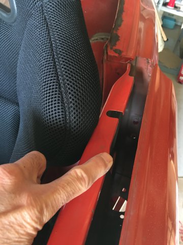
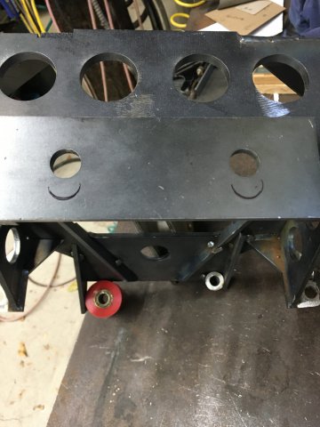
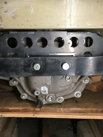
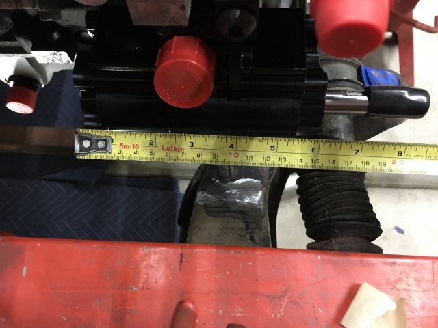
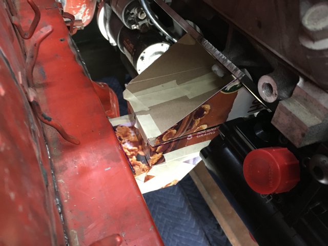
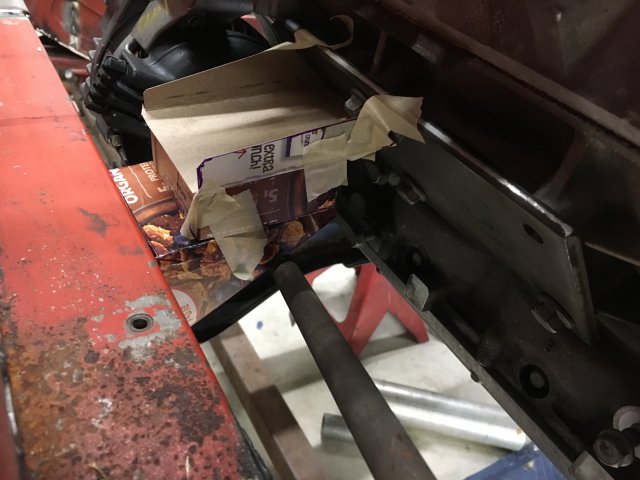
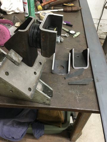
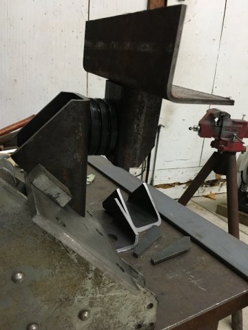
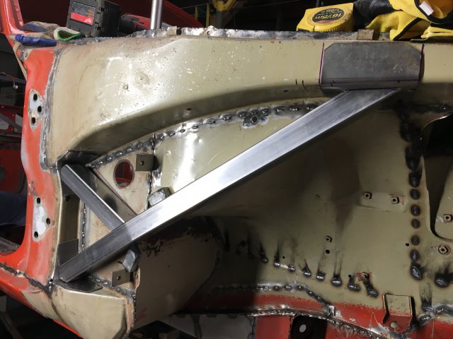
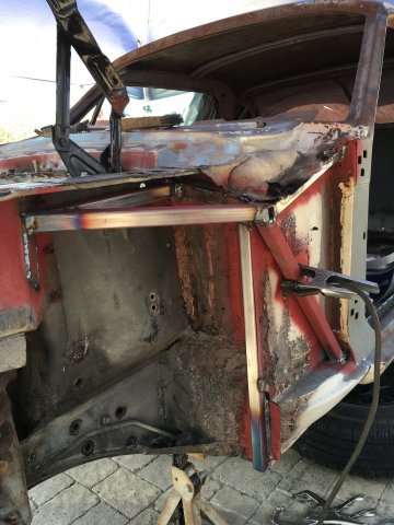
Update time! Since I am making my own engine and trans mounts I needed to think about drive line angles. After mocking up the engine/trans assembly decided 2 degrees engine/trans reward tilt gave me the best placement for bellhousing (above frame rails), intake manifold off firewall, harmonic balancer to steering rack clearance, positioning of transmission in tunnel, etc... To have the pinion angle an equal and opposite 2 degree up necessitated modifying the the 8.8 diff cradle as it positions the pinion with around 4 degrees up. I dropped the rear mustache bar plate about 3/8" which effectively raises the rear of the diff giving the 2 degrees up pinion angle. I basically removed the mustache bar mount bolts then jacked the diff up until I achieved desired angle then using the bolt holes in the mustache bar scribed where the new hole locations should be. I elected to to just move the hole plate rather than drilling new holes. Here it is installed. Cradle not fully welded yet. Now that the diff angle is set moved onto making some puck style engine mounts. Originally planned on coming off cross member frame like Hoke did in his kits. However, I ran into some clearance issues in keeping with the criteria of having the engine as far back and low as possible. The engine is to be set with the block to trans mounting face about 1.5" off the firewall. Having the engine this far back complicates having the engine mounts connected to the cross member. I have a three stage scavenge pump mounted on the lower passenger side in the stock a/c compressor location. I believe the scavenge pump occupies the same physical space of the a/c compressor because it is said to be compatible with the Corvette C6 engine mounts. Anyway, the amount of cantilever to get behind the scavenge pump seemed too large, somewhere around 4.5" from rear face of cross member, thereby creating a large torque arm that would flex/twist the cross member under WOT. Would have liked to move the engine slightly more forward (around 1/2") for more engine mount to steering shaft clearance but was prevented by the sump tank return oil fitting on the ARE dry sump pan (no pic, sorry). The fitting sits just behind the passenger side steering rack mount. I ended up with about 1/2" clearance between the oil fitting and steering rack. So on to plan B, have the engine mount come off frame rails. Using some cereal boxes I mocked up some mount templates. The driver's side mount does not have much overlap on the engine plate so I cut some gussets to weld to bottom to help distribute the load across the plate. I don't have a pic of those mocked up but you can see them on the bench. Will post when they are welded up. Here is a pic of the passenger side mocked up on bench with 9" 3/16" thick angle to reinforce the frame rails. The mounts themselves are made of cut 3"x.250" square tubing. Moved onto designing the trans mount which I am still in the process of figuring out. I need to get the Suzuka seat installed because that necessitates some trans tunnel surgery. where the trans mount will reside. My 1975 has the driver's side trans bulge for the catalytic converter competing for space. Here is the initial hole. And that's still may not be big enough! But before attacking the poor car again with the cut off wheel waiting on some OMP seat mounts. The really nice Cobra alum brackets purchased with seat have too long a foot print plus they sit really high. Cobra's description of these brackets say they offer the most adjustability but that just means they have the ability/material to drill some new holes and cut away material for lap belt clearance. Too much hassle for a guy that does not have a mill... Anyway the OMPs are 5cm or 2" shorter length and around 3cm lower in height. While waiting for the OMP brackets moved onto the front upper frame horn and T/C bucket to rocker supports. Used 1.5" 14 gauge square for the frame horn and 1.25" 14 gauge for the T/C bucket. The bend at the firewall on the frame horn tube is 8 degrees (pie cut sides and welded) and choose square over round tube for ease of stitch welding to body panels. T/C tube square only to match. That's all for now. -
Let's talk lighter weight clutches for LSX motors
280Z-LS3 replied to 280Z-LS3's topic in Gen III & IV Chevy V8Z Tech Board
Called Tilton today. Detailed my setup and intended use then discussed various options. Heard it enough now that it's starting to sink in that metallic plate clutches like 5.5" and 7.5" are binary. Jeff at Tilton tried to steer me to the ST-246 but that is around 40lbs with flywheel so didn't feel in hit the sweet spot. He went on to say they have a 8.5" kit in development with beta kits arriving around February 2021. It's basically a scaled down version of the ST-246 offered with organic and cerametallic disc options with a total weight of 25lbs. That sounds like could be a winner for my application using the cerametallic discs. -
Let's talk lighter weight clutches for LSX motors
280Z-LS3 replied to 280Z-LS3's topic in Gen III & IV Chevy V8Z Tech Board
Going to stay away from the metallic discs for sure. Tilton has a 7.5" clutch with cerametallic discs designed for some slip and I suppose other manufactures have similar friction material designed for applications requiring more heat tolerance. Correction, it's "stand type" clutch not "step type". -
Let's talk lighter weight clutches for LSX motors
280Z-LS3 replied to 280Z-LS3's topic in Gen III & IV Chevy V8Z Tech Board
Correction, its "stand" type clutch not "step" -
Let's talk lighter weight clutches for LSX motors
280Z-LS3 replied to 280Z-LS3's topic in Gen III & IV Chevy V8Z Tech Board
I have some experience with setting up a hydraulic throwout bearing, installed a Tilton 6000 series on a Centerforce clutch in my Mustang. Not hard, just detailed measurements need to be taken. -
Let's talk lighter weight clutches for LSX motors
280Z-LS3 replied to 280Z-LS3's topic in Gen III & IV Chevy V8Z Tech Board
In the situation of never driven a car with a race clutch so trying to access if the drawbacks of light clutch are enough of a concern to ditch the idea. EFI tuning and throwing belts are issues that have solutions. Want to go into this race clutch eyes wide open knowing what I am signing on for... This will not be a "grocery getter" by any means. It will see street driving to and from track/autocross events and spirited canyon runs. I think a button clutch is a "step type" and a "strap type" is the more conventional design I am most familiar with where the outer pressure plate housing is connected to the friction plate by straps. I have read on forums that the strap type is a form of torque management, would like to learn more about that... -
Working on limited knowledge a while back I purchased a Fidanza LS3 style recessed aluminum flywheel with the intention of running a LS7 pressure plate, disc and hydraulic throwout bearing. Not so certain I want to go this route anymore. The LS7 clutch/flywheel is 57lbs! Jeese, that thing could get a tow truck rolling... The LS7 flywheel is 26.5lbs and Fidanza is 13lbs so this nets a 13.5lbs reduction giving the Fidanza flywheel LS7 clutch a still porky 43.5lbs. Our S30 chassis cars with LS swaps are weighing in at between 2500-3000 lbs which really does not require a large mass flywheel/clutch package with large moment of inertia. Seeing guys with racing flywheel/clutch weights ranging from 15-35lbs used in LSX motors around the web. Now there are step type clutches and strap type. Can anyone help me better understand the differences between these and how "drivability" suffers as one moves toward small diameter racing clutches?
-
ANOTHER Datsun Z/LS3/T56 Swap Thread
280Z-LS3 replied to Ironhead's topic in S30 Series - 240z, 260z, 280z
Yeah, a nice piece of gravel free pavement and I'd be very tempted to throw it sides ways once an a while! I am not that accomplished as a driver but plan to expand my abilities in all ways... -
ANOTHER Datsun Z/LS3/T56 Swap Thread
280Z-LS3 replied to Ironhead's topic in S30 Series - 240z, 260z, 280z
Coming together nicely. How did you plumb the e-brake and rear brake calipers? More specifically, what's that lever on the rear bulkhead and is this designed for drifting? -
Congrats on a nice build and thanks for sharing.
-
Steel Datsun used for transverse link mounts?
280Z-LS3 replied to 280Z-LS3's topic in Fabrication / Welding
Yes, the transverse mount brackets are the two flat 3.5" wide brackets to attach the rear transverse mount to the frame. I have not tested the transverse mount metal with punch or any other method so not sure if it is made of the same hard steel as the brackets. -
I butchered up a pair of transverse link mounts at an attempt to design some cross bracing. Did not go well as expected so have a replacement set on the way. While employing my "hack skills" noticed that Datsun used some hard alloy. Anyone know what type of steel Datsun used and recommended/required welding and rod that should be used?
-
Electric power steering, use complete donor column?
280Z-LS3 replied to 280Z-LS3's topic in S30 Series - 240z, 260z, 280z
Haven't had the time to read through all the numerous posts on different forums. Grannyknot has a Vue/Equinox swap and he has posted his favorable experience with high performance driving setting. Maybe he can chime in with more detail on his experience with the Vue swap Agreed. Now for a few more dollars hoping to have a great system. -
280Z build w/ LS3 and 2015 Mustang spindles/8.8
280Z-LS3 replied to 280Z-LS3's topic in Gen III & IV Chevy V8Z Tech Board
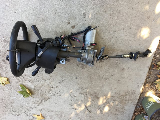
Building the roll cage is on the near horizon and that has me thinking of brackets off knee bar for steering column and maybe for Tilton pedals. I want electric power steering so started thinking of which EPS swap to use. After reading just a fraction of the info on web I decided to go with the 2002-2007 Saturn Vue option. Went down to the local u-pick yard and grabbed a 2007 Vue column for $65. Will order up a Bruno controller with variable assist knob off eBay. For now I am going to assume that I will retain the same OEM column length dimension to fit seat which is need to fit roll bar tubing. Still reading how others have adapted and installed the EPS unit so have not decided exactly which method and parts to use. -
Electric power steering, use complete donor column?
280Z-LS3 replied to 280Z-LS3's topic in S30 Series - 240z, 260z, 280z
Picked a horse in the EPS race. Went down to the local u-pick yard and grabbed a 2007 Saturn Vue column for $65. Will order up a Bruno controller. Now just need to decide whether to use the OEM upper column or start fresh with an aftermarket column. That all depends on the ease of adapting a quick disconnect hub for the steering wheel on both columns -
Electric power steering, use complete donor column?
280Z-LS3 replied to 280Z-LS3's topic in S30 Series - 240z, 260z, 280z
Thanks guys. Becoming more confident as I continuing to read the vast info available about the EPS swaps. As of now leaning toward the Vue/Equinox column with Bruno controller and either using stock upper column or aftermarket. Don't know if I'd like the "fail safe" mode with it's flat constant assist especially at high speed. A variable assist would be best. Wonder if there is a way to custom program variable assist based on VVS signal? Need to spend some time reading all the info on Vintage Mustang forums. Don't know if it's relevant that my front suspension is slightly different than stock Z (2015 Mustang spindle front suspension with 275 front tires) when it comes to how assist is dialed in for kits like Silvermine. It's a variable but is it large enough to make any real difference... -
Electric power steering, use complete donor column?
280Z-LS3 replied to 280Z-LS3's topic in S30 Series - 240z, 260z, 280z
Thanks Fusion, just sent Fritz an email. -
Electric power steering, use complete donor column?
280Z-LS3 replied to 280Z-LS3's topic in S30 Series - 240z, 260z, 280z
Looking at Silvermine's EPS kit. It uses an ATV electric motor from what I gather. That is not necessarily a bad thing, just not OEM proven reliability. Which off shelf solution do you suggest? My knowledge on EPS stuff is limited though eager learn. Looks like the popular OEM swap units, either those that operate in fail safe mode or need a 3rd party controller, are too short thus only good for hybrid adaptation into columns. -
Searching for those with experience using a compete donor EPS column. There are plenty of well documented conversions but they combine portions of both the stock column and donor column to make a hybrid column. I have Tilton pedals so the stock pedal box will be not used. Custom support brackets need to be made so why not just make them fit a compete donor column? Also, plan on a quick disconnect hub for removable steering wheel so there will not be much of the stock column left if were to go the hybrid column route. My first thought is looking for a EPS column with similar firewall to steering wheel distance as my 280Z. Would be nice if the donor columns proven for use in the hybrid conversions could work as stand alone by themselves. Thanks in advance for your thoughts
-
280Z build w/ LS3 and 2015 Mustang spindles/8.8
280Z-LS3 replied to 280Z-LS3's topic in Gen III & IV Chevy V8Z Tech Board
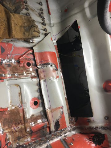
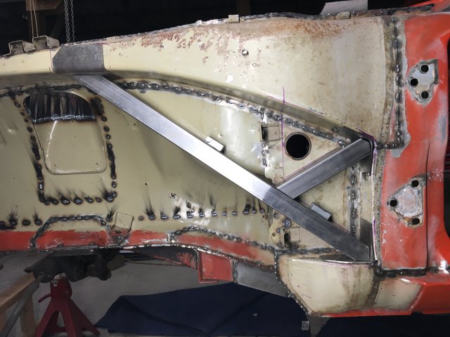
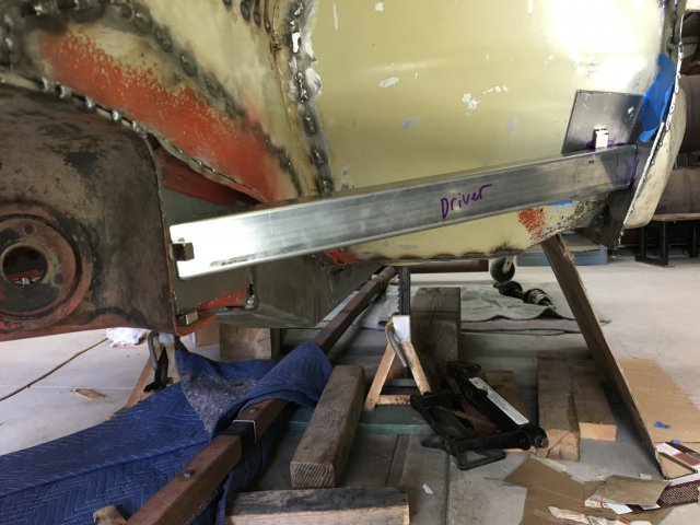
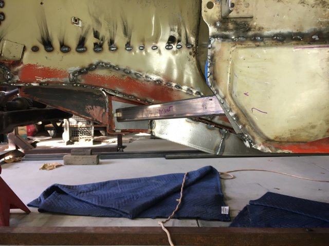
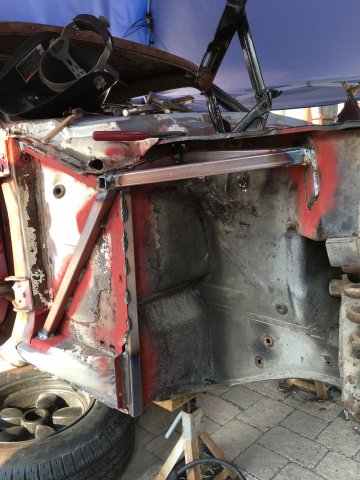
Cary, I like the torque box idea. Do you think 18 or 20 gauge is best for a torque boxes? Have you ever calculated what a Mustang type torque box could do for a S30 chassis? I have a 68 Mustang and will analyze the design tomorrow. From what I recall the bottom of the torque box is made of substantial plate, at least 11 gauge. That would certainly also help with a side impact transferring the force to the frame rail and wheel collapsing back up into the foot area from off center front impact just like the TC bucket to rocker support bar does. Trying to envision the benefit of boxing the upper frame horn, a-pillar and rocker. Is it just adding more support to the upper frame? Boxing this area is easy and does not interfere with any current plans. Here are some pics of front end bracing I did on my 68 Mustang. The torque boxes are clearly visible and honestly at the time thought they only consisted of the thick sheet metal connecting the rocker to the frame rail on the under side. Never gave them much thought other than the early Mustangs did not have any, the 1967 had only one side then Ford decided both sides should get them in 1968 . In the cabin the floor pan angles up toward the firewall and on the wheel well side the angled up floor pan is clearly boxed in. The top tube against the firewall which forms the base of the strut tower triangle runs across the top of firewall just under sheetmetal lip providing support for the strut tower to firewall "export brace".


