A to Z
-
Posts
1072 -
Joined
-
Last visited
-
Days Won
32
Content Type
Profiles
Forums
Blogs
Events
Gallery
Downloads
Store
Everything posted by A to Z
-

My Z car log....small jobs done and fun things
A to Z replied to A to Z's topic in S30 Series - 240z, 260z, 280z
parts are pouring in.
-
My Z car log....small jobs done and fun things
A to Z replied to A to Z's topic in S30 Series - 240z, 260z, 280z
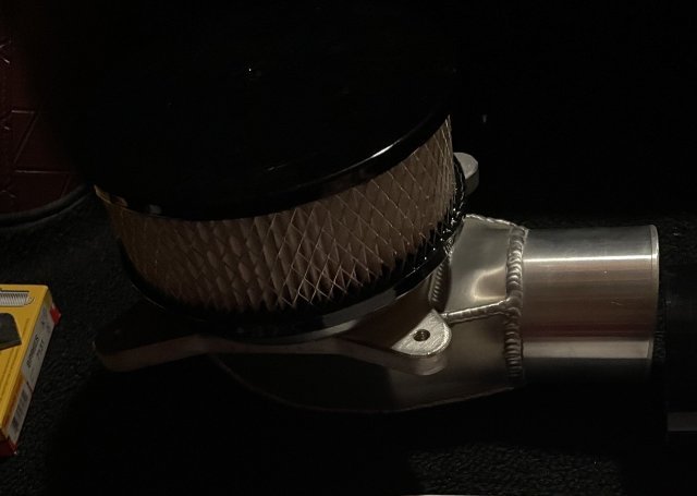
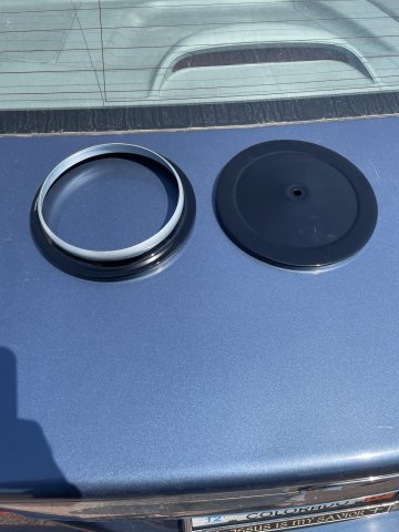
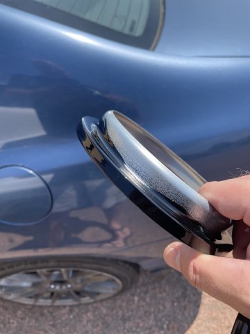
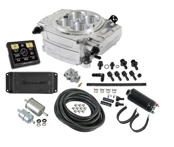
ordered a 9" air cleaner and I decided I didn't want it chromed AND the sniper to be polished, so I took it to a local guy and had it blasted and powder coated gloss black to set off the sniper a bit. the bottom ring is only powdered where it can be seen, as it won't fit on the mouth of the sniper if the powder is on there...too thick. I think it will look ready good and contrast the polished stuff.
-
My Z car log....small jobs done and fun things
A to Z replied to A to Z's topic in S30 Series - 240z, 260z, 280z
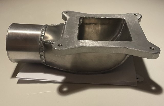
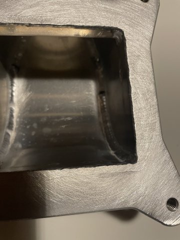
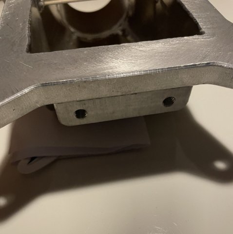
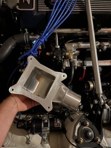
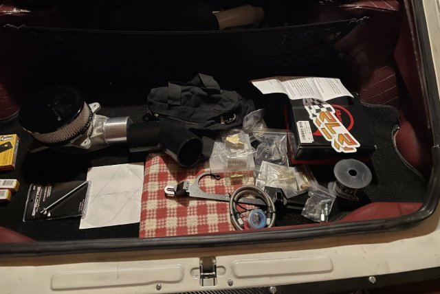
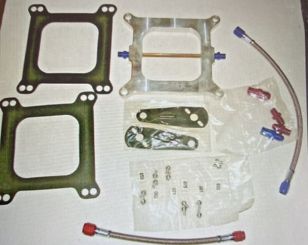
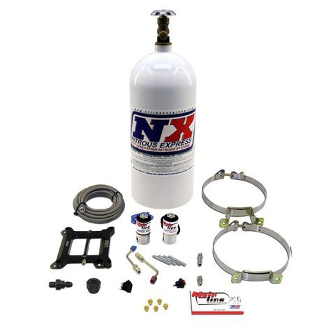
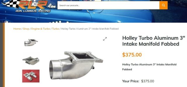
extra parts for the EFI conversion:
-
My Z car log....small jobs done and fun things
A to Z replied to A to Z's topic in S30 Series - 240z, 260z, 280z
I took a BIG leap today:
-
My Z car log....small jobs done and fun things
A to Z replied to A to Z's topic in S30 Series - 240z, 260z, 280z
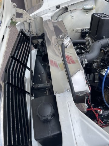
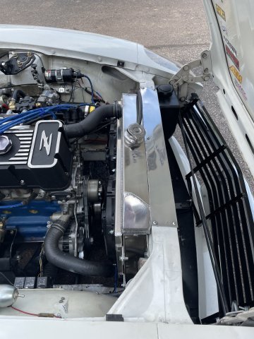
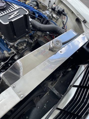
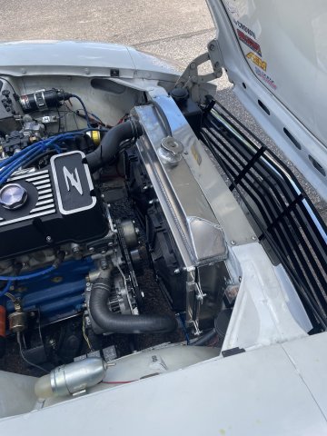
08-09-2025. Polished out the top of the aluminum radiator and the trim in front of it today:
-
My Z car log....small jobs done and fun things
A to Z replied to A to Z's topic in S30 Series - 240z, 260z, 280z
Thanks. the stock cam and the Diesel crank gave me that torque figure! -
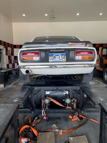
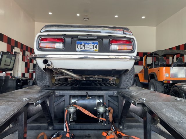
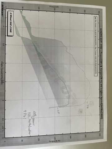
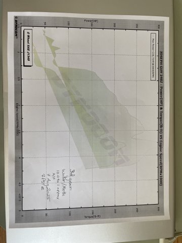
08-07-2025. DYNO morning. Found out a couple of things. 7 psi in 3rd gear WOT at 5500 RPM, 9 psi in 4th gear WOT 5500 RPM. She is RICH....rich to the point of fuel popping, 10.0 to 1, A/F rich, and didn't want to go past 5500 RPM (strange since on the road she will but nevermind). So, there is probably 40 horsepower left in her in the DYNO guys mind. We made 4 runs, and in 4th gear without using any Water/Methanol injection, it pulled 196.8 hp at the rear wheel, at 5500 RPM and at 18% drive train loss that is 232 hp at the crank@5500 RPM. Torque was 268.3 at the rear wheel, 316.59 at the crank@ 5500 RPM. Boost was 9 psi at 5500 when he had to let out because it was so rich. We did a run in 3rd gear WITH water/Methanol and it pulled 226.7 hp at 5500 RPM at the rear wheel, so 267 HP at the crank@5500 RPM and 260 torque, which is 306.8 TQ@5500 RPM, boost was 7 psi. So, as I thought when building it, the stroker and the stock cam made it into a torque monster. well over 300 ft lbs. torque, 232-267 horsepower.....but it is PIG RICH. So, power is limited by being rich. I have dyno charts, but the RPM range at the bottom is all wrong. we weren't able to get to 6000 RPM because of the rich condition. He said it was basically 10 to 1 A/F on the runs, which is WOT, so the main jet is just too big. I can step it down one. As expected, the carb is the limiting factor. At any rate, this is where this engine setup is at now. As predicted, it is a torque monster.
-
08-07-2025. DYNO morning. Found out a couple of things. 7 psi in 3rd gear WOT at 5500 RPM, 9 psi in 4th gear WOT 5500 RPM. She is RICH....rich to the point of fuel popping, 10.0 to 1, A/F rich, and didn't want to go past 5500 RPM (strange since on the road she will but nevermind). So, there is probably 40 horsepower left in her in the DYNO guys mind. We made 4 runs, and in 4th gear without using any Water/Methanol injection, it pulled 196.8 hp at the rear wheel, at 5500 RPM and at 18% drive train loss that is 232 hp at the crank@5500 RPM. Torque was 268.3 at the rear wheel, 316.59 at the crank@ 5500 RPM. Boost was 9 psi at 5500 when he had to let out because it was so rich. We did a run in 3rd gear WITH water/Methanol and it pulled 226.7 hp at 5500 RPM at the rear wheel, so 267 HP at the crank@5500 RPM and 260 torque, which is 306.8 TQ@5500 RPM, boost was 7 psi. So, as I thought when building it, the stroker and the stock cam made it into a torque monster. well over 300 ft lbs. torque, 232-267 horsepower.....but it is PIG RICH. So, power is limited by being rich. I have dyno charts, but the RPM range at the bottom is all wrong. we weren't able to get to 6000 RPM because of the rich condition. He said it was basically 10 to 1 A/F on the runs, which is WOT, so the main jet is just too big. I can step it down one. As expected, the carb is the limiting factor. At any rate, this is where this engine setup is at now.
-
My Z car log....small jobs done and fun things
A to Z replied to A to Z's topic in S30 Series - 240z, 260z, 280z
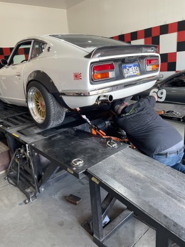
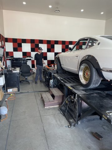
08-07-2025. DYNO morning. Found out a couple of things. 7 psi in 3rd gear WOT at 5500 RPM, 9 psi in 4th gear WOT 5500 RPM. She is RICH....rich to the point of fuel popping, 10.0 to 1, A/F rich, and didn't want to go past 5500 RPM (strange since on the road she will but nevermind). So, there is probably 40 horsepower left in her in the DYNO guys mind. We made 4 runs, and in 4th gear without using any Water/Methanol injection, it pulled 196.8 hp at the rear wheel, at 5500 RPM and at 18% drive train loss that is 232 hp at the crank@5500 RPM. Torque was 268.3 at the rear wheel, 316.59 at the crank@ 5500 RPM. Boost was 9 psi at 5500 when he had to let out because it was so rich. We did a run in 3rd gear WITH water/Methanol and it pulled 226.7 hp at 5500 RPM at the rear wheel, so 267 HP at the crank@5500 RPM and 260 torque, which is 306.8 TQ@5500 RPM, boost was 7 psi. So, as I thought when building it, the stroker and the stock cam made it into a torque monster. well over 300 ft lbs. torque, 232-267 horsepower.....but it is PIG RICH. So, power is limited by being rich. I have dyno charts, but the RPM range at the bottom is all wrong. we weren't able to get to 6000 RPM because of the rich condition. He said it was basically 10 to 1 A/F on the runs, which is WOT, so the main jet is just too big. I can step it down one. As expected, the carb is the limiting factor. I will post the dyno sheets, but as I said the RPM range at the bottom is wrong. he let off at 5500, I wanted 6000 RPM but he said it just wouldn't do it., when he let off the throttle the unburned fuel was popping and banging. Pics follow (video at the end). V1.MOV
-
In doing a V8 swap, are you able to hook up the factory speedo cable to a GM trans? I guess there is a box you can install to get the factory tach to work. Can't think of the name right now. Thanks.
-
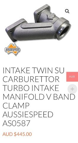
Aussie Speed has a dual SU intake for draw through turbo setups. This intake would also allow for dual Mikuni HSR bike carbs as well!
-
Fast Floridian's 240Z Track Build
A to Z replied to FastFloridian's topic in S30 Series - 240z, 260z, 280z
sure is a different looking dash! -
My Z car log....small jobs done and fun things
A to Z replied to A to Z's topic in S30 Series - 240z, 260z, 280z
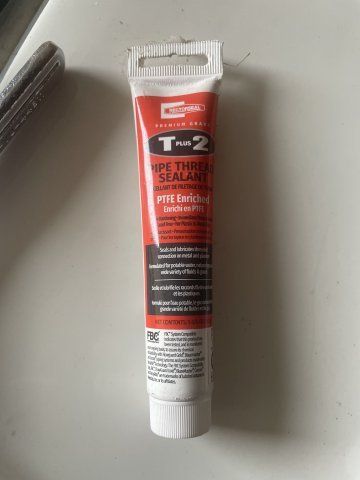
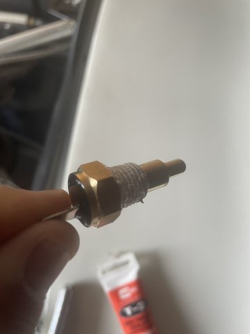
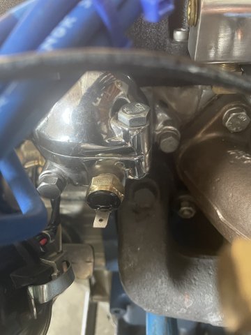
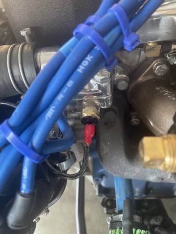
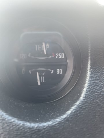
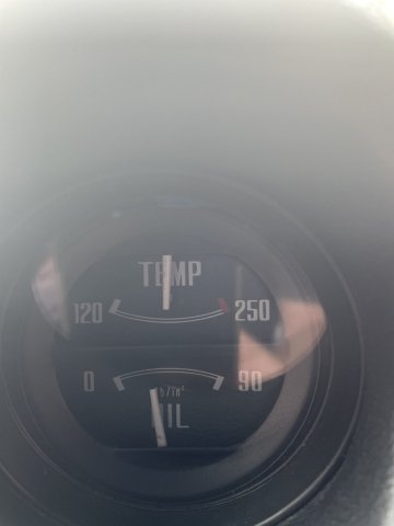
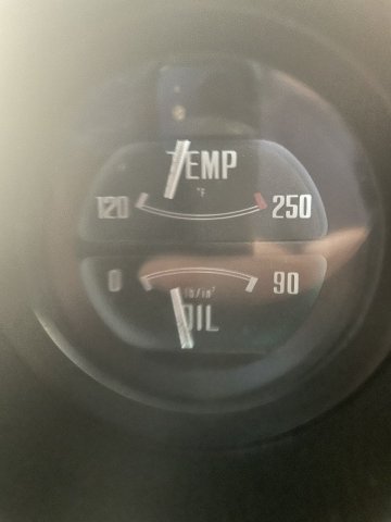
08-02-2025. My thermostat probe arrived, and after a bit of thread sealer I installed it and crimped on the end to finish that job. then I FINALLY got my new speedo cable screwed on to the back of the speedo. IT WORKS! In testing out my fan, I took 3 pictures of my gauge you see below. The first one is where the fans turned on, between the "M" and "P" on the word "TEMP". The second is what the fans pulled it down to , and the third page is where the fans turned off when I had turned the engine off and the fans were running....when they stopped I ran and took this pic, so don't fret about the oil psi looking low as the engine was off! I also have 3 videos at the end of the pics, just walk around type pics. So I can really say it's done. I did the car twice before this, and then the turbo install which turned into a MAJOR undertaking. Was it worth it? Yeah, but I didn't know how deep the rabbit hole was going to be when I started.....if I had I may not have done it, but what is done is done. With a draw through turbo setup like this, you have to have an "educated" foot, gradual on the adding power and removing power unless you are over 3000 RPM. That is the way these are, or at least the way mine turned out. I know the instances where it will go lean for about 1-2 seconds in certain accelerating situations, and hitting the Water/Meth injection right then smoothes that out. I think a small block Chevy (with dual 4 barrels & a nice cam) would have been way easier than all this, but maybe keeping this an L series makes the car more "neat", I don't know. Anyway this my Z car, version 2.5 V1.MOV V2.MOV V3.MOV
-
My Z car log....small jobs done and fun things
A to Z replied to A to Z's topic in S30 Series - 240z, 260z, 280z
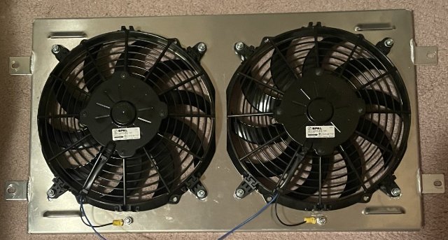
pulled from heat soak to almost midrange in under 10 minutes, sitting still, no additional airflow. SPAL fans are #1. Yes, it is a 3 core aluminum radiator, and a 160 thermostat, but it got heat soaked, and my twin 10" SPAL fans pulled it back down. -
My Z car log....small jobs done and fun things
A to Z replied to A to Z's topic in S30 Series - 240z, 260z, 280z
92 degree day Click below to see video: 07-27-2025.MOV -
My Z car log....small jobs done and fun things
A to Z replied to A to Z's topic in S30 Series - 240z, 260z, 280z
07-26-2025. Okay....radiator and fans installed and working. Waiting on the Thermostat sensor probe that is on it's way. 1 bottle of Water Wetter added. click below for video: fans work.MOV
-
My Z car log....small jobs done and fun things
A to Z replied to A to Z's topic in S30 Series - 240z, 260z, 280z
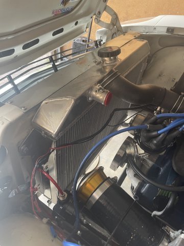
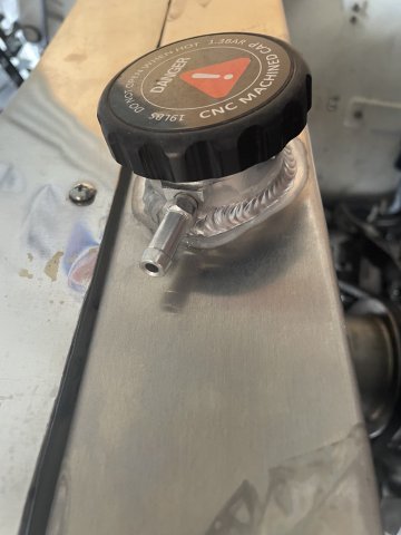
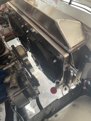
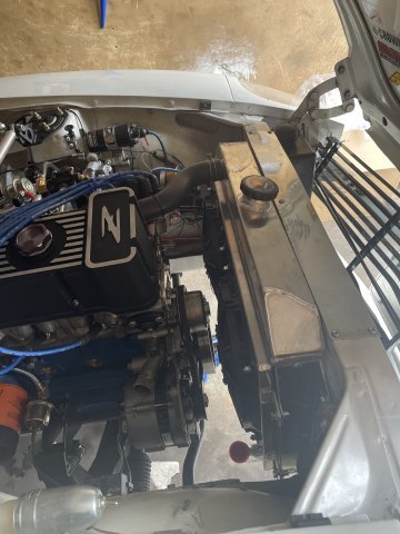
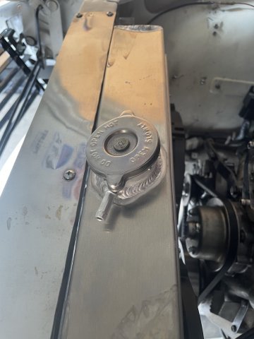
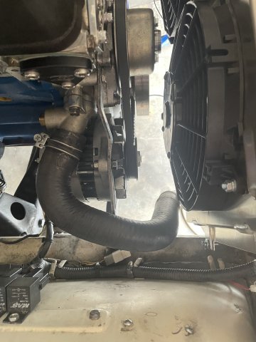
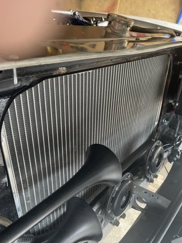
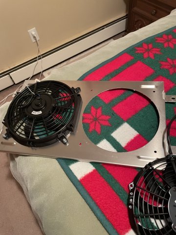
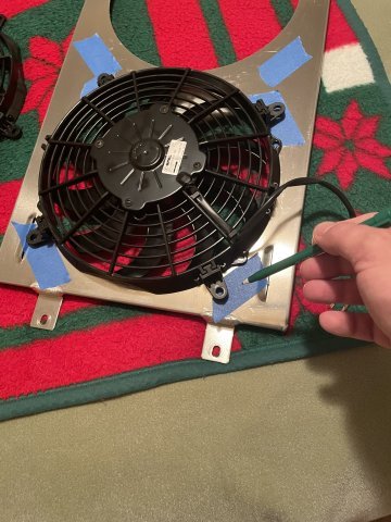
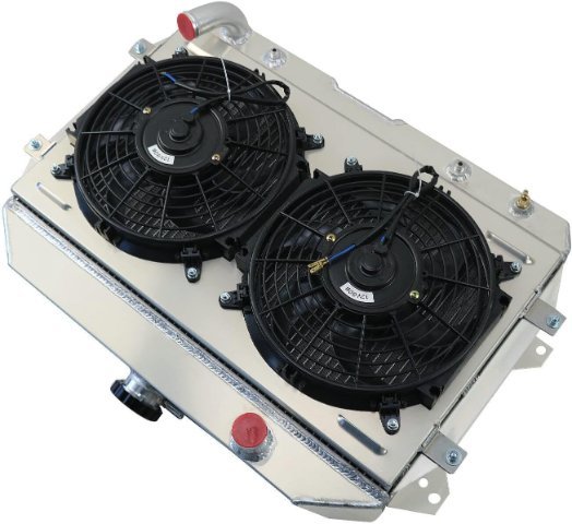
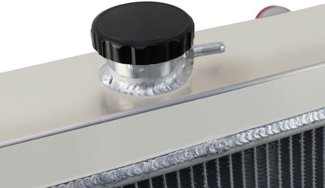
07-25-2025. I had a couple hours today, so I decided to see if the radiator would bolt in. Since June of 2021 I have been building my Z car. This is FIRST aftermarket part EVER to bolt right in. I didn't have to mod it at all. I was speechless. Granted, swapping the fans out to the SPAL fans required drilling and playing with it to get it done. However, I was able to drop the radiator and the fan should assembly right in. It is still loose, but it is there, hoses on, loose, but the idea today was......with a little time to see how far I could get it together, it literally just fell together. So "cubauto" on Amazon, there radiator for our Z cars goes right in! Now, the overflow tube on the cap was put on crooked, so I have to live with that, that is the only negative in an overall very nice looking package. Because of the size of my remaining port on the thermostat housing, using a sensor to turn the fans on and off isn't going to work. Being that my Z is just an around town toy, I will be turning the fans on and off via toggle switch. The remaining switch is 20A rated, but I ordered a switch that externally looks the same but is 30A rated to swap in. I will be feeding both fans with 10 gauge wire which is 30A rated and will forgo using a relay. 30 fA use and it will be basic, clean, and work. I swapped out the 19 lb radiator cap for the facotry 13 lb one for now. Pics follow. Good few hours today! Cheers!
-
My Z car log....small jobs done and fun things
A to Z replied to A to Z's topic in S30 Series - 240z, 260z, 280z
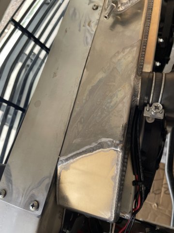
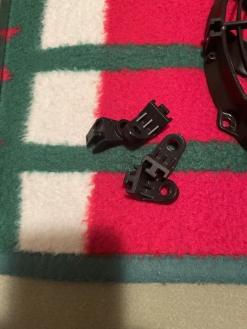
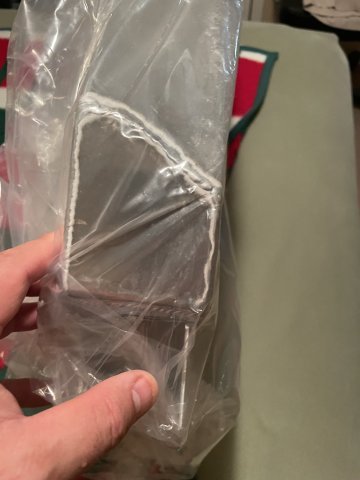
shroud complete and ready to go~!
-
My Z car log....small jobs done and fun things
A to Z replied to A to Z's topic in S30 Series - 240z, 260z, 280z
-
My Z car log....small jobs done and fun things
A to Z replied to A to Z's topic in S30 Series - 240z, 260z, 280z
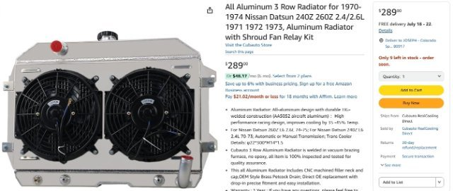
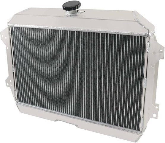
Radiator arrived:
-
Help me evaluate this car for sale
A to Z replied to z_noob's topic in S30 Series - 240z, 260z, 280z
Buy the nicest one you can afford. Trust me. -
My Z car log....small jobs done and fun things
A to Z replied to A to Z's topic in S30 Series - 240z, 260z, 280z
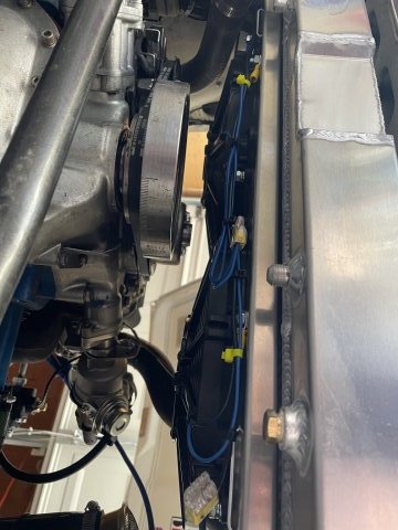
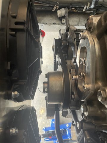
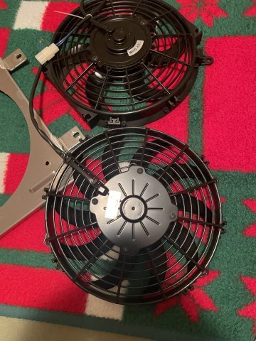
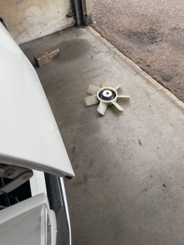
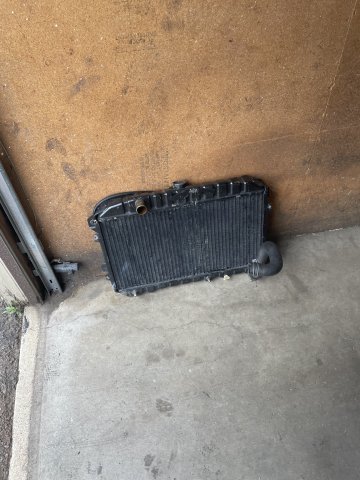
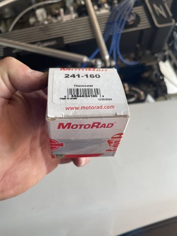
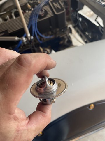
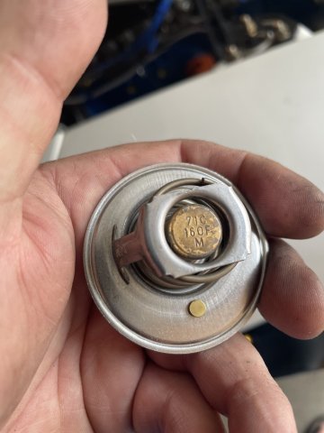
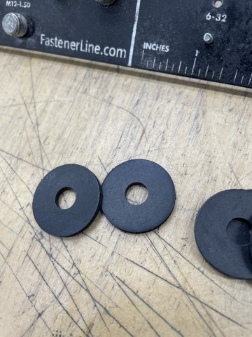
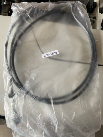
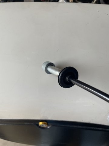
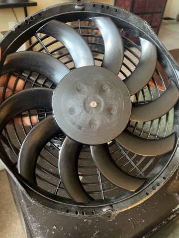
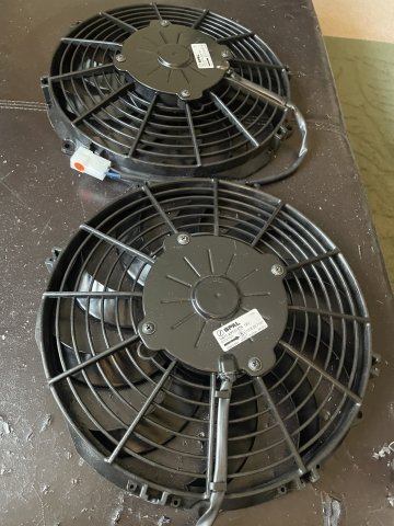
07-19-2025. Well today was a day to get the car ready for it's updated radiator and fans, and do some other small work. I took both SPAL fans and tested them to ensure they work and that they spun in the right direction. Then I began the process of pulling the radiator out. I found that I needed some different bolts for the water pump pulley, and so while there I went ahead and got all new hardware for the radiator when it gets here. I bought some thick rubber washers to isolate the aluminum radiator fromt he car, to keep corrosion of the radiator at bay. After that I swapped out my radiator thermostat from the factory 180 temp to a 160 temp and then installed a new Speedo cable. I spent a little more and got one from the Z car Depot, partly because it comes with a new firewall grommet. Ready for more new parts to arrive! PICS:
-
My Z car log....small jobs done and fun things
A to Z replied to A to Z's topic in S30 Series - 240z, 260z, 280z
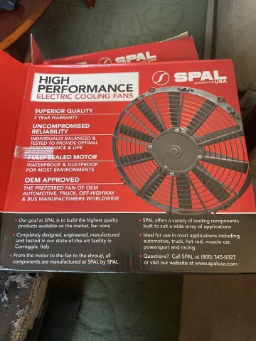
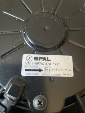
My SPAL fans arrived today:
-
My Z car log....small jobs done and fun things
A to Z replied to A to Z's topic in S30 Series - 240z, 260z, 280z
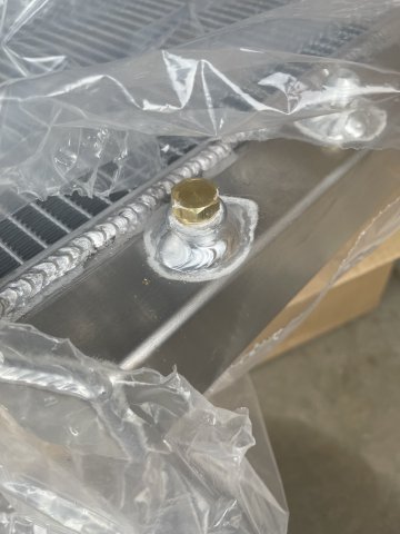
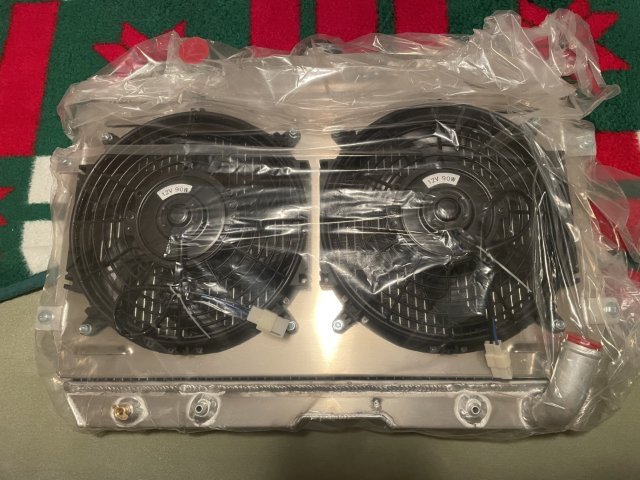
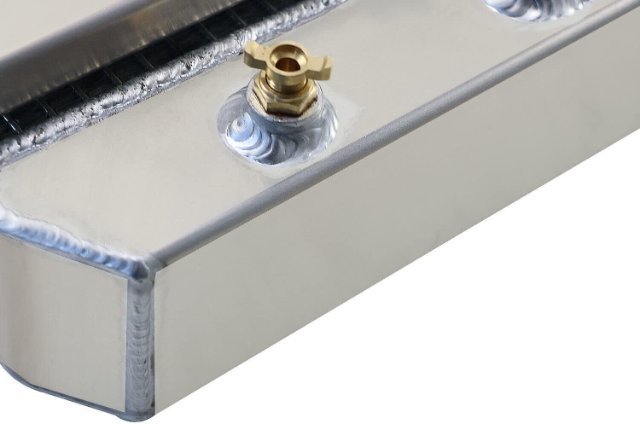
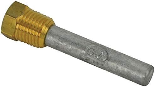
So, the heat issue has caused me to go ahead and order a 3 row aluminum radiator with dual electric fans. I decided to get one I found on Amazon, made by CB Auto - which is in CHINA. So, half price of others and looks to be okay. I also went ahead and got an anode made of zinc that screws into the drain petcock. This is what allows the minerals to attack it instead of the aluminum in the radiator. I also will be switching my thermostat to a 160 degree one I ordered. Since I have had good luck with the chinese parts I have used, we will do this. factory video, click here: https://www.amazon.com/vdp/048db201f503475ea5ee22731531c6e1?product=B0BQGTGGL4&ref=cm_sw_em_r_ib_dt_8D3hq5NBWLJy6
-
Reach out to Eichi at Datsun Spirit. He is on your side of the country. click: Home | Datsun Spirit, Inc. - Datsun Parts, Engines, Restorations.