clarkspeed
-
Posts
878 -
Joined
-
Last visited
-
Days Won
49
Content Type
Profiles
Forums
Blogs
Events
Gallery
Downloads
Store
Everything posted by clarkspeed
-
240z SCCA vintage race car, restoration
clarkspeed replied to AydinZ71's topic in S30 Series - 240z, 260z, 280z
That is a beautiful install. My experience with bars is I usually use about a 3/4 hole spacing on adjustment. I start with front light setting and try to induce oversteer. Then gradually stiffen front until it disappears. If you can't get oversteer, then reduce bar size. If you run f/r bars you obviously have 2 choices on adjustment. Once I adjust past that oversteer threshold I stop. 3/4" hole spacing on the arms is actually a fairly large change in spring rate. It's a simple math equation to check this. A blade style adjuster gives an infinite adjustment but I have never driven with one and not sure if the cost is justifiable. -
240z SCCA vintage race car, restoration
clarkspeed replied to AydinZ71's topic in S30 Series - 240z, 260z, 280z
He'll yes, looks amazing. They didn't even disturb the anodizing. -
240z SCCA vintage race car, restoration
clarkspeed replied to AydinZ71's topic in S30 Series - 240z, 260z, 280z
Man don't try that. As soon as you start jacking and hear it creaking you will think man this thing can kill me fast if something slips. I get scared pressing bearings sometimes with a sketchy socket jammed in there. You could probably design some tooling to make it safe, but that will also be a hassle. I'm still thinking sledgehammer with it secured to something solid. Unless you can find a way to bend the aluminum, I think you have 3 options and they all involve a steel arm. 1. John's welded up arm with a splined steel stub cut from another arm. It's a real cool idea. Another take on this is the Speedway Motors stubs. They are pretty cheap and you can weld to them. This is what I used in rear of mine. https://www.speedwaymotors.com/Complete-Torsion-Bar-4130-Rear-Arm-Kit-1-Inch,2141.html They sell just the stub in a few 48 and 49 spline sizes. The pipes are rather large and a little heavy, but they fit up perfect on rear of mine. The stub is quite heavy also, but that can be fixed. 2. Get a steel arm and apply torch. From what I can gather, most every circle track car does this. 3. You might be able to find a steel and maybe aluminum arm already bent. Google offset sway bar arm and you can find some new options. Sprint car guys call them torsion bars. And I bought the set for my last car off of eBay. They come up often for sale used but it can take some time to find a matching pair the right size. -
IMSA GTU vintage racer build
clarkspeed replied to clarkspeed's topic in S30 Series - 240z, 260z, 280z
It looks like it will work so far. Everything is a compromise. The longer the arms are, the more leverage is applied. Which means heavier bar to resist. Spring rates are tricky. That is where I digress from Greg. I think I can engineer this "new" car or any new race car to about 90% of where it needs to be. I am confident on what all the measurements should be. And I know exactly how to test to improve. Greg comes from 20 years of testing every damn combination you can think of on a Z car and has a fixed formula that is 98% there for a S30 chassis. But being perhaps an old but still naive engineer, I am using a somewhat blank sheet of paper., I am taking everything I know, plus improved version of everything I know he runs, plus everything I can improve for control, ergonomics, grip, low Cg, efficient aero, driver comfort, weight savings, and applying to a much looser rule book. Best part of it all, Greg will get to evaluate at some point. And hopefully co-drive somewhere if I get comfortable with reliability. But my car is not a no compromise or all out build. It still has a very strict budget limitation and has hopefully "smarter" solutions rather than money is no object. -
IMSA GTU vintage racer build
clarkspeed replied to clarkspeed's topic in S30 Series - 240z, 260z, 280z
Yes I have a rear bar. It is in my thread somewhere. Reasoning is my Z is pretty far from a stock unibody and should be a stiff enough platform. I plan to control roll a little more aggressively with bars than my other builds. Relatively medium to stiff springs with no rear bar and a light front bar is a proven combination on S30 Zs. Science will tell you lifting a front wheel on corner exit is lost traction, but getting power down earlier can compensate for that. When all is balanced, it just works and makes for benign handling at the limit. If you are unsure of spring rates and sway bar rates on your build I may be able to help. Or if Greg gives you something, you can run with that. His recipe based on vast testing experience. -
240z SCCA vintage race car, restoration
clarkspeed replied to AydinZ71's topic in S30 Series - 240z, 260z, 280z
Your solution is valid. You don't need a lot of support around that bearing.. many of the comments above reference putting a standard "clamp" bearing to the stock frame rail, which is a little sketchy, but a reinforcement plate solves that. And the aluminum heating info sounds like what I researched. That is how I ended up thinking about a sledgehammer. If you read the internet, you will find various opinions recommending steel arms due to flexing. That all depends on how stiff/thick your bar is of course. I figured my bar is not 400lb or above so I opted for aluminum and 3/8 rod end arms. I will put a camera in there at some point during testing to watch it. So in the end I think press is the best way to bend them. But my un tried sledgehammer should work also. -
IMSA GTU vintage racer build
clarkspeed replied to clarkspeed's topic in S30 Series - 240z, 260z, 280z
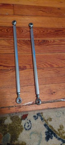
My long ass 14" end links came today from Coleman.
-
240z SCCA vintage race car, restoration
clarkspeed replied to AydinZ71's topic in S30 Series - 240z, 260z, 280z
That sounds about right since I just bought the same. I got my bar used on Ebay and built my own bearing bearing holders to save a few bucks. But compared to other options it's really not that bad. I just got my end links and will post on my page. Let me know how you bend the arms. I wasn't sure heating the aluminum would be good..I thought about putting mine in my press but that scares the hell out of me. I was just going to brace them and hit with a sledgehammer. But with my new mount it doesn't look like I will need to. -
240z SCCA vintage race car, restoration
clarkspeed replied to AydinZ71's topic in S30 Series - 240z, 260z, 280z
Man you get things done before I can even post examples for you! Greg runs a bearing like you selected on all his cars. Those end links should be fine. With the straight arms you may need to mount a little higher to try and keep them close to parallel. I think Greg runs the 30 degree. -
240z SCCA vintage race car, restoration
clarkspeed replied to AydinZ71's topic in S30 Series - 240z, 260z, 280z
-
IMSA GTU vintage racer build
clarkspeed replied to clarkspeed's topic in S30 Series - 240z, 260z, 280z
Boxed sheet is probably the way to go.. I went with aluminum arms. I'm not sure that is the best answer, but similar to you, I may come back to that another day. I have with steel stubs with a cr- Molly bent pipe in the rear and that worked pretty well. Another place I may stick a camera when testing just to see what is going on. But not a lot of real estate available if I want to change it up. -
240z SCCA vintage race car, restoration
clarkspeed replied to AydinZ71's topic in S30 Series - 240z, 260z, 280z
My recomendation is a multi piece bar from Speedway Engineering like your picture. Reasonably priced and more importantly, you can swap out bars of you need to. Plus you can find them used on ebay depending in the size. I would not try to lengthen one or bend one myself. On the other hand,, I would not be afraid to weld on some angle iron brackets or similar to the existing OEM style bar you have if that can make up the difference. OR an offset bracket attached to the control arm.. I have some examples if I can dig up the pictures. And yes, adjusters and rod ends for the links. -
240z SCCA vintage race car, restoration
clarkspeed replied to AydinZ71's topic in S30 Series - 240z, 260z, 280z
Yes, yes, and yes. I have a big surprise reveal for my struts. But you will need to wait for that. -
IMSA GTU vintage racer build
clarkspeed replied to clarkspeed's topic in S30 Series - 240z, 260z, 280z
You got it. They sway bar sits in needle bearings inside the 3" tube. A circle track style. The arms need to be cut about 6" and drilled for adjustment. I ordered the heim joints and links to finish out. It sits about 1" in front of the head if my measurements are correct. The pics are so damn busy I can't even tell what's going on. Anyway the tube bolts to the strut towers and the frame rails. -
IMSA GTU vintage racer build
clarkspeed replied to clarkspeed's topic in S30 Series - 240z, 260z, 280z
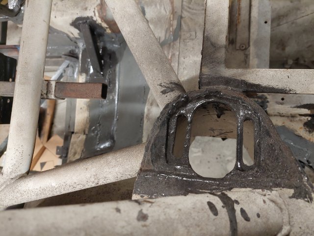
I am a little behind on my posts. Pushing to finish most of the serious welding so I can take it off roterssere. Here is a shot of the front sway bar attach. I was not comfortable placing it under the frame for interference and did want to go through the frame. So this is where it ended up. I didn't like putting the weight up so high so I tried to steal as much rigidity to the front as I could with it. The cross member comes very close the the head and unbolts for engine swaps. Sure looks like a GT car now. Sorry the top pic is upside down.
-
240z SCCA vintage race car, restoration
clarkspeed replied to AydinZ71's topic in S30 Series - 240z, 260z, 280z
Looking good. You are so far ahead of me on the front. I am still in the roterssere for a few more weeks until I can access that area. I am also adding 4 tie downs to the underside of mine for strapping to the trailer. It makes hooking and unhooking so much faster. I do that on all my cars. -
240z SCCA vintage race car, restoration
clarkspeed replied to AydinZ71's topic in S30 Series - 240z, 260z, 280z
That looks damn sturdy. Nice work. Some use 1/4 or 3/8 round steel for supports just so you can adjust a little with a big lever/hammer. Yours looks beautiful and light weight also, AND very exact. -
IMSA GTU vintage racer build
clarkspeed replied to clarkspeed's topic in S30 Series - 240z, 260z, 280z
I have GC bolt in plates for the front. I found a universal set on ebay couple years ago. I like their plates best, but they are kind of overkill for rear. The rear actually use the original mounting plate. I just cut it out to match my homemade slider. I wonder if this is considered "bolt in"? No more hacking than cutting out for a set of bolt in plates. Best is to somehow go by all the original holes and reference points. The FSM has a chassis layout drawing with all dimensions. Try to get the chassis as level as possible F/R and L/R. Layout tape or paper on the floor and use plumb bobs to mark points like the strut tops. That will allow you to check all the X and Y dimensions and cross chassis square. And I use a digital level to measure stuff in the Z direction where I can. Across strut tower tops, front cradle, etc. -
IMSA GTU vintage racer build
clarkspeed replied to clarkspeed's topic in S30 Series - 240z, 260z, 280z
Just homemade camber plates to save a buck. They don't get as much use as the fronts. These are the holes they slide into.
-
IMSA GTU vintage racer build
clarkspeed replied to clarkspeed's topic in S30 Series - 240z, 260z, 280z
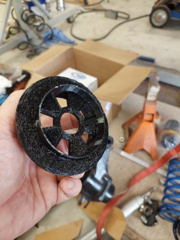
Oh and here is my 3D printed drivers side door handle. -
IMSA GTU vintage racer build
clarkspeed replied to clarkspeed's topic in S30 Series - 240z, 260z, 280z
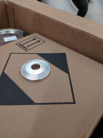
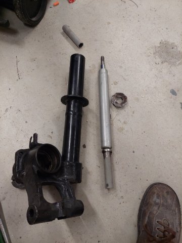
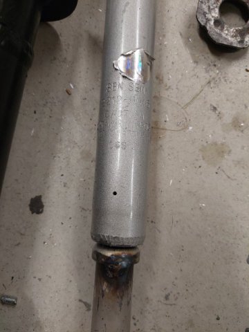
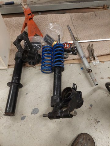
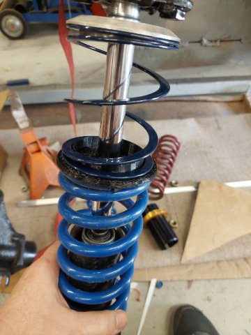
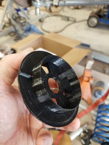
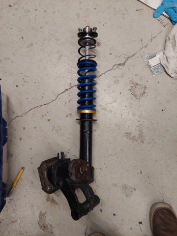
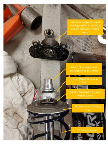
Sorry have not posted in some time. Been busy making my own brake rotor hats. More on that in a future post assuming I am successful. These posts are now basically caught up with where I am at on the build. Most of the stuff I will be posting from here on out will be relatively "fresh". So here is the rear strut build up. The struts are from a 280 and shortened. The cartridges are a cheap no-name brand I bought off of Rock Auto a few years ago just for fit checks. I just welded a spacer on the bottom so there is no chance of it not seating correctly. I 3D printed the spring spacers and milled a button top for the spring hat to fit a thrust washer in there. The camber plate is also made by me with a 5/8 spherical bearing.
-
New to the forums. Looking for insight on what to do.
clarkspeed replied to Zellthetunerr's topic in S130 Series - 280ZX
Old wiring is a pain in the ass. Look first at all connectors for corrosion, the wires are probably OK if not modified. Do not assume anything is getting signal, voltage, ground as it should be. Always start with the simple stuff, then work toward the more difficult, like point to point continuity. I once had a fuse that looked fine, had continuity, but would not take any current. Lesson learned, verify the simple stuff first and I mean verify. Someone posted some good detail on this recently. The Bosch L-jetronic is a very simple system. Not many inputs or outputs. When everything is working as it should, it is bullet proof and fairly easy to troubleshoot. It can even be adjusted slightly for mild modifications. If you can troubleshoot components per the factory manual, you are way ahead already. As you can tell I am a big fan of these original systems. I played with them for years. One of the favorite Zs I have owned was a 80ZX with big throttle body, ported 76 intake, mild pocket porting on the head, 6-2 headers with 3" exhaust on stock efi. Otherwise stock. Something about the sound, rear end squat, and flat torque curve just worked right. But I will also never forget chasing that damn fuse problem for 2 weeks. Or the time the heater hose had leaked on a connector and corroded it and I did point to point checks for 2 weeks, and the time.....old cars are tough. -
Very nice car!
-
240z SCCA vintage race car, restoration
clarkspeed replied to AydinZ71's topic in S30 Series - 240z, 260z, 280z
The standard 1/4 turn are easy to find. I don't recommend buying from Speedway, those are made a little too thin. I learned my lesson there. I buy the Panel-fast from Brehents. I use them to secure all my body panels. I think the camloc's are a Euro aerospace thing for interior panels. A lot of aircraft companies sell them. I can't remember who I bought them from last time. These guys seem to have similar. The adjustable receptacle is nice if unsure of panel thickness . https://sri-supplies.com/ -
240z SCCA vintage race car, restoration
clarkspeed replied to AydinZ71's topic in S30 Series - 240z, 260z, 280z
I had to Google quick latch. I call those button latches. I used them in my passenger door. Greg uses 2 locking Aerolatch on hood of the EP car. He said people may sabotage car at runoffs. FYI you can get the quick/ button style latches super cheap direct from China. I use true military grade cam lock fasteners on my back hatch. We used the same when I worked in aerospace on space shuttle. They are expensive but small and strong. And damn they work well. I have 4 butterfly camlocks on the back hatch. Plenty strong enough for hood too, but kind of small to fiddle with flathead screw type if you are in a hurry. And I did not think the butterflies would look good there, even though they are tiny. Again, quick and easy to remove/install panel and they align quickly. My crew loves my hatch and hood solutions. A hood that slides into something at the firewall and has 2 button latches in front would be fastest to remove/install of all. It is amazing how critical an interface the hood and hatch are. It is inevitable your crew or yourself will be trying to closeout these spaces as fast as you can go. Quick positive lock with no error is so important. 4 hood pins with cotter pins doesn't cut it.