-
Posts
877 -
Joined
-
Last visited
-
Days Won
47
Content Type
Profiles
Forums
Blogs
Events
Gallery
Downloads
Store
Everything posted by clarkspeed
-

IMSA GTU vintage racer build
clarkspeed replied to clarkspeed's topic in S30 Series - 240z, 260z, 280z
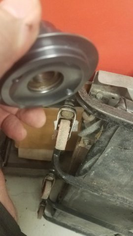
I have been using these Mazda throttle body flanges for brake cooling ducts. I found them on amazon super cheap. They are cast aluminum and I just drill them to fit the holes for the OEM backing plates. -

IMSA GTU vintage racer build
clarkspeed replied to clarkspeed's topic in S30 Series - 240z, 260z, 280z
Wow I missed out on posts for the last couple days. Some interesting techniques I need to try out. I tend to use very thin sheet to fill body panels, sometimes even thinner than the Datsun panels. No gap, low heat, and typically a "pearl necklace" finish like you mentioned. Although I would never use that phrase. I always check the back side for overall good pen, but not every mm, grind to finish, and then thin bondo along with a backside coating. I rarely hammer the welds or shrink metal, just smallest negative profile I can attain (less than 1/8"). Small pinholes everywhere. But keep in mind, I build race cars, not show cars, so I'm not to concerned about getting an all metal flat finish like the guys do on TV. As long as I can duplicate the contour, no one will ever check it with a magnet. Race cars always stay indoors, and tend to be repainted often. I've never had a bondo crack or rust break through, without direct contact of course , -

IMSA GTU vintage racer build
clarkspeed replied to clarkspeed's topic in S30 Series - 240z, 260z, 280z
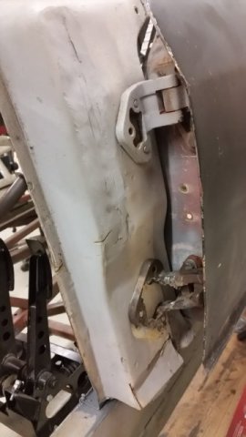
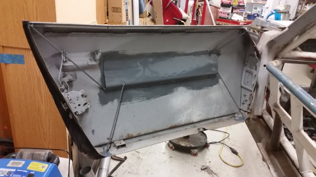
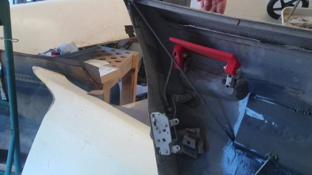
And here is the driver's door. Car came with the door fully cut out and it was floppy. I have seen these wrinkle up on other race cars and God forbid if someone accidentally leans on it. Anyway the cage sits very close to the skin, so I got creative with a some bent sheet metal and 3/16 rod. It is as rigid as a complete door now. The upper hinge was milled out, but I ended up blasting out the lower hinge with my $400 plasma cutter. I added a 3D printed inside door handle. I can sell these if anyone is interested. -

IMSA GTU vintage racer build
clarkspeed replied to clarkspeed's topic in S30 Series - 240z, 260z, 280z
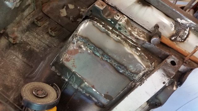
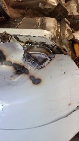
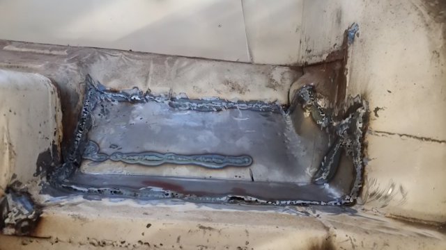
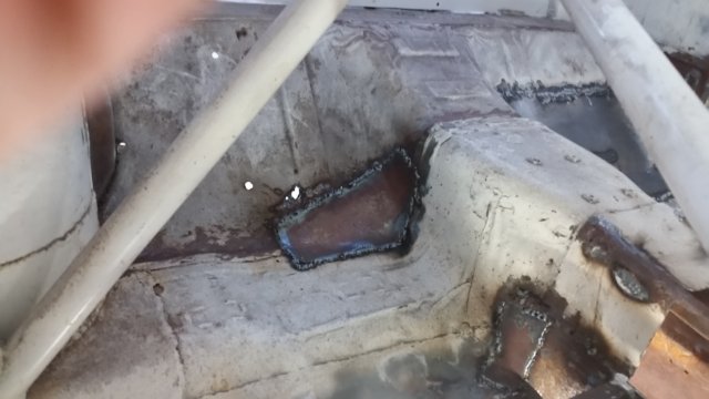
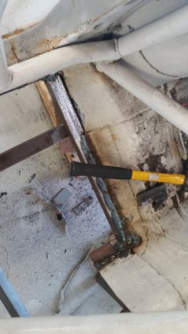
Maybe this gives a little sample of just how rusty this tub was. These are some of my repairs along with patches over previous repairs. Please don't comment on some of the poor welding. Many of the welds were not clean on the backside and these are not structural. If you notice, I cut out the entire storage box area. I have the weight savings written down somewhere if I can find it. -

240z SCCA vintage race car, restoration
clarkspeed replied to AydinZ71's topic in S30 Series - 240z, 260z, 280z
I measured my Sweet steering shaft. It looks like 28 collapsed and 34 extended. And that includes the steering wheel QD spline on the end. Like I mentioned, it is just a little on the long side . I would say 25 to 26 collapsed would be optimum. I also use a flat steering wheel. If you use a dished or deep dish steering wheel, take that into account. -
Great job on developing this! I am considering for a road race build. But have a couple questions. Strength is not a concern for me since I can make it fine with an R180 and u-joint axles. But I like this option due to cheap parts availability and virtually unlimited ratios. Weight is a concern. A R180 is a little over 60lbs and an R200 is just over 70 dry. Best I can tell the Ford 8.8 is 65 in aluminum and 85 in iron. Does that sound right? If so that is a pretty simple trade off. Do you know how much your cradle and uprights weigh? The cradle is a weight adder, but it looks like the uprights could be a reduction. Thanks for your attention.
-

IMSA GTU vintage racer build
clarkspeed replied to clarkspeed's topic in S30 Series - 240z, 260z, 280z
Not sure on the length, I can measure it next time I am at the shop. It is a little on the long side because I need to collapse it quite a bit when installed so it only leaves a couple inches of "crush" zone. I will also try to get an estimate of the weight. It is a solid steel rod. Greg's EP car is refined to a point. He spent probably 20 years developing it. He doesn't make any more major changes to it and uses a similar formula to build other cars for himself and customers. However it is surprising how much OEM stuff he uses and simple common off the shelf parts. -

IMSA GTU vintage racer build
clarkspeed replied to clarkspeed's topic in S30 Series - 240z, 260z, 280z
The car is mostly cage, it has very little rigidity left in the tub. Between the rust and everything I have already cut out, I am more worried about panels wrinkling up than providing any structure. That is one of the reasons I have not cut it out yet. The front pillars are already tied to the cage, and it is connected to the rear main hoop above the side window. Vibration is not normally an issue on a car car. You tend to rev right through it. -

IMSA GTU vintage racer build
clarkspeed replied to clarkspeed's topic in S30 Series - 240z, 260z, 280z
I am pushing the CG down as low as I can go. Exhaust exits side so no problem there. Flat bottom floor all the way. I think it will work ok. I have been staring at that damn cross member for months. Started to cut it out couple weeks ago and declined. Do you think it weighs enough to make a difference? Looking closely at it, it didnt look like that much metal. I am also staring at the drip rails. -

IMSA GTU vintage racer build
clarkspeed replied to clarkspeed's topic in S30 Series - 240z, 260z, 280z
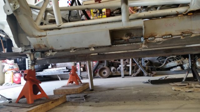
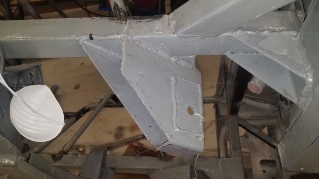
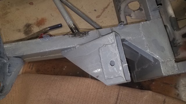
Next up is the floor and interior structure. I never noticed before until I started building this thing that the floor bottom on a 240Z is actually lower than the rocker panels. This car only came with rocker panels, nothing more. When I got ready to try and locate driver stuff I quickly realized that I couldn't just run a flat panel across the bottom. Turns out I needed to drop the floor roughly 1-1/2". Again all measured to the FSM datum points. So that meant building a frame around the tub. I used fairly thin square tubing since I already had plenty of structure above it. Again you can see the square tubing running fore and aft that represents where the bottom of the floor should be in relation to the chassis points. -

240z SCCA vintage race car, restoration
clarkspeed replied to AydinZ71's topic in S30 Series - 240z, 260z, 280z
In the tube car I am running a used Sweet column I got off eBay. I'm not sure it is that much lighter than stock. But it is adjustable and mounted with sphericals. Do the fit checks with the actual seat you will use. Usually end up as far back and as far to the center as possible. Then it's a matter of getting the rake to your liking. You can drop the steering wheel down but taller drivers will then bitch. But be careful of blocking yourself from getting in and out of car. One thing I did after moving the seat to the right was add some spacers under the flange at the bulkhead and slot the u-bolt more to kick the steering wheel toward the right. That always felt better to me than not having it centered. -

IMSA GTU vintage racer build
clarkspeed replied to clarkspeed's topic in S30 Series - 240z, 260z, 280z
Thanks for the offer. Yes I plan on getting a small lathe maybe later this year. I am forever needing a special bushing or spacer. I just got my home built CNC mill running and it seems to cut 6061 aluminum very well. This thing is so cool and opens up another world for me. I will cut these top hats as one of my first projects on it. Check out The MPCNC website from V1 Engineering. -

IMSA GTU vintage racer build
clarkspeed replied to clarkspeed's topic in S30 Series - 240z, 260z, 280z
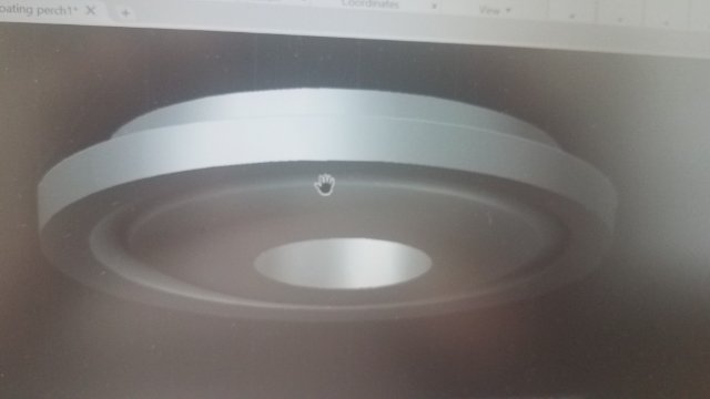
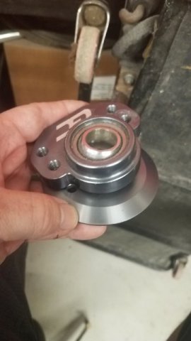
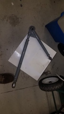
I sketched it up last night. This hat will ride in the radius "cup" shown previous so it becomes a hat on a hat. My hat has a generous hole to clearance the rod and I can cut down the outer diameter of the upper GC hat if I choose to make it look better. Picture shown is upside down. Now I just need to figure out how to cut it on my homemade mill. -

IMSA GTU vintage racer build
clarkspeed replied to clarkspeed's topic in S30 Series - 240z, 260z, 280z
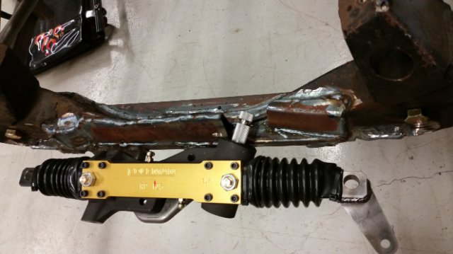
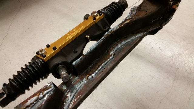
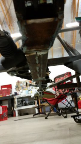
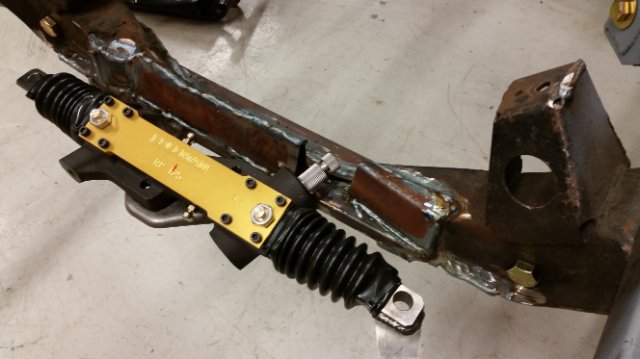
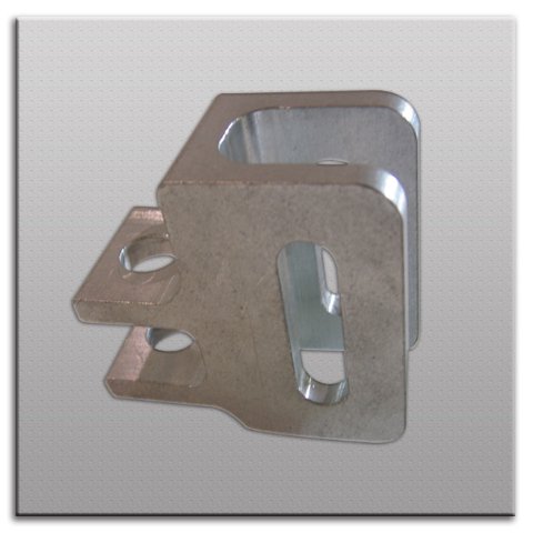
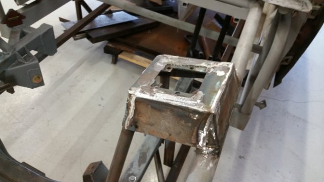
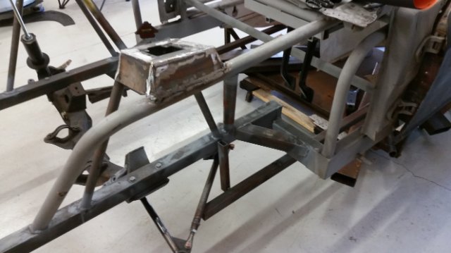
And on to steering. All of my OEM rack and pinions on the shelf had a dead spot and I thought this would be a good area to upgrade. I chose a Coleman Racing square rack in a ratio just slightly quicker than stock. But to use a circle track rack, I would need to widen the tie rod mounts to get the correct length, which should be equal to the control arm mounts. I search around the internet and found an adapter bracket design that I decided to copy. I designed a welded assembly made from waterjet cut mild steel that had the correct length and the slotted adjustment. Most rack manufacturers will tell you not to do this, but they like to make custom length racks also. I like the design because it will make eliminating bump steer very easy. As you can see, I had to do some surgery on the cross member to get access to the rack spline. -

240z SCCA vintage race car, restoration
clarkspeed replied to AydinZ71's topic in S30 Series - 240z, 260z, 280z
Well the fact that you are serious and seem to be a decent fabricator, most others will be generous with help. The dual MC's are only require slightly more pedal effort. And they are much easier to modulate. Clark -

IMSA GTU vintage racer build
clarkspeed replied to clarkspeed's topic in S30 Series - 240z, 260z, 280z
Jon, I took another look at my camber plates tonight. I seem to remember previous versions of my GC camber plates did incorporate some sort of spring adjustment. Anyway, after reviewing the plates and the Mustang plates, I will add a "floating" spring perch to fit with the GC plates to compensate for spring alignment. -

240z SCCA vintage race car, restoration
clarkspeed replied to AydinZ71's topic in S30 Series - 240z, 260z, 280z
If you can get a solid pedal box, I can show you how to convert it to a bias bar adjustable dual MC setup using the stock pedal. A fabricators "special". Tilton (or other) is also a good option if you dont mind fabbing a way to mount it. Greg is THE source for EP builds. Many of my earlier quotes are based on my experiences crewing for him. EP is a very specific class and very difficult to run at national level. -
The Winters style IRS is really trick, but not an inexpensive option. It is something I have considered. Too bad there are not a ton of used ones floating around like the 4 speed Jericho's. Mine has a super close ratio so first gear is useable and tops out at like 70mph. Should be a lot of fun driving around the pits! The cool thing about Daytona is all of the turns are around 50-55 mph min speed so if you have the right final drive, it works. I want to run the 24hr vintage race there to get that off my bucket list. You really have your pick of slicks with the 18's. Everyone makes those and wheels are fairly plentiful also. Do you know what your tire/wheel combination weighs?
-
[Holly Shiiittte. I have dreamed of this many times and realize your difficulties. On gear ratio, I am facing a similar problem. I have a Jerico 4 speed in the car I am building which is always 1:1 in 4th for those in the know. I am looking at multiple tire diameters but limited to 16 or smaller on rim. Smaller the better for weight. But Daytona is one of the tracks I must build for, and that is max speed whatever your car will do. So unless I can move to a 3.3 or lower gear or I will need to increase tire diameter. So I am thinking about a 26-27 tall 15" tire (think Nascar) or swapping a Ford IRS rear. Of course money is always an influencer. I have 3.5 and 3.9 R200's loaded with Quafe's ready to roll. So gear ratio becomes an issue for just 1 track. I am trying to find a way to run from 50 mph to 160 mph with the same tranny. That is really an accomplishment running 18" in competition. Looks like you adapted to the dog box very well in the video. I can accommodate most any tire size with my current suspension like you I may have some physical interference I need to watch for. I am most impressed with you recent changes. As I mentioned in a previous post, I am lucky to know some REALLY fast Z cars intamately. And your build is definitely pushing the envelope.
-

IMSA GTU vintage racer build
clarkspeed replied to clarkspeed's topic in S30 Series - 240z, 260z, 280z
Yes, already done, but never too late to rework. 😀 That is one of the reasons I started this thread, to get input on things done, and help with some future decisions. I ended up reworking the strut tops twice. I will show in a later thread. Instead of Z car camber plates, I ended up with a set of GC universal camber plates in front. They do have caster slotting similar to the Mustang plates you reference, but I chose not to use it for now. I can do some more slotting if needed. As far as spring support, that has not been designed yet. I only have the basic camber plates, so I will need to use a top hat and thrust washer of my own design. -

240z SCCA vintage race car, restoration
clarkspeed replied to AydinZ71's topic in S30 Series - 240z, 260z, 280z
Perfect -

240z SCCA vintage race car, restoration
clarkspeed replied to AydinZ71's topic in S30 Series - 240z, 260z, 280z
I am not sure I am following all your issues, but yes it is common to add a spacer under the strut cartridge to get the proper fit at the gland nut. I usually cut down some 3/4 pipe. And the tubes should be longer in the rear, hince a longer spacer used there. I thought the GC stuff was set up for 10" springs, but I have not used their coil over kit in awhile. Either way, the ultimate goal is to have the strut rod sitting at mid distance when static loaded. So if the Koni's have 5.5" travel, the rod is compressed 2.75" with static loading and you have max travel available in both directions. The GC directions are an approximation to get you close (hopefully enough). There are some good write ups in this forum from John C. -

IMSA GTU vintage racer build
clarkspeed replied to clarkspeed's topic in S30 Series - 240z, 260z, 280z
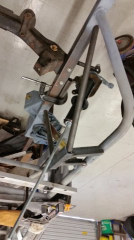
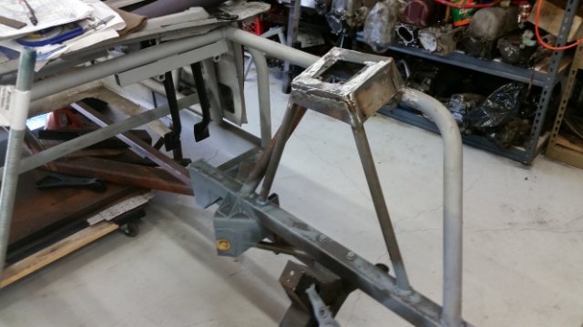
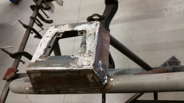
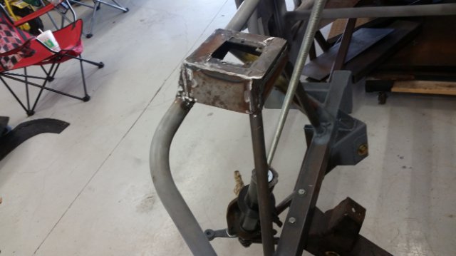
So to build up the upper strut mount, I started with a 1” angle assembly that would hold camber plates. I measured out the Ground Control camber plates I had installed on my other car arranged the angle in such a way to hold another set of them. Then it was a matter of locating this bracket in relation to the lower control arm pivots. This was another critical decision, location of the strut tops affects the caster, camber, and shock travel. So I set up an empty stock strut with a threaded rod substitute. I attached it to the lower control arm and set the caster right around 6 degrees. I have successfully ran 5 degrees before using an adjustable t/c rod so I know this will work. John C on this forum stated 8 degrees was good target, but that seemed a little extreme. Anyway from 6 nominal I can get to 4 or 8 without too much problem if I want to experiment with it. So in the end I located the strut top with a 6 degree rake, at a height I thought similar to stock, and at a width a little more narrow than nominal for future camber adjustment. So essentially a 3 dimensional placement in thin air. This will not be the first time I will need to locate a a part 3 dimensionally in thin air. Fun stuff when all of your reference points are 2, 3, or 4 feet away. -
Damn you Ben280, you made me go back and read this entire thread again! How did you make the conversion to 18"? #1 - What did you do for gearing? Change tranny ratio's or diff? #2 - How did you deal with roll center, did the front and rear strut mods above get you there? BTW this thing is a beast! Really nice build.
-

IMSA GTU vintage racer build
clarkspeed replied to clarkspeed's topic in S30 Series - 240z, 260z, 280z
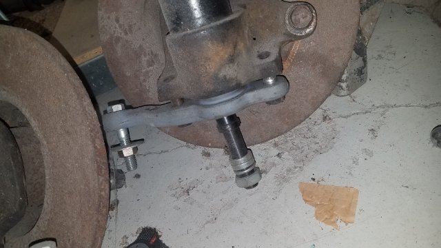
After the frame rails and cross member were located, I had my simple front control arms welded up. I had these tig welded by a friend due to the tricky multi thickness weld. I took measurements again from the shop manual and stock components. I used a spherical bearing and holder from UB Machine as the lower ball joint. This was combined with a monoball pin also from UB. I used a taper reamer from Speedway Motors to ream out the stock steering knuckle for the taper to fit. It you try this, be very careful the cast iron steering knuckles cut very fast. Go slow and measure the depth as you go. I tapered just enough to have thread engagement so a nut and washer do not bottom out. I also had to cut just a little clearance for the nut from the TTT bump steer spacers which are roughly like 1.5” long. The chrome molly tubing has 5/8 welded tube ends. I built a small tool using aluminum tubing and sheet metal screws to set the rod ends and angle of the control arm exactly as the stock configuration. I then adjusted the rod ends and locked them down so I could use the control arms as a tool to locate the T/C pickup point and the strut tops. Also of note, the rear T/C rod end pivots at exactly the same place as a stock one. So if you are paying attention, I have the roll center located lower by the TTT strut extensions. In addition, I can lower the outer ball joint. So no matter how low I go, I can still put the roll center exactly where I want it. And I also considered that the ball joint pin might actually interfere with the 15” wheels I will be running. If that is the case, I will slot the cross member and rear mount to move the inner pins upward, but I don’t think I will need to.


