clarkspeed
-
Posts
878 -
Joined
-
Last visited
-
Days Won
49
Content Type
Profiles
Forums
Blogs
Events
Gallery
Downloads
Store
Everything posted by clarkspeed
-

IMSA GTU vintage racer build
clarkspeed replied to clarkspeed's topic in S30 Series - 240z, 260z, 280z
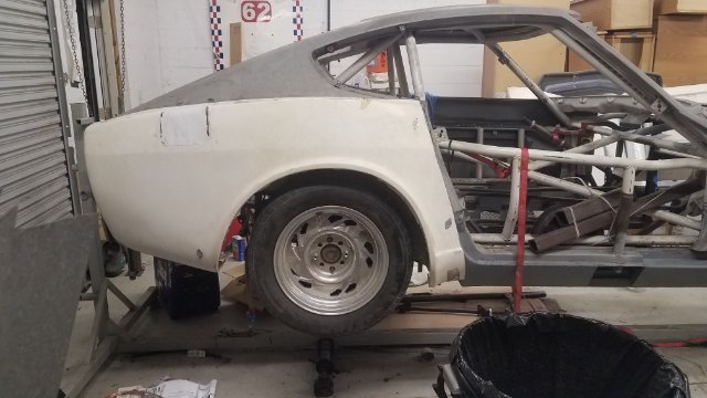
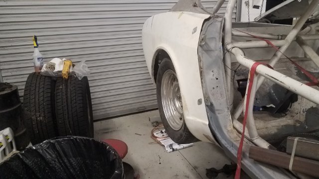
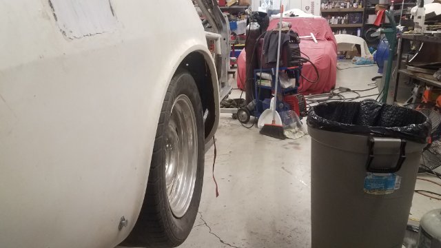
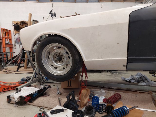
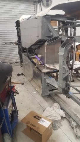
Here are some photos of the body panels as I did a wheel check. These are 15x8 wheels with a 235-50-15 tire. I am planning on running 15x10 so it will be close. I really like this body kit, it is basically stock fenders extended out 2". It came with a cowl induction hood, G-nose, and a whale tail. I will run the G-nose with a custom air dam. I will probably sell the cowl hood. And I may consider the whale tail later.
-
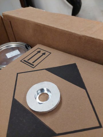
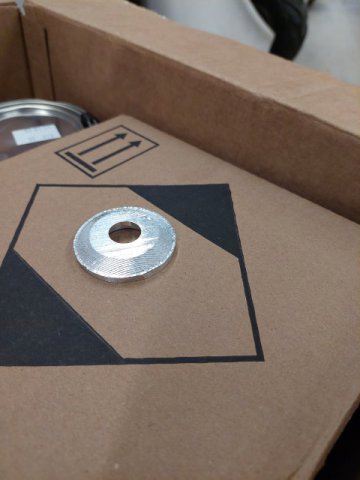
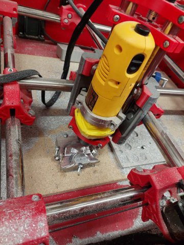
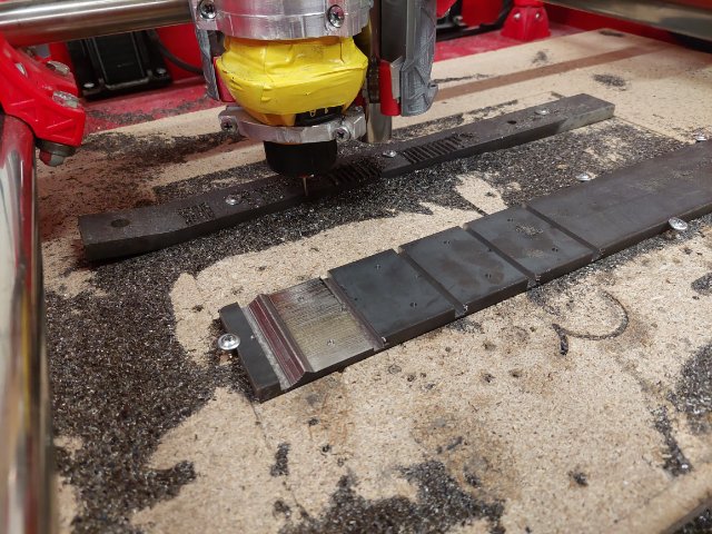
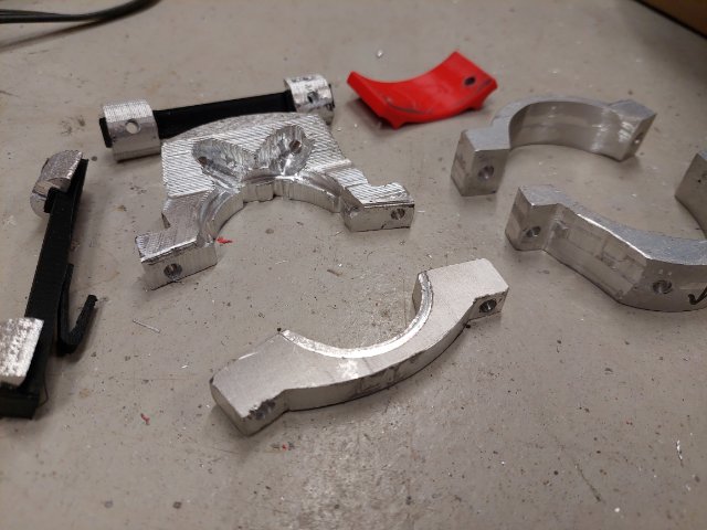
I just ran some aluminum buttons that sit on top of my spring perch top hats. Holes and diameters seem about 0.010" off. But again I suspect the precision is fairly good and more a problem of accuracy. I think with the little practice I could dial this in if I need to. In the next few weeks I want to run some positional location tests to see how accurate I can center punch holes.
-
Twin cam head for the L6 from Derek at Datsunworks
clarkspeed replied to Derek's topic in Nissan L6 Forum
Accolades and recognition will never be overstated for a project of this magnitude performed by 1 person. -
IMSA GTU vintage racer build
clarkspeed replied to clarkspeed's topic in S30 Series - 240z, 260z, 280z
Thanks guys! That is the kind of cool ideas I need for this thing. Only problem is I inherited a heavy 1/8 thk x 2.5 angle iron fuel cell frame in the deck. I hate looking at it. I will need to rethink this, but that is what I had in mind was a flat "protection" panel starting at the aft suspension mounts and terminating at the rear valence and somehow still capturing the envelope of the cell. I think if I keep things flat with no vanes I might be able to get away with it. That tilted cell would definitely make fuel pickup much easier! -
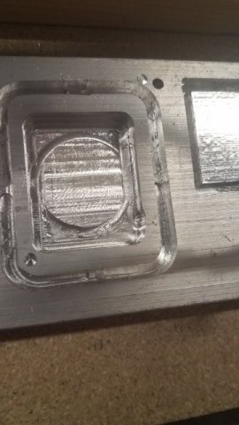
The only tolerances I have checked were just spot checks to see if I was in the ball park. Seemed to be well within .010". I have not run anything that demands better than that but a lot depends on the style of cuts you do. I am most off in the Z axis, but that is due to my inconsistent way of setting 0. Eventually I will add stops to the machine to eliminate that problem. If you build the machine correctly, success with metals is quite easy. But after running it into the ground for a couple months, I have found consistency to be the main issue. Anything that can loosen up will loosen up and it is not always easy to identify the problem. But by modifying a few parts, lock-tite, and a maintenance schedule for tightening, I am getting much more consistent results. When I am happy with that I will concentrate more on accuracy and precision. Although a few people have done it, I would not use this for continuous production work in metal. But it seems OK for some nice 1-off parts. I think a few guys have used their large format machine for cutting sheet metal shapes out of 4x8's which I found interesting. Derek, I had to Google GP03. If you are referring to the walls that is just plywood. If you are referring to the machine parts, it is just a good quality 3d PLA filament. I think it is one of the most rigid materials you can print with. You just can't leave your machine out in the Florida sun.
-
IMSA GTU vintage racer build
clarkspeed replied to clarkspeed's topic in S30 Series - 240z, 260z, 280z
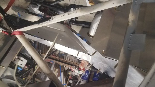
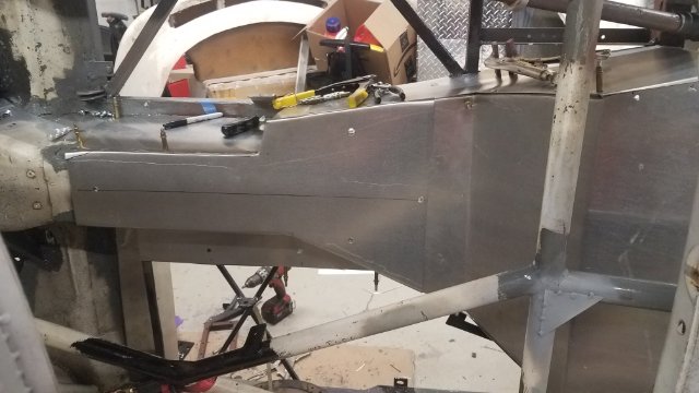
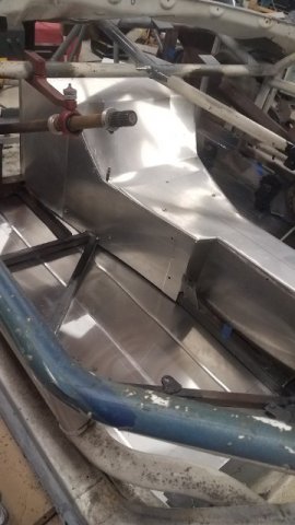
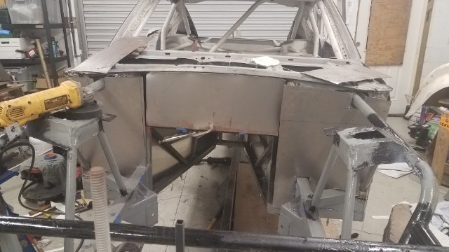
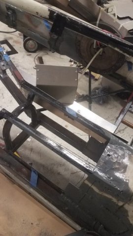
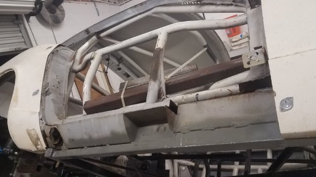
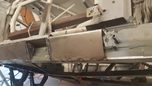
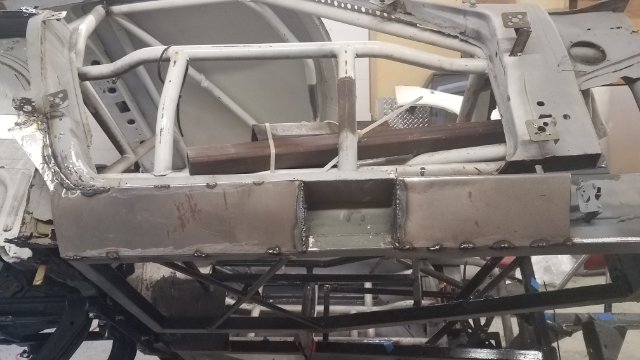
Here are some photos of panel cutting and fitting. Once I was satisfied with the layout of all the interior bits I started planning out the panels. I used 18ga aluminum for interior panels and 18ga steel for the fire wall. I started at the front and went panel by panel working my way toward the back like a puzzle. I took my time and tried to bend or bead panels that seemed too floppy. It came out ok. I am actually thinking I need to clean up the original chassis some so it looks as good as the sheet metal section. I put everything in with clecos and drill all the holes for rivets. All the removable panels have 1/4 turn fasteners. I was a little concerned about getting a good seal from the engine bay, but it seems ok. I was not sure about either welding or riveting the fire wall but ended up drilling for rivets in case I need to rip it out later. I will probably seal all the riveted panels with RTV or similar. Once everything was fitted I pulled it all out and put on a shelf. I think I will install the firewall before I paint the chassis, but paint all the interior panels separate. I have been thinking a lot lately about colors since I am getting ready for paint. I think I will go with a light metallic grey for the interior and gloss black for all the suspension parts.
-
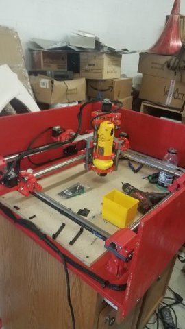
I have been geeking out on this thing for about 3 months now and posting on other forums and FB. I even have a magazine interested in seeing my setup. A 3D printing colleague told me about this possibility about 1.5 years ago and it sounded like total BS. So I started digging around the internet and found the V1 Engineering website and their MPCNC (mostly printed CNC). It has a very good support forum and some amazing project results for a small investment. So I took the plunge just to see what it could do. I slowly acquired all the parts over a 3-4 month period. When I finally had a break on my 3d printer I ran all the parts needed. I assembled this thing in a couple hours, ran a test print with a Sharpie pen, then ran some pockets in wood. I immediately put an aluminum plate on the bed and it went right through it. My eyes were, and still are as big as saucers everytime I use this thing. I have now progressed to mild steel and seem to be advancing the machine capability for the rest of the user base. Just like the 3d printer, I have suddenly found 50 projects I want to do, and so far, just ripping through them. Truth be told, it is not a simple process to produce parts and it is not super fast, but if you have either machining, programming, design, or 3d printing experience, you are already ahead. And if just cutting flat plate, even better. And the satisfaction of seeing a machine you built making chips is better than sex. Well not really, I exaggerate, but I think it is still super cool.
-
IMSA GTU vintage racer build
clarkspeed replied to clarkspeed's topic in S30 Series - 240z, 260z, 280z
I was thinking the same direction. I am building mine loosely to GT rules which allows for a flat bottom. So I was thinking about putting a close out panel there. But I'm not sure how I could work that around the fuel cell. I can't really work on that area now until I get it off the rotisserie. -
IMSA GTU vintage racer build
clarkspeed replied to clarkspeed's topic in S30 Series - 240z, 260z, 280z
I REALLY like your reinforcement of those panels. That rear skirt is so easy to damage. Mine is so wrinkled I may just cut it off and replace like the rockers with little heavier metal. As far as diffusers, they are pretty much illegal for many of us. I'm pretty sure EP does not allow either. But I would say that looks like a good way to attach one! -
IMSA GTU vintage racer build
clarkspeed replied to clarkspeed's topic in S30 Series - 240z, 260z, 280z
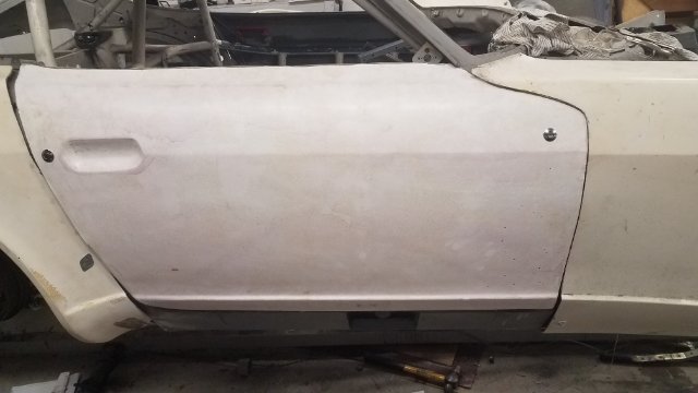
You are correct Jon. I assume vacuum bagging is the difference to make really light weight parts. As you can see, the door has a lot of resin in it and that equals thickness and weight. It's got to be 2 or 3 lbs heavier than it should be. And of course I laid in 1 or 2 more layers than I needed to.. I was just happy to get a ready to paint door out of the process. I am going to experiment with more cloth than matt with the air dam since I don't have any sharp edges to deal with. I think I can get to more like a normal FG part say from the 80's. As I mentioned in another post, I have a Z Trix hood and that thing mind boggling. I can't imagine it being more than 1lb heavier than carbon fiber. But the other thing I learned in this process is I don't like it! It is quite tedious mixing resin, applying layer, repeat, repeat, repeat. The bigger the part, the more you repeat. You can only get so much down in 20 minutes. I mix a quart of resin each round. So my conclusion is small parts and repairs are fine, body panels are a total pain in the ass. Much cheaper and easier to purchase, if you can. -
IMSA GTU vintage racer build
clarkspeed replied to clarkspeed's topic in S30 Series - 240z, 260z, 280z
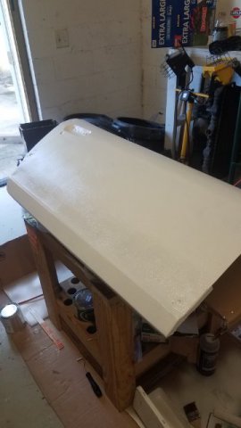
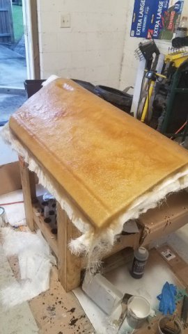
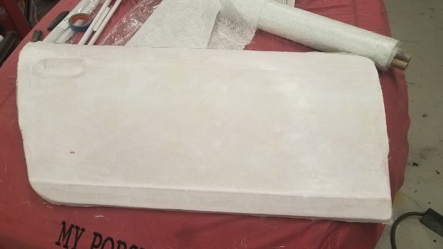
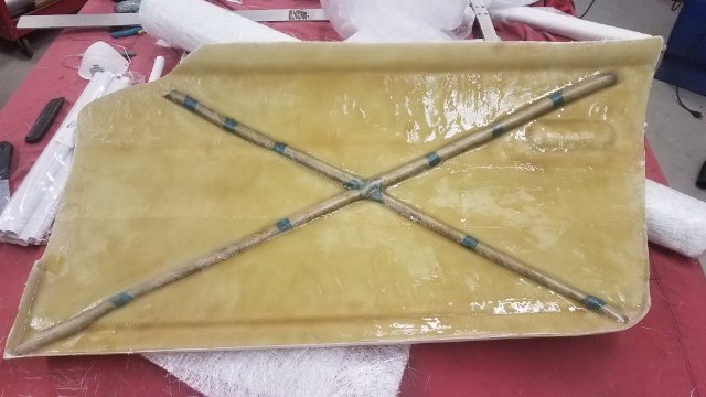
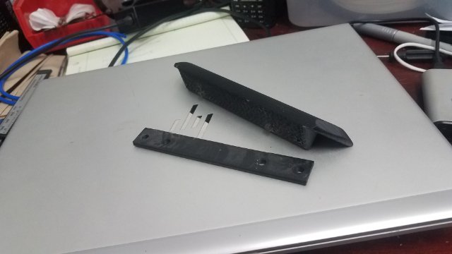
For this build I decided to jump in with both feet and learn how to build fiberglass. I found out early on that I would need to build up a custom air dam so I decided to build out a door as a trial to learn the process. I have done plenty of small FG projects but never something large that involves building a mold tool. You can see the process in the pictures. First sanding and waxing the door (plug) and applying mold release. Then a layer of gelcoat and then laying down multiple layers of heavy matt until the mold has enough strength and rigidity not to break when pulling the final part. The only mistake I made was not smoothing out the original door. I thought it looked fairly straight but it turned out to have some waves in it. It also had some small flaws I thought would be easy to correct in the mold. I was dead wrong. It would have been much easier to correct the flaws on the original door than to work on the mold. You can see the final surface on the mold. Then I prepped the mold, laid in some layers and a new door popped out. It's hard to tell in the pictures but the surface finish turned out great. I added some cardboard rolls in the back to make it stiff. It is attached to the car with push button locks and pins on the bottom. For the final touch I 3d printed a door handle.
-
IMSA GTU vintage racer build
clarkspeed replied to clarkspeed's topic in S30 Series - 240z, 260z, 280z
I think I used 18, it it pretty stout with the bend in it. It would take quite a hand punch to bend it. -
IMSA GTU vintage racer build
clarkspeed replied to clarkspeed's topic in S30 Series - 240z, 260z, 280z
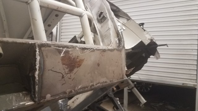
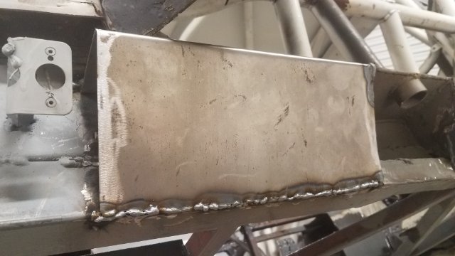
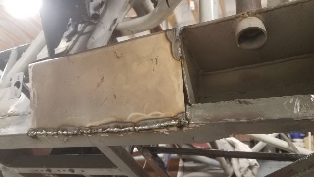
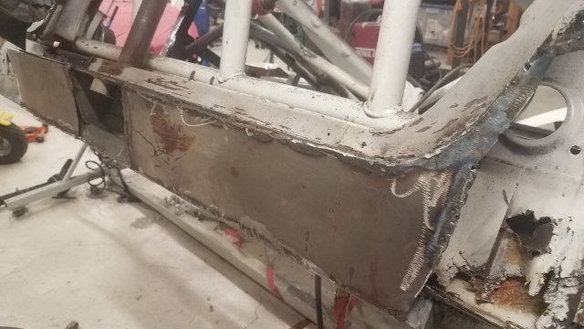
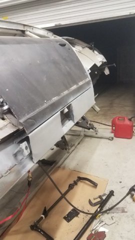
And some really bad weld porn in this post. These were the rocker panels I had to build from scratch. I think I mentioned earlier, for body work I shoot to get close and make it up with very thin bondo to fill in any voids. No hammering of welds, just hours of grinding. I also threw in a rare rocker panel selfie with uncontrolled Covid hair growth.
-
240z SCCA vintage race car, restoration
clarkspeed replied to AydinZ71's topic in S30 Series - 240z, 260z, 280z
A lot of the vintage guys run the V07. Some some openly, some secretly. Most vintage organizations don't measure displacement. I actually had 1 I swapped in and out but destroyed it a few years ago. I am no expert, but based on what I have seen, if you put that crank in turbo, don't try to max out the bore to 0.120. I saw a guy go through 4 blocks trying to get that combo to work. Kept blowing holes through the cylinder walls. Many of these old blocks don't have that much meat left in them. -
240z SCCA vintage race car, restoration
clarkspeed replied to AydinZ71's topic in S30 Series - 240z, 260z, 280z
I can comment on #6 also. The z-trix hood is extremely high quality and amazing light weight. I have one for the car I am building. There used to be a guy in Greensboro, NC under the old Japco Raceglass moniker that made hoods and hatches so thin, you had to add your own supports. I still have one of his hatches. I googled him but couldn't find anything. He was at a Volvo repair shop and made FG parts for many SCCA prepared cars. He must have had a ton of molds. I could say do your own, I have been tuning my FG skills for about a year now. I just did a door and I am confident I could do a hood. But man it is the most boring, repetitive, exhausting, messy, never ending thing I have done with a car. I didn't think I could hate anything more than body work, but this went way past it. And the results are nowhere close the the Z trix stuff. My surface finish was great,, but the WEIGHT was not.. The Z Trix stuff is rigid and still paper thin.. I assume he vacuum bags the stuff.. I still have an air dam to finish, because none exist for what I need. -
240z SCCA vintage race car, restoration
clarkspeed replied to AydinZ71's topic in S30 Series - 240z, 260z, 280z
I can comment on #5 and #6. I have run the Mischimoto with good results. I also ran cheap Griffin I think from some Ford app. I literally had to block parts of it on cool days to keep water temp above 160. My personal opinion, and there are a lot of opinions out there, dry sump is best. If not dry sump, then a good racing oil pan with trap doors , windage tray, AND an accusump is next best. And third is a stock oil pan with accusump. The car I have now has the latter but most cars I build are option 1 or 2. -
240z SCCA vintage race car, restoration
clarkspeed replied to AydinZ71's topic in S30 Series - 240z, 260z, 280z
Wow Cary, I didn't know you went that deep into data acquisition! Problem is when I start talking about this stuff,, people's eyes glaze over. I have my software split into 2 modules depending on which analysis I am doing. 1 is for driver performance with related KPI's. it looks at max use of G circle, racing lines, lap comparisons, throttle and brake use etc. It is combined with video feed. The other is car performance stuff like downforce, gearing, under/oversteer etc.. Both have lots of custom graphs and math channels that show problem areas as red. The KPI's provide important historical reference. I haven't tracked engine parameters much because I am out of channels, but intend in the future. I really like your idea of a simple 1 or 0 flag to scan. I may even be able to get that displayed before I get out of the car! Don't know I you saw my last post in the sim racing thread. I spent some covid time fabbing a cockpit display for time slip and slip rate. I have become dependent on this from sim racing. I think that will improve my lap times immensely. -
This is going off topic, but here is a video I made last year of the screen I developed for my race car. The Race Technology stuff is all programmable which doesn't make it easy, but on the other hand you can develop a screen that shows anything you want. I used a video screen instead of their dash but may switch to a dash in the future. it is a little jerky this way. Ignore the track map on the left, it only shows up on later playback. The screen on the right is mounted in my peripherical view. The top lap time is best overall, the bottom is predicted. The top bar chart is % rate of time change, think instant feedback that you are gaining or losing time at that point on track. Brake harder, it goes green, miss an apex, it goes red, etc. The bottom graph is total lap delta to the best lap. and there is a counter above it showing how many seconds ahead/behind you are. Race Tech Display.mp4
-
As I was just posting on Aydins build thread and forgot to mention earlier in some threads, I have grown quite reliant on live time slip data when I practice and qualify in iracing. Jon does Asseta Corsa provide this? I just assumed it did. With time slip rate you can see immediately if you blew the turn or found a faster way. That's why I don't really want to pursue a driving coach, if I ever get to the point where I can't find more speed experimenting, then I will have plateau at a very high level. But of course consistency wins races, not ultimate lap times. And consistency comes with being very comfortable and confident at executing. But I think we were talking about data in one of your threads. The ability to see that time slip real time is much more important for the non-pro level driver. Instant feedback is a wonderful thing. Could even benefit at an Autocross. And you don't need to analyze data. Just the feedback in your peripheral vision or in your ear. There are a few systems out there that provide this. I upgraded my Race Technology stuff to do this in my car. There is a verbal unit out there that does this but I forgot the name. This is exactly how the pros operate. They experiment ALL the time and have the ability to analyze good/better/best with their head.
-
240z SCCA vintage race car, restoration
clarkspeed replied to AydinZ71's topic in S30 Series - 240z, 260z, 280z
I don't normally run a volt gauge, alt failures have been very rate for me. Oil temp is good, best to mount sensor in the pan. You can always add a Traqmate later if you want to analyze your driving and skip the dash. They go for around 400 used. They are fine for most basic analysis, like looking at speed vs. Distance graphs and g-force circles. Most people stop there. I need much more than that to analyze tire compounds, best gear ratios, understeer, etc. Etc. If you really just want to improve driving, a system that gives real time time slip data back to the driver is a must. Just forget about analyzing data.. Since I have been sim racing, I rely on it extensively. Just something that shows you real time how your rate of time slip compares to your best lap and actual lap or segment delta to best lap. Everytime you try something different in the car, you get immediate feedback if it worked. Some systems have easy to read bar charts and even a voice response in your ear. -
240z SCCA vintage race car, restoration
clarkspeed replied to AydinZ71's topic in S30 Series - 240z, 260z, 280z
I think Cary is referencing just 3/4 tubing with external bearings. Maybe even a rod end near the steering wheel. I struggled with this decision on the car I am building. In the end I went with the Sweet collapsible column for safety reasons but it is not so light. I am not sure what the rule book says for EP. Yea you can get into a lot of complexity on data/dash systems. If you decide to take the plunge maybe we talk on the phone. Yea dash + data is not so cheap. But it opens up a lot of potential. But the potential means nothing unless you can apply it. I think the cheapest solution is the Race Technology Dash 2. It will log 8 channels and the analysis software is pro level. If you just log oil pressure, oil temp, and water temp you have something to look at along with all the GPS and G force data. I had Greg put 1 in his LeMons race car for those reasons. You can easy add throttle position and the O2 sensors if you want and that is a pretty solid setup. Greg runs Traqmate in his EP car which drives me nuts. The software sucks. I have to put much of the data in Excel to analyze. But again, complex questions demand complex answers. If you go for something we can talk. I know a little about a lot of things, but data acquisition is something I know a little more about. -
240z SCCA vintage race car, restoration
clarkspeed replied to AydinZ71's topic in S30 Series - 240z, 260z, 280z
Now you are getting into some fun stuff! Greg runs races less than 1 hr so something to consider unless you have some big electrical demand. I am going to run a Geo Metro alt on my next engine as a small alternative, but I have not got to the engineering for that yet. AIM has a good product. Think about where you want to be in future state before purchase. I know quite a bit about data acquisition and I am officially Greg's race engineer BTW. Main questions are do you just just want a dash and how much data you you want to analyze? Are you just looking at driver performance or logging of multiple car parameters? Are you planning carbs or EFI system? They are both legal for EP. -
It works very well.
-
240z SCCA vintage race car, restoration
clarkspeed replied to AydinZ71's topic in S30 Series - 240z, 260z, 280z
Sorry I mis-posted -
240z SCCA vintage race car, restoration
clarkspeed replied to AydinZ71's topic in S30 Series - 240z, 260z, 280z
Looking good. Man that is a lot of welding. I don't see any holes in the firewall for the brake clutch MC's?