NewZed
-
Posts
6700 -
Joined
-
Last visited
-
Days Won
72
Content Type
Profiles
Forums
Blogs
Events
Gallery
Downloads
Store
Everything posted by NewZed
-
Fuel pressure drops to zero as soon as motor is shut off.
NewZed replied to Kamaka Z's topic in Fuel Delivery
Never mind, mistake. Erased previous comment. Might just be poor quality on the aftermarket FPR. It might still wear in though, with time. Probably best though, If you confirm that it's the 280ZX FPR, to take it back and exchange it. They're not supposed to leak down. -
Fuel pressure drops to zero as soon as motor is shut off.
NewZed replied to Kamaka Z's topic in Fuel Delivery
You could block the return line and test that way, or block a port on the 76 FPR and put it back on. Or you could just use it for a while and see if the new FPR settles in. Might have some surface rust inside, if "new" means "new old stock". I'd drive it for a while and see what happens. Won't hurt anything. Might be aggravating. If it's leaking at an injector you'll probably notice it's very rich on starting. Might even foul a plug. -
Fuel pressure drops to zero as soon as motor is shut off.
NewZed replied to Kamaka Z's topic in Fuel Delivery
Not normal for a factory FPR. Did you switch FPR's or use the same one? It would only take a small piece of rubber or teflon tape to hold the seat open in the FPR. Some old FPR's will occasionally lose pressure but hold most of the time or vice-versa. It looks like maybe you only checked once before and once after. You don't give much detail. Regardless, it will only affect starting the engine quickly. -
Did you try rotating the wheels back to where they started? Did you rotate the wheels or did a shop? Going back to square one would tell if it's the wheels or the front end parts, or if something got damaged. Another thing people do is to put on a different set of wheels. If you have them available. A couple of spare tires on the front end might be informative. Might be too late, since you've already torn things apart, but if you end up in the same dilemma in the future, worth a thought.
-
Help locating TDC on head, mid head gasket job
NewZed replied to DeLorean's topic in Nissan L6 Forum
He's probably past this already and trying to figure out how to get the gear back on, because the chain seems too tight. -
Help locating TDC on head, mid head gasket job
NewZed replied to DeLorean's topic in Nissan L6 Forum
Grab the gear and stick it on, with the camshaft dowel in the gear hole. Turn the gear and the shaft until the notch and groove line up. Remove the gear. Install the head. Don't make it complicated. The riskiest part is letting the head slip off of whatever you're working on and landing on a valve head. Let your eyes tell you if it's right. If there's a valve sticking out and about to go in to a hole with the piston at the top, that's wrong. If you need leverage on the head because it's free, take a piece of steel or wood and drill a hole or two in it. Bolt it to the bottom of the head as a handle. If you can't move the gear, put the bolt in and use a wrench on the bolt. But you'll have to shock the bolt head loose to remove since it will have tightened and will want to turn the shaft when you try to get it back out. A dead blow hammer, hammer, sledge, piece of 2x4, tapped on the wrench handle should do it. Go slow and look at how the parts fit together. -
Help locating TDC on head, mid head gasket job
NewZed replied to DeLorean's topic in Nissan L6 Forum
There's a notch and a groove. Picture in the manual. The factory one. EM. -
Help locating TDC on head, mid head gasket job
NewZed replied to DeLorean's topic in Nissan L6 Forum
How to tell that it's at TDC or how to turn the camshaft? You can use a wrench on the flat sections of the cam shaft, or some pliers. You can just hold the sprocket up to where it would go and check orientation of the sprocket notch. You can also measure how far the valves stick from the bottom of the head and compare to the holes they go in. -
I have a question about the cam I put in my 350
NewZed replied to Tatterone's topic in Gen I & II Chevy V8 Tech Board
The answer to your question about duration is on page 8. Degreeing the cam would at least tell you if it's installed correctly. You still haven't answered the questions about the rest of the engine. Compression ratio, engine management, timing (maybe you just need to set the ignition timing correctly), etc. The very basic stuff. No point in swapping cams without addressing the basics. That's all I have. Good luck. -
I have a question about the cam I put in my 350
NewZed replied to Tatterone's topic in Gen I & II Chevy V8 Tech Board
https://www.lunatipower.com/PDF/Lunati-Catalog.pdf -
Spend some time on this site - http://www.diyautotune.com/
-
They're just wires. You don't need to do anything, just do what you want.
-
240Z to Z31T CV Adapter Plate OPTIONS!!!!!!!!!!!
NewZed replied to DatDude's topic in Fabrication / Welding
cygnusx1 did a ton of legwork and shared it. If cygnusx1's diagram isn't close enough, then nobody's will be (did you even look at it?). And you don't need to stay outside, bring the 300ZX shaft in to your nice warm home. The dimensions you need are on the CV shaft. Or take the shaft and the drawing to whoever is doing this work so cheaply for you. Your best band-aid for getting back on the road might be to use the u-joint half-shafts, with R200 open-diff axle shafts. Clip-in, bolt-in, and cheap. -
This guy says RB crank bolts are a problem. http://www.lewisengines.com.au/rb-tech/
-
240Z to Z31T CV Adapter Plate OPTIONS!!!!!!!!!!!
NewZed replied to DatDude's topic in Fabrication / Welding
Here's another thought, since you're welding - buy some junkyard 300ZXT companion flanges and cut the flange off. Fit them to your Z car companion flanges. Weld. -
240Z to Z31T CV Adapter Plate OPTIONS!!!!!!!!!!!
NewZed replied to DatDude's topic in Fabrication / Welding
These guys would probably make you one if they don't already. Four 300ZXT-spaced holes, instead of six 108mm CV holes. Still spendy. http://www.driveshaftshop.com/import-axles/nissan/nissan-datsun-510-240z-4-bolt-axle-flange-to-108mm-cv-conversion-plate-rear-axle -
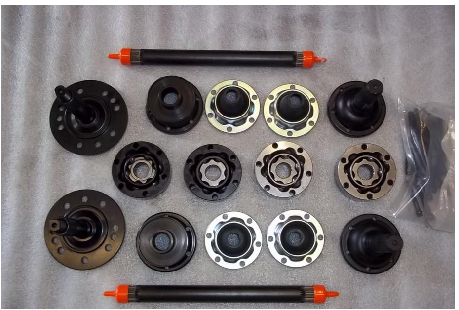
Here's some good stuff on cage materials. Apparently there's some compromising involved depending on application. I wonder if a new cage would get you back to where you started, or if the races and balls have too much play due to wear. #4. http://driveshaftshop.com/blog/?p=567 The fact that the cages are worn on both sides makes you wonder also though, if there was enough travel available in the first place. Just wondering, don't know much.
-
240Z to Z31T CV Adapter Plate OPTIONS!!!!!!!!!!!
NewZed replied to DatDude's topic in Fabrication / Welding
There's not a whole lot to the specs. besides a few measurements. It takes some work to get them right but the whole set of numbers is not complicated. A center, some holes, a parallel plate. You could take the 280ZXT CV drawing and change the six holes to four. cygnusx1 has done 90% of the work for you. Take the 4 hole measurements yourself. Make it thinner if you're welding and doing the other side too. The companion flange dimensions are the same for the 27 and 25 spline hub axles. http://forums.hybridz.org/files/file/3-cv-adapter-print/ -
Could it be that the shaft was either too long or too short? Looks like the balls were getting forced to one side of the cage. How does the other cage look? And the balls.
-
'79 was running, now no crank, no start
NewZed replied to Connor280ZX's topic in S130 Series - 280ZX
Put the gears in neutral, turn the key On, and short the small spade on the starter solenoid to the big cable from the battery, at the starter, using a wrench or screwdriver. That will power the starter with about the most energy available possible. If it starts, you'll know it's not the starter or battery or cables. And you'll have a fail-safe method while you try to figure it out. Make sure it's in neutral since you'll be bypassing any safety mechanisms. There will be some sparks, just hold it there while the engine spins. You can also use a length of wire from the solenoid spade to the battery + terminal. If you want to go one step further, measure voltage at the coil when you turn the key On to make sure it has the potential to start. -
*240z Front Brake Rotor Differances from 260 and 280*
NewZed replied to DatsunZman04's topic in S30 Series - 240z, 260z, 280z
Dang, I wasted 2 minutes on Google. SleeperZ got here first. -
cable operated heater control valve thermostat attached?
NewZed replied to ORANGEV8Z's topic in Miscellaneous Tech
If it's like the 280Z's then it controls coolant flow based on heater core temperature. Like a thermostat, except it only covers a range of temperatures around the manual setpoint. Keeps things from getting too hot when coolant flow is high, and too low when coolant flow is low, like at idle. Can't find it described in the ZX FSM but I think I've seen in the Z FSM's. They're liquid-filled tubes and usually blown out by now. If you find yourself turning the heat down as you get on the highway at higher RPM it's probably not working. You'll have to take more parts off to find where it's clipped on to the heater core. Here's a source for valves (aka watercocks). http://www.datsunstore.com/heater-control-valve-7983-with-manual-heat-rebuilt-p-276.html -
I'll stop after this one. The better CV shaft topic is just too interesting to leave. I don't see a lot of "plunge" room on Joe's axle shafts. Kind of suggests that he's going with the non-floating design. So, "trust but verify" would be the way to go.

-
I wonder who is making the "kit". He says "the manufacture®" on the page. [Odd, "r" in parens = ®.] He seems good at collecting the right parts though. The factory type CV shafts will probably disappear eventually as the reman market runs out of used shafts. This kit is rated at 800HP by the manufacture.
-
As I understand the 930 design, they can change length by both means. The CV joint has a range, and the axle splines have a range. Some people lock the joint on the spline and just use the CV range. Or let the joint float for more range. But if the joint floats on the splines then the splined surfaces become loaded sliding surfaces with all of those inherent problems. You'd need to know how Joe built his axles to know what to worry about. And comparing the range of lengths is apples-to-apples. Too short is too short, too long is too long. Just sayin'... Speculative answers is why people post questions in the forums. New ideas. The more the better.