NewZed
-
Posts
6700 -
Joined
-
Last visited
-
Days Won
72
Content Type
Profiles
Forums
Blogs
Events
Gallery
Downloads
Store
Everything posted by NewZed
-
Gasket link. The site kept pasting an old file. https://www.rockauto.com/en/catalog/nissan,1978,280z,2.8l+l6,1209260,engine,intake+&+exhaust+manifold+gasket+set,10220
-
RTZ seems to do good work. I'd trust the dimensions that guy above used, which he got from the RTz post that he linked. Or, the gaskets are probably correct. If you have one around.
-
You might want to reserve judgement until after you (try to) install the parts. They've had problems in the not so distant past. July.
-
Can't separate oil pan / bottom block on 1981 280zx
NewZed replied to adsdsasdasdasda's topic in S130 Series - 280ZX
Not clear what this means. There is no "upper pan". This is a 280Z but it's the same engine. You posted Sunday so probably already got it done. Good luck. https://www.carpartsmanual.com/datsun/Z-1969-1978/engine-280z/cylinder-block -
Did you grab the engine and see if it moves? That's all I was suggesting. Trust (your ideas). But verify (that they work). “Give me a lever long enough and a fulcrum on which to place it, and I shall move the world. ” ― Archimedes
-
I'm sure that you've considered it and I don't know what you would do to cure it if it is a problem but those engine mounts are very long lever arms. What happens if you grab the top of the engine and pull it side to side? Probably best to test it now than to wait. Even the mass of the engine in a turn will place a lot of force on them. Just something that grabs the eye from the pictures. Unusual engine mounting. Edit - fore and aft also. Much lifting force on the rear mount under braking. Fatiguing of the front crossmember engine mounting points might be a problem. It wasn't designed for that type of twisting force. And you've moved the elastic portion up to the engine at the top of the lever arm. The attachment to the crossmember is all metal. Hate to be a Debby Downer but you have access now to work on it, rather than later.
-
Did you see the turbo threads here? Kind of hard to find. https://forums.hybridz.org/forum/90-l-series/
-
77 280z Injectors not getting power
NewZed replied to Acesss's topic in Trouble Shooting / General Engine
The computer grounds the injectors every third spark. It uses the wire to pin 1 to monitor the ignition system. There's a pretty simple electrical system check in the 1980 EFI book. Check the circuits before getting crazy with parts. That's why they wrote the books. https://www.classiczcars.com/files/file/32-efi-book-1980/ -
It's not uncommon. I added a terminal post near the battery for a few things. If I had a bunch I'd probably just install an auxiliary fuse box. Otherwise you have a bunch of inline fuses to take care of. There are many out there but a trip to the salvage yard would probably find one that is weatherproof and high quality. Depends on where you want it mounted. Looks like I'm on the same page as jhm, who replied as I was writing.
-
ideas on how to get this rusty bolt out
NewZed replied to adsdsasdasdasda's topic in S130 Series - 280ZX
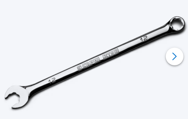
Seems like you might need a better wrench. A six point box end would be best. 12 mm I believe. p.s. forgot to mention the original impact wrench. Tighten up the wrench on the nut. Then hit it with a hammer. p.s. 2 - it will take a lot of heat to get the flange hot enough to hurt the seal. A torch on the nut should help. Doesn't have to be red hot. https://www.lowes.com/pd/Capri-Tools-12mm-WaveDrive-Pro-Combination-Wrench-for-Regular-and-Rounded-Bolts/5001577325
-
2jz gte ecu?? Continuity across crank and ground?
NewZed replied to sharkys280's topic in Toyota L6 Forum
Barely know what you're working with but I did find a crankshaft position sensor online for the 2jz and see that it's a two wire unit. That means it's a variable reluctor system. There will be continuity across those two pins in the sensor harness to the sensor. There should be a resistance of a few hundred ohms, typically. It's not clear what you mean when you say you measured with the plug connected and got continuity. Can't tell which side of the plug you're measuring, to the sensor or to the ECU. Anyway, the signal to the ECU is generated when the metal teeth of the trigger wheel pass by the sensor. The sensor has to be within a certain distance from the sensor, that's very important. There's spec but it's usually a few thousandths. Pretty close. The basic testing is to measure resistance across the two pins to be sure the coil is intact and will work. Then set the air gap. Then test that a signal is being generated. https://www.jdmgarageuk.com/90919-05037.html Here's a pretty good video about the basics. . -
Probably just fine. The polyurethane products were developed as a performance improvement. More precise steering, less wheel movement. The aftermarket will hype and sell whatever they can.
-
Actually it's rubber in the back, poly in the front. The front bushing takes the force under braking on the Z's, under compression, and is the one that you don't want compressing too much, making the steering squishy. But the poly should not have split. It does take a lot of side forces as the rod moves up and down with the suspension. But usually it causes the rod end to fatigue and break off. Seems like you got a bad batch of polyurethane. Bad chemistry, or a knockoff.
-
Share.
-
Anyone running a Schneider 270-60F-14? Questions about idle
NewZed replied to juggernautjoee's topic in MegaSquirt
https://www.schneidercams.com/270-60F-14_LET6.aspx Did Schneider give you an idea of what vacuum reading you should be able to get? Opening up the lash effectively "detunes" the cam. Less lift. Seems like an odd suggestion. Does your engine have any EGR remnants? The EGR passages have been known to rot inside the manifold and leak internally. -
Might help your conversation to distinguish between "no signal" and "no signal showing in Tunerstudio". The first is a problem at or with the hall sensor itself, the second could be anywhere in between or at the computer.
-
Sounds like front wheel bearings. Your tires will wear out faster also.
-
I have, in the past, placed the plug wires on my L28 280Z engine in reverse rotation order. #1 was correct but the rest were placed in clockwise rather than counterclockwise order. The engine started and ran but it ran terribly. Since I had only replaced the wires as a tuneup on an engine that ran well I knew immediately that I had screwed up the firing order somehow. It must have been running on only two cylinders. 1 5 3 6 2 4 1 4 2 6 3 5 In short, maybe doublecheck your plug wire placement. Good luck.
-
Help me evaluate this car for sale
NewZed replied to z_noob's topic in S30 Series - 240z, 260z, 280z
Bring a Trailer is a good place to look. Search for "240Z" and you'll be able to get notified when a new one shows up. https://bringatrailer.com/datsun/240z/ -
Help me evaluate this car for sale
NewZed replied to z_noob's topic in S30 Series - 240z, 260z, 280z
I guess my basic point was that when signed in you "feel" like you're part of a large community. But, actually you're only part of the signed up and signed in community. On top of that, even the Facebook group you linked to is a Private Group". So I assume that after logging in I would have to be accepted in to the Private Group in order to see the classifieds. Why would anyone sell a 240Z in the Private group when they can put it on Marketplace and get a bigger audience? It's not a criticism, it's just an observation. The internet has changed from the original purpose of sharing information to one of capturing attention. Used to be you could see everything and you only had to "join" if you had something to say.
-
Help me evaluate this car for sale
NewZed replied to z_noob's topic in S30 Series - 240z, 260z, 280z
These Facebook links are kind of funny, relative to the other "are forums dying" thread. If a person does not have an account and sign in they can barely see anything. It's worse on Marketplace, you can look at about ten items before Facebook blocks you unless you sign in. So it's kind of a members-only craigslist.
-
Help me evaluate this car for sale
NewZed replied to z_noob's topic in S30 Series - 240z, 260z, 280z
Also don't see engine management shown. That can get expensive. The video is worth watching for anyone else interested. The guy should just finish it. The door gap is off. Might have been in a past accident. Could be a fun project for the right price. -
Help me evaluate this car for sale
NewZed replied to z_noob's topic in S30 Series - 240z, 260z, 280z
Apparently it is not in running condition. So, basically, it is a collection of parts. Looks like he wants about 75% of what he paid for the parts. That seems steep. $28,500/38,290 If you wanted that exact set of parts then you might consider it as a 25% off sale. But since the car is not running you can't tell if the set of parts will actually make a nice car. Not even clear that the engine runs, and it doesn't say anything about engine condition. Besides that you'll need to pay for a paint job for the hood if you want it to look decent, unless you ho with the classic primer black. Also, I don't see the shiny rims on the spreadsheet. They might not be included. Looks like a risky endeavor unless you plan to sell the parts separately for full price. Good luck. -
Ask one of the AI's and see what it says.
-
Here's some visual food for thought. Looks like lots of space. Maybe no problem? Found the picture on eBay. I'd share the link but they put way too much stuff in it. There's an extra T. Don't know if it matters.