Zmanco
-
Posts
1568 -
Joined
-
Last visited
-
Days Won
1
Content Type
Profiles
Forums
Blogs
Events
Gallery
Downloads
Store
Everything posted by Zmanco
-

Bolt in Rear Drum to Disc Conversion
Zmanco replied to hawaiiz's topic in Brakes, Wheels, Suspension and Chassis
Why not swap the calipers from side to side? That way you could bleed without removing them. I'm pretty sure others have done it without clearance issues. -
As a general statement I agree. But if you have good experience soldering and have an EE-type background, then you probably can get by without it - I did, but you're trading time for saving ~$50.
-
Your entire engine bay is really looking fabulous. Very nice install of the FI/MS! If you don't mind a mild thread hijack, I keep noticing your seats - they look like they're very similar to the stock seats, but covered in leather? Did you just recover the originals, or are they from some other vehicle? [/highjack]
-
I can't help you with your question about the CA smog stations. As for fixing an MS board, there are people to whom you can send it and they will diagnose and fix it for a fee. If you're not already familiar with building electronic circuit boards, you might be better off buying one already assembled. As for tuning, I'm just getting started with it. In theory, you are correct, you just enter values in the boxes. In practice, knowing what values to start with for your particular engine, and how to adjust them to improve things, is the issue. I'm actually enjoying the learning process, but it takes quite a bit of time. Going into this project I expected that I would be able to start with the settings (msq file) from someone with a similar setup and then just fine tune from there. In reality, that hasn't been successful. I've had to find a little here, and a little there from different people to amass most of what I need. If you know someone already experienced with megasquirt, that would make things go a lot faster I think. I'm not trying to discourage you from this, but suggest that you be fully aware of what's involved if you go this route. I will say that so far, I have no regrets at all for having gone down this path.
-
After further email with Matt, turns out it's not possible to use the Hall input off the negative coil with an MSD. I guess I should have realized because: a) the coil is floating (electrically) with the MSD box (neither side is referenced to ground) with its multiple sparks at lower rpms it wouldn't have worked anyway. I changed the board for a points trigger and connected to the MSD's tach output and she runs! Now I need to tune. Wow, glad that part is behind me PS. Nowhere in the MS documentation is this covered. Is there some place on this site where we can list this sort of thing? I'd hate for someone else to have to go through this.
-
I think you are correct, I think there is a problem with tach input circuit. That is the only thing so far that explains everything. I've confirmed I have continuity from the negative side of the coil to the tachselect jumper on the main board, so I'm pretty sure my wiring is ok. Power to the MS is solid - I used Megatune to monitor the battery voltage during cranking and it stays above 10v. I've got the board out of the car and have gone over the assy instructions and can't find any mistakes yet. I followed instructions 50b and 52 for the Hall sensor. For those of you still with me, does that seem right for triggering off the coil?
-
Update: I went back out in the garage, and with the dimmer light, I can see the injector LED flash twice when I turn the ignition on, just as it should. I heard the injectors firing twice too. I also found out that if turn the ignition on, wait for it prime the injectors and let them fire, then turn it off, and then repeat a few times, that when I try to crank, it almost starts. I don't think I have any hardware issues - I think I must have some setting incorrect. I'm attaching the msq file. Anyone with MS experince mind taking a look through it and see what might be causing me to not have enough fuel be injected? I feel like I am so close!!! megasquirt200705281127.zip
-
I don't have a stim board and was hoping to not need to buy one. Just hate to buy it and use it once. But that may my next step. How would you check the tach signal? I am running off the negative side of the coil. I did temporarily route some shielded line to see if there was maybe interference, but it didn't make any difference.
-
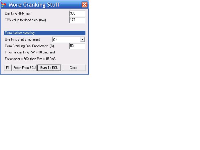
I'm installing MS1 v3.0 with MSnS fuel-only on my N/A L28. I suspect I am not getting any fuel dispensed by the injectors. I've confirmed I have spark and fuel pressure to the rail. If I pull the plugs after cranking, there is absolutely no smell of gasoline. Now and then if the engine has sat for a few minutes, when I first crank it, it acts like it just might start, but that only lasts for about 1 second and then it's back to the usual crank and no start. Another clue: none of the 3 LEDs on the MS box ever light. I've confirmed that the flat side is towards the DB9 connector. I have the 6 injectors split into 2 banks and neither appears to be firing, or at least not enough. I thought maybe there is an issue with the FET on the main board, but it seems unlikely both are bad. I've check my soldering for bridges and cold joints and all looks good there. All the sensors show normal readings in Megatune. I've attached a few screenshots showing the cranking settings. I've experimented with changing the pulse widths on the cranking table, but that doesn't seem to make any difference. I also tried connecting my DVM to one of the injectors wires to see if I could measure any voltage while cranking, but I'm not getting anything. Unfortunately I don't have access to a scope. At this point I'm pretty tired and keep thinking there must be something simple I'm missing. Suggestions?

-
I'm chasing down leaks on my new FI installation. All was well except that 1 injector was leaking where the hose meets the injector body. I pulled everything apart, changed that hose, and now a different injector is leaking at the same place. I used Goodyear FI hose with a bright blue liner. I'd never seen that before but wonder if that may be part of the issue. Also, why not put a clamp on the hose where it attaches to the injector? Everywhere else fuel hose is used it's clamped. BTW, I do have the little piece of metal, kind of like a washer with an edge around it, on all the injectors. I thought that was supposed to help clamp the hose. Thoughts?
-
Hey, great new! I'm not far behind, just need to finish the surge tank install at the back and I'm ready to crank over as well. Last night I verified that the MS reads all the sensors. I'm sure it's a great feeling for you - looking to have the same feeling shortly
-
For a 3 point belt, how is the Scroth better than something like the Wesco?
-
Wiring a 280zx altinator to a 240. (Diode question.)
Zmanco replied to Astral Ace's topic in Ignition and Electrical
You can use just about any diode. Just make sure it's rated for at least 1 amp and 50V. Higher values won't hurt, smaller might not last. On my 73 without the diode, the engine kept running after turning the ignition off. -
L series - Positive crank case pressure, too much.
Zmanco replied to proxlamus©'s topic in Nissan L6 Forum
Ryan, did you take those compression readings with the new cam? I ask because I know that longer duration cams result in a lower "effective" compression ratio allowing you to run a higher CR without detonation. I suspect this may be part of what is going on with your readings. -
Mobeythevan, I appreciate what you said and your desire to put good information out on this forum. I had thought about trying to take this further, but in the end I decided not to because:- There are so many permutations and variables that it would be impractical (and too long to read) to discuss all of them. - Unlike mechanical things (like Jon's great summary of diffy's for S30s) the MegaSquirt world is constantly evolving because of its open nature - especially with regard to the firmware and tuning software. - The MegaSquirt website has a TON of information, including forums, and although they aren't as tightly run as this site, a little searching and browsing yields lot's of good information. I think it's safe to say that converting to MegaSquirt isn't rocket science, but none the less, it does require a lot of research to be done well, just like every other conversion on our Zs.
-
Thanks Xander, good catch. I've gone back and fixed it.
-
If you are looking for replacement seat belts, I am using 3 point belts from Wesco http://www.wescoperformance.com. With these you have new webbing and mechanisms, and the fit into my 73 was quite good actually. They are retractable. They're not a replacement for a proper racing seat/harness, but I'm sure they're safer than what I took out.
-
I'm in the process of installing a MegaSquirt system and found it a bit hard at first to understand the various choices. So below is a brief summary of what I learned and a recommended approach for how to determine the best solution for your application. It is not a tutorial on how to tune with MegaSquirt - there are others with far more experience who are better qualified to write it. It is also not a replacement for the MegaSquirt website http://www.megasquirt.info which is loaded with good information. I would suggest you use this as an overview of the basic selection process and then spend the bulk of your time on the MS website. Keep in mind that MegaSquirt is an “open” project designed to work on any vehicle. The original work was done by 2 guys (Bowling & Grippo) who freely published their designs for the circuit boards as well as their software/firmware. They do not sell anything. To buy a kit, or a finished unit, you need to go to one of several companies that sell them. The MegaSquirt website will take you to their sites. Also, other have taken their code and written their own firmware with new features and enhancements. That’s part of the value of this approach, but it can also make things a bit more confusing. Step 1: Which Main Board? MegaSquirt is available in several main board configurations. As of this writing, there are 2 choices still available: v2.2 and v3.0. In simple terms, the v3.0 board is a redesign of the earlier v2.2 and is more robust and reliable. For you EE types, it is now a 4 layer board with separate power and ground planes. It also has protection built in for the injector drivers. This means it is a more robust board and also more tolerant of electrical noise and wiring mistakes. But there is nothing wrong with the v2.2 board and if properly installed, it will perform well. In general, even though the v3.0 board is a more expensive, if you are starting from scratch I would recommend that you use this board. Step 2: Which Processor? The original MegaSquirt board and firmware (code that runs on the board) were written for a Motorola 68HC908 microprocessor. While not a cutting edge device, it has plenty of capability for most FI applications. The default firmware has an 8x8 table for tuning the fuel injection map (not to be confused with MAP which means Manifold Absolute Pressure). Main boards that use this processor are considered to be "MS1". There is a daughter card (meaning a small circuit board that plugs into the main board) available that has a more powerful Motorola MC9S12C64 microprocessor. It also has some additional circuitry that is useful for controlling ignition events (spark). MegaSquirt applications that use this card are called "MSII". See the MegaSquirt website to learn more about the differences. Note: Either processor can be used with either main board. Hence you can configure as a MS1 v3.0, or perhaps a MSII v2.2. Step 3: Which firmware (code)? Now you need to decide what you want to do with the MegaSquirt. Do you want to: a) control fuel only? control fuel and spark? c) control other options (electric fans, idle control, boost for a turbo, NO2, water injection, etc) There are different versions of the firmware available with a variety of features that may or may not be of value for you in your specific application. You can always change firmware after you install, but if you have made some hardware modifications, the new version of the firmware may not handle them the same way, and you might need to get the soldering iron out again. Hence if you can pick the version you want before you start, you have a much better chance of doing your soldering only once. Also, different versions of firmware support different size tables for tuning. The default MS1 code supports a table that is 8x8 meaning it can be tuned for 8 different rpm points and 8 different MAP points (total of 8x8=64 points). For most N/A applications this is sufficient. There is another version called MSnS (MegaSquirt n'Spark) that increases this to 12x12 and offers some other enhancements as well. The MSII processor supports 12x12 tables with the standard code. Step 4: Find a mounting location The MegaSquirt main board needs to be mounted inside the cabin and NOT in the engine compartment as it's not designed to live in that range of temperatures. A common place in a Z is under one of the seats or mounted on the firewall under the dash on the passenger side (if you don't have AC). Step 5: Build your own "relay board" or use the MegaSquirt one? While it is possible to connect the sensors directly to the MegaSquirt main board, it's neither easy nor desirable. There is a relay board available that includes relays to control power to the MegaSquirt main board, fuel pump, and also for a fast idle device (won't work for a PWM or Stepper motor type without modifications - the relay can only control a solenoid type). It also contains a terminal strip with screws to make it easier to connect the sensor wires along with the injector wires. But it's not necessary and many people choose to build their own. Look around on this site and you'll find a wide array of approaches. I am using the relay board mounted on a roughly 12" x 12" masonite board along with the main board, with a separate terminal strip to connect all the power and ground wires. Note: It's a good idea to use a single ground point for everything, especially if you are using a wide band O2 sensor which has its own controller. Also, you should solder any splices in the wires for the signals (sensor, O2, etc) instead of crimping. It's not required for the main power connections, but won't hurt if you do. Step 6: Decide on hardware mods Because of the flexibility of the design of MegaSquirt, it's easy to modify it to do other things. For example, you can control an electric fan with a spare output on the main board. However, the output does not have enough current capability to directly control the fan, or even a relay. So you have to add a special transistor which acts as a switch with enough current capability to safely control the relay. On the v3.0 main board there is an unused proto area where you can add this. The website has circuits showing how to connect things, and some of the vendors will sell you the kits. The key is that in some cases the mods will require the removal of a few components from the boards. If you are building the kit yourself, it's better to just not add the component in the first place. While the circuit board material is robust, if you're not experienced with desoldering, it's possible to damage the board or components around it with too much heat. Knowing in advance what you're going to want to modify is a much better way to go. Step 7: Choose an O2 sensor If you're merely replacing an existing stock FI system on a N/A engine that's otherwise stock, it probably has a narrow band sensor and you can easily stay with that and save some $$$. If you're going turbo, or doing performance enhancements on a N/A engine, then you should probably go wideband. The main issue is that a narrow band can only tell if the mixture is lean or rich, but not how much. A wideband lets you know the actual AFR (Air Fuel Ratio) which makes tuning easier. Also, some of the firmware versions can support a closed loop mode that can “self tune” with a wideband O2 sensor under some conditions (less than 70% full throttle). This really doesn't affect your choice of MegaSquirt components, but you do need to decide as part of your overall plan. Step 8: Reuse existing temperature sensors or replace? The MegaSquirt system is designed to be able to work with just about any temperature sensors (you need at least 2: one for the coolant, and one for the intake air). If you already have sensors on your engine and want to reuse them, you can. You will need to calibrate them so the main board knows how to interpret their signals and correlate that to the actual temperature. There is software available to make this easier. You can also replace them with generic GM units in which case you won’t need to calibrate – MegaSquirt is preset to work with them. In my case, since I was converting a carb car without an air temp sensor, I decided to just buy the new GM sensors. Step 9: Choose your tuning software The settings on the MegaSquirt main board must be set by a program running on a PC. The default application for this is called MegaTune and it runs on Windows. There are others out there, including some that run on other operating systems such as Linux and MAC. Note: you only need to use the tuning software while you're tuning. Once you finish, you don't need the computer any more. Note: the standard interface between the MegaSquirt main board and the computer is a 9 pin serial cable (used to be called RS232). This port has been replaced with a USB port on most newer computers so you will need to get a USB to RS232 converter. Most of the sources of the MegaSquirt kits also sell these, and it's a good idea to go with one they recommend to avoid having issues on the PC getting it to talk to the MegaSquirt main board. Summary: Obviously there is a lot more to planning the install, including wiring sizes, wiring routing, upgrading injectors, sensor locations, and of course, the actual tuning process. Much of that is already covered in this forum and also on the MegaSquirt website so I won’t include it here.
-
I found a shop that specializes in driveline repair and they pressed the old ones out and put the new ones in. Just a heads up: they used some "generic" joints and there was noticeable play on them. So they had to order some Spicers (I think that was the name) which were fine. Normally I like to do the work myself, but you're going to have to get it balanced anyway, so why not have them do it? Also, I'm confused that you think it's the u-joints. In an earlier post you said that the squeak was not speed dependent. I can't imagine how a squeak from a u-joint WOULDN'T be speed dependent. But hey, if that fixes it, I've learned my "something new" for today
-
I'm in the middle of converting from carbs to FI and as the intake manifold is off, I thought "While I'm at it, why don't I move the adjustable prop valve?". When I installed the rear discs, I mounted the prop valve on the fender wall just above the distribution block. It was quick and easy, but a pain to fine tune the brake bias. But I knew that with the triples on the intake, it would be virtually impossible to install and bend the brake lines. Also, as my interior is in good condition, I didn't want to mount it on the transmission tunnel like I've seen others do. It would be fine for a track car, but this one is still in very good condition and I didn't want the passenger to have brake lines running next to their legs. So instead I fabbed a bracket to mount it just under the dash on the driver's side just above the tunnel. Turns out there is a metal brace/strut that appears to help locate the radio and I was able to attach to that. I'm pretty happy with the way it turned out in that the prop valve isn't out in the open but it's still easy to adjust while driving. Also, the "While I'm at it..." project had a happy ending without any significant pain and suffering. It's been a while since I've had that happen
-
himself, I'm still in the middle of it but taking my time. The manual says that building the MS board will take 8 - 12 hours, and that's probably about right. I hate to do things over when soldering circuit boards, so I went slow. The install in the car is also going slow for me, I'm in the middle of it right now. But I'm converting from carbs on a 73, so I have more work than most who start with a FI car. Also, I just moved my adjustable proportioning valve into the cabin while I had the manifold's off (easier to do with more space), so I've got a case of "while I'm at it" going on. I'm also changing the control of my electric fans to the MS and upgrading their size, so that will add more time as well. My guess is that for an existing FI car, figure 2 - 3 full days for the first time you do it. If you have someone who has done it before, you can do it much faster. I believe Mobythevan did it with Prox in 1 day (check his signature).
-
Bolt in Rear Drum to Disc Conversion
Zmanco replied to hawaiiz's topic in Brakes, Wheels, Suspension and Chassis
Regardless of which brackets you use, you have to remove the drum brake backing plates. While you could remove the axle stubs and remove the plate in one piece, that is NOT a fun job. Since there's no market for the plates anyway, most people just cut them off and bolt the bracket on. Of course, the bracket has to be "3 sided" in order to fit without removing the stub. There are some brackets with 4 bolts and, again, you would have to remove the stub. You might want to pull one of your drums off to help get a better picture in your mind. Here are 2 pictures of the finished brakes using the Modern Motorsports brackets and 240sx calipers w/300zx rotors. You seem to be concerned with saving the wheel cylinders to maybe reinstall some day? I think once you finish this job, there is no way you are going to want to go back to drums. It's a lot of work, quite a dirty job, and the results are excellent on the track. Why would you want to go back? -
Headlight relay mod ? for those who have done it
Zmanco replied to Poundz9oh9's topic in Ignition and Electrical
I wonder if running both filaments at the same time is going to shorten the life of your bulbs? That's a lot of heat to dissipate. -
If I understand this correctly, the squeak is only affected by the drivetrain being under load. It is NOT affected by the speed of the car, engine, or what gear you are in. Assuming that's the case, I'd be looking at the non-moving parts of the drive train, such as tranny mounts, engine mounts, diff mounts, etc. The fact that the squeak doesn't change with speed makes me think it's not due to the usual obvious suspects. I'd put it up on stands and check that all the bolts are tight, such as the bell housing, mustache bar, etc. Lastly, I'd be looking for anything that has a recent shine to it .
-
Stock headlights pull around 4-5 amps each (~10 total) which is switched by the combo switch. If you do the relay conversion, the only current carried by the combo is the coil current for the relay which is usually around 200 mA (0.2A). That makes a big difference. You could rig up a temporary switch to control the lights via a relay until you have time to do it right. The combo switches come up on ebay regularly. If your existing switch isn't too worn out, but rather the contacts are just dirty, you can take it apart and clean them. I did that on my 73 and at least made the switch reliably turn the lights on and off. But cleaning won't help much if the contacts are too worn, or the plastics are too worn to keep the contacts aligned.