

MONZTER
-
Posts
832 -
Joined
-
Last visited
-
Days Won
32
Content Type
Profiles
Forums
Blogs
Events
Gallery
Downloads
Store
Everything posted by MONZTER
-

Custom Intake- How much can the stock ECU handle?
MONZTER replied to Challenger's topic in Fuel Delivery
Hi Derek, Mine was like Tony D said. It was a non egr manifold, but still had the bumps right in the inlet of the runners from the plenum, just no holes in them. As far as my mods I did, I opened the up a bunch by removing the casting bumps mentioned above. I then blended the runners into the plenum making the entry as smooth as possible. I opened up the runners the max possible but not fully concentric. What I did was make the runners as straight as possible to the port as I could. This means the runner are much thinner on the inside of the bend radius, imagine the shape looks the same from the outside, but a straighter line for the inside. Makes sence?? I used a 14" band saw to cut mine up. Put it on the table and cut it open. I TIG welded it back together. -
Custom Intake- How much can the stock ECU handle?
MONZTER replied to Challenger's topic in Fuel Delivery
The part you cant see is the problem. Mine had casting bumps right in the middle bottom of the runners where they attach to the plenum. Once you cut it in half and can see down the runners, you should be able to see how you can open up the runners to make a difference. I think the plenum is not really the problem, but the size of the runners. -
Custom Intake- How much can the stock ECU handle?
MONZTER replied to Challenger's topic in Fuel Delivery
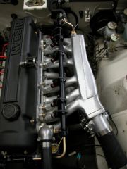
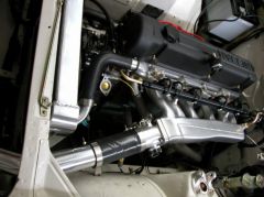
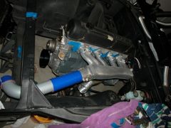
Here are some more pics of the work in progress. The engine is a stock 240z bottom end that revs very quickly to 8000, With 10.5 Compression ratio and a MSA 2003 cam it made 210hp at the rear wheels. I sent the plenum to Rebello when he was doing the port work on my turbo head. He tested it and said it should flow enough for 450hp with the GT30 I was planning on using. Dave said he has seen NA cars with heavily ported stock plenums like this making 300 + HP. If you compared the stock insides to what I was able to remove below, I don’t see how it could not help BTW I also changed the flange to a 6 bolt set-up for the earlier heads as well as injector bosses in the runners. You can also see how the TB flange has been angled to help flow into the number 1 runner as well as provide a straight shot to the core support for straight 3" tubing. Jeff -
-
-
-
The rear bumper is made in 3 pcs and glassed together, because of the undercut. Like said above, most glass parts will not be perfect. I installed mine after doing some sanding and re-fitting, and am quite happy with them. If this is not what you expected, I agree you should call them, they have good customer service and will help find a solution.
-
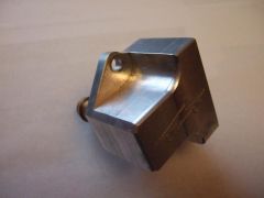
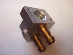
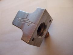
Here are some pics of the adapter body from Electromotive.
-
-
-
-
-
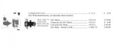
The one Electromotive sells is remote mount. It takes a GM style IAC motor and has 2 hose barbs on it. These can be plumbed into the plenum and before the TB. Check out the Electromotive catalogue http://electromotive-inc.com/pdf_files/Catalog.pdf page 13. I have an extra one of the Chevy style adapters. Would you be interested in it? I don’t remember what I paid for it, but I will make you a good deal. Jeff
-
I'm confused, what’s so funny about reverse cooling a Z head??
-
Yet another Rear control arm design
MONZTER replied to tholt's topic in Brakes, Wheels, Suspension and Chassis
So with this new rear design, could you lower the rear inner control arm point, thus increasing the anti-squat -
Now you should see the price. I can dream
-
Well, like some many projects, it’s good to have friends. One of my friends own a CNC shop, and we trade time with each other. I do some engineering work for him and he'll trade me CNC time. This really is the only way to make a project like this possible. So, to put a number on it? A typical good rate for CNC programming and run time in Southern California is $60.00 an hour. This part took 67 hours to program and run. with 45 of that being pure run time (so this would be the time for a second part) Now material. The chunk for the back started out at 95lbs x $4.00 plus for prime plate and the front chunk was 50lbs. Once again My friend had some "scrap" from a previous job, I bought it off him for scrap rate which is $1.00 a pound. So if you start to do the math without the special good guy pricing, you'll see this would cost more than some peoples cars. Completely ridiculous and impractical for the gains I hope it will make over a set-up like everybody else is using. I personally think making more of these from CNC would be a waste of time and resources, it just happened to be convenient for me to do it. Seriously, look at car like TimZ and JeffP’s cars and the power they are making with much simpler to construct manifolds. I only hope to be where they are. I really like to think of this project, and my whole engine for that matter as exercise in fabrication, completely impractical, and overdone. But, for me enjoyment, a hobby. I am glad everybody likes the parts, and appreciate the nice comments, I’m sure some of you can take this concept in a different direction and make it practical. I think Kevin from accurate injection was looking into it. I will eventually be doing a thread on the complete engine build, stay tuned. Jeff
-
Have you seen this company http://www.jenvey.co.uk/ check out the advice and FaQ's section. It has some answers to your questions Below is some info from that page What is the best throttle body diameter? Factors influencing size are; Power output, RPM, cylinder head design, cylinder capacity, position of the throttle body in the inlet tract and position of the injector. Choice of bore size is a balanced compromise resulting from the following; 1) A larger bore leads to lower flow resistance, but obeying the laws of diminishing returns. 2) A smaller bore leads to better throttle control and response (never underestimate) and improved fuel mixing. 3) The system should be considered in total - from (at least) trumpet flange to cylinder and proportioned accordingly. Basic references for BHP per cylinder, assuming ca 120mm from butterfly to valve head and a max of 9,000 rpm are; Up to 30 - 30mm, up to 33 - 32mm, up to 39 - 35mm, up to 46 - 38mm, up to 51 - 40mm, up to 56 - 42mm Up to 65 - 45mm, up to 74 - 48mm, up to 80 - 50mm, up to 87 - 52mm, up to 93 - 54mm. These power figures may be increased by up to 10% in a purpose - designed and well proportioned system. As butterfly to valve distance increases, butterfly size will need to increase in proportion to system taper and vice versa. Lower revving engines and those with injectors placed before the butterfly will generally accept a larger body. What is the correct overall system length? Induction length is one of the most important aspects of fuelling performance engines. In our experience an under-length system is the greatest cause of disapointment, with loss of up to 1/3 of power potential. There are a number of good books on the subject and the serious developer is referred to these and, in particular, dyno trials. A guide figure, from the face of the trumpet to the centre of the valve head is 350mm for a 9,000 RPM engine. Other RPM are proportional, i.e. for 18,000 RPM the figure is ca 175mm. Any air feed system to an airbox or filter can have a large effect on the power curve and must be considered carefully - particularly if the airbox is small. The induction system is part of a resonant whole - from air inlet or trumpet to exhaust outlet - and the ideal length is heavily influenced by the other components. What is the best position for the butterfly? The butterfly is an important aid to fuel mixing. When positioned too close to the valve this advantage will be lost whilst positioning far away may lead to a loss of response. As with the injector position (see below), higher RPM demands a larger butterfly to valve distance. A practical minimum figure for a 7 - 9,000 RPM engine is 200mm, whilst the maximum is dictated by the need to fit an air horn of reasonable length to achieve a good overall tract shape. One solution to this apparent compromise is the use of bodies with fully-tapered bores which, in effect, extend the trumpet distance beyond the butterfly and into the manifold. For very high speeds above approximately 15,000 RPM, the ideal butterfly position is only just inside, or even outside the trumpet and a point is reached where a taper is no longer sufficient for good tract shape. For these circumstances we can supply bodies with the exponential trumpet shape machined into them as a special service, or barrel bodies which, by their nature, must be purpose-designed in conjunction with the cylinder head. Where is the best place for the injectors? Where one injector is to be used per cylinder the best compromise position is immediately downstream of the butterfly. This gains maximum advantage from local turbulence and gives results surprisingly close to the optimum at both ends of the rev-range. This is the recommended position for most applications For performance at low RPM, economy and low emissions the injector needs to be close to the valve and firing at the back of the valve head. This is the favoured position for production vehicles. For higher RPM (very approximately 8,000+) the injector needs to be near the intake end of the induction tract to give adequate mixing time and opportunity. The higher the RPM, the further upstream the injector needs to be. As a result, use of speeds above approximately 11,000 RPM may give best results with the injector mounted outside the inlet tract altogether (see our remote injector mounting). It is common to fit both lower and upper injectors in such a system to cover starting and low RPM as well as high speeds.
-
Daeron, OTM did mention the Vortex generators, and for me I did not understand what he meant, because the vortex was what I was trying to get rid of. Sometimes, it takes a few things to make an idea click. So now, looking back at his post, ya I see what he meant and he was correct. Good job OTM for being the one to spot it, I wish I had got it sooner In regards to the ribs moving during welding? If you look at the pictures of the CNC halves you will see 8 1/4 inch pin holes for dowels that will be inserted before welding. These dowels will Keep the two halves from shearing relative to each other. Also, the ribs are 4mm thick, plenty stiff, and the walls are 1/8. I am not worried about that. Molds, you know that would probably be easy, the problem is not making the parts, its everything else. My turbo is in a totally different location than stock, and I don’t even know if a stock location turbo would fit under there. Then there is the vacuum log, BOV, fittings, throttle bodies, Intercooling plumbing, ect…. Basically, what I am trying to get at is everything is 100% custom, and so much work would have to be done to make this a useable product to the masses. I think it is a great product for a one-off have fun design/fabricate exercise. Production compatible? I don’t think so. You know, I often think about the guys who get all the credit for building those one of a kind hot rods. Heck, making 1 of anything is easy. Let see them make a production run of those cars, oh ya and make them reliable, safe, and environmentally responsible. The true masters are the guys at the major companies who pull that off for the masses, now that’s talent Remember, Design is an exercise in compromise, the one with the least wins Jeff
-
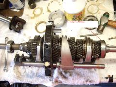
Click the pictures to enlarge. Early 240sx I believe 89 down cars use mechanical speedos and mine hooked up with no mods. The cross member definatly needs to be modified as it sits further back
-
-
-
Let me explain how I built the bar. First the flat spots on the chassis is not parallel, so trying to cut/miter the cross tube perfect for welding is a pain in the arse. So what I did was cut a 1-3/8 hole in the mounting plates that allowed the bar to slip through it. Given the mounting plates are 1/4 thick, this gives you some easy tolerance and makes a square saw cut possible. Next I "threaded" the mounting brackets over the bar, and bolted the brackets to the chassis with precision thickness 3/8 washers between the mounting plates and the chassis. I did this to add a little more wiggle room to make installation easier. After bolting in the brackets with the washers in place the bar is perfectly aligned and ready to tack. After tacking the bar I removed it and welded it 100% on the table. So the thickness of the washers could be adjusted to compensate for different "alignment" problems with different cars. So, that’s how I would do it, any comments?
-
Thanks guys. But the problem is always “if the price is right" and there is nothing wrong with that. Really, I have no interest in making a couple of bucks, or even a bunch of bucks of anybody on this forum. This is my hobby that I do for enjoyment, If I were to make some parts it would be more to help people out who don’t have the equipment to fabricate their own parts. That being said, I also am not going to lose money, by making some parts. Really, by time you consider laser cutting the brackets from 1/4 CHMO plate, doing a heavy tumble to remove the scale, buying the CHMO tube, building the fixture, welding the parts, chroming or powder coating them, it’s not going to be cheap, I don’t think anything that is done nicely is. What if I made you guys some prints of the brackets, and of the cut length of the bar, this way you could make your own with whatever means you have. It would really be much cheaper, and keep with the spirit of this forum, building hybrids.
-
I usually make these kinds of parts just for myself, but its such a simple part. I'll think about it and let you know. Jeff