
74_5.0L_Z
-
Posts
1209 -
Joined
-
Last visited
-
Days Won
34
Content Type
Profiles
Forums
Blogs
Events
Gallery
Downloads
Store
Everything posted by 74_5.0L_Z
-
 Thanks, I still have to do the final sanding. I can't wait to get this painted.
 -

Aerodynamics DONATIONS NEEDED!!!
74_5.0L_Z replied to Mikelly's topic in Windtunnel Test Results and Analysis
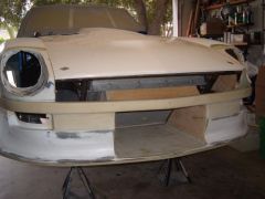
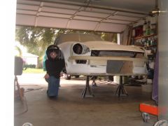
I don't think that the aero mods that benefit the racer and that benefit the average street driver are mutually exclusive. I think that we are going to find that some of the simplest mods will net the best overall gain. For example, closing up the front radiator opening and controlling where the air goes will reduce overall drag and reduce front end lift. The same goes for enclosing the inner wheel wells (not covering them). I hope that we will establish a baseline for a stock bodied car and then progressively make changes to see the results. Add headlight covers Add different air dams Add rear spoiler(s) Change ride height/angle I have faith that that we will all be happy with the results. By the way, I have been doing some work to my car in hopes of reducing its drag and improving its front end lift. Here are pictures that shows my progress (and my daughter). My next order of business is to close off the area above the bumper and modify my hood to vent the radiator air (very similar to Terry Oxendales hood). -
-
 I have modified the subtle Z air dam by adding a bottom that extends to the front crossmember, adding a mouth that is sealed to the radiator, and molding in a bumper feature that better fits the contour of the headlight buckets.
 -
Aerodynamics DONATIONS NEEDED!!!
74_5.0L_Z replied to Mikelly's topic in Windtunnel Test Results and Analysis
I'm in. -
So far, I love the Odyssey battery. I moved it to the shelf behind the passenger seat. By changing to this battery, I was able to remove 30+ pounds from the car. Also in doing so, I have reduced the polar moment and lowered the CG (just a tiny bit).
-
S30 Aerodynamics not really that bad?
74_5.0L_Z replied to rudypoochris's topic in Miscellaneous Tech
The number that I used in my Quarter2.xls program should not be taken as gospel. It is a number that I arrived at by analyzing the coast down graph published in the 1970 review of the 240Z by Car and Driver. What I did was pick two point on the coast down graph (80 mph and 20 mph) and estimated the slope of the curve at those two points. The slope of the coast down curve at any point corresponds to dV/dt. Using the instantaneous accelerations at those two points, I solved the following : m*dV/dt=CdA/2*Rho*V^2 + Cr*V + C In this equation dV/dt was estimated from the graph at two points. V is the velocity at the two points chosen. Rho is the density of air C is a constant value that I used to account for the force needed to start the car moving from rest on a flat surface. The variables CdA and Cr are the drag coefficient times frontal area and the static rolling resistance. The units of CdA are ft^2 and the units of Cr are lbf/mph. One factor that I neglected in my original analysis was the inertia of the wheels and tires. To account for this the inertia of an original equipment tire, wheel and brake assembly would have to be measured and the equations would need need an additional term. m*dV/dt + I* dw/dt = CdA/2*Rho*V^2 + Cr*V + C where the term I x dw/dt is the mass moment of inertia of the rotating parts times the change in rotational velocity. Although I was trying to be as accurate as possible, it should be remembered that I made the Quarter2.xls program for fun. Even neglecting the inertia of the rotating assemblies, I believe the number to be accurate within +/- 15%. As stated on the downloads page, I welcome input to increase the program's usefulness and accuracy. Dan -
Cage design outside the box
74_5.0L_Z replied to WHP's topic in Brakes, Wheels, Suspension and Chassis
My roll bar is angled back at a 10 degree angle, and is hard against the wheel well. This angle puts the roll bar parallel to the trailing edge of the front part of the quarter window. -
Cage design outside the box
74_5.0L_Z replied to WHP's topic in Brakes, Wheels, Suspension and Chassis
I am in the process of replacing the stock seats with aluminum racing seats with the side bolsters. This in combination with padding should go a long way towards protecting my ribs. Oh yeah, I do have 5-point harnesses in the car. -
Cage design outside the box
74_5.0L_Z replied to WHP's topic in Brakes, Wheels, Suspension and Chassis
I had similar design requirements. I have more several images in my album. http://album.hybridz.org/showgallery.php?cat=500&ppuser=7833 -
Fits fine if the engine is installed in the same position as mine.
-
Be careful with that last statement. Don't be too cheap. Stay away from the KYB gas struts. They are cheap, but are way too stiff in bump and too loose in rebound. I am using the Koni 8610-1149 with 250 lb/in rear/ 200 lb/in front. I don't find the ride very harsh, although I don't drive it on the street very much. If your going cheap then get the cheap konis or illuminas.
-
Whats one thing thats makes your Z different from the rest....
74_5.0L_Z replied to a topic in Miscellaneous Tech
I can't quite put my finger on it..... -
-
-
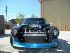
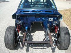
Front end on the day that the welding was finished
74_5.0L_Z posted a gallery image in Members Albums
-
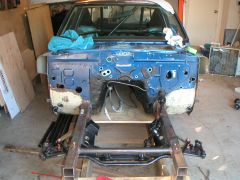 This photo shows the car after I cut off the original front end. The wooden structure holding the car was made to fit tightly betwee the original frame rails and extended back past to point "C" as shown on the factory frame drawings.
 -
I have made one other set for someone else, and I have a fixture for making more. I am a little shy of making them for others to to the possible legal ramifications (I am not an LLC). The other issue is price. It costs me ~$400.00 to make these ($300.00 in materials and $100.00 to have them welded). In this thread, I discussed the control arms at length: http://forums.hybridz.org/showthread.php?t=91888&highlight=control+arms
-
can someone build or design in CAD air horns for me?
74_5.0L_Z replied to JaysZ's topic in Fabrication / Welding
Try these guys: http://www.velocity-of-sound.com/commerce/search/index.php3?merchant_id=2107&keywords=&search_type=ANY&custom_store_category=8&by_category=+++GO%21++ They look interesting, especially if I were making my own. -
I knew that was true for the thin 4130. I just wasn't sure about the 4140 due to the higher carbon content.
-
I used 4130 for my control arms. 4140 has more carbon content and is therefore less weldable and more prone to crack if not subjected to PWHT. Johnc is much more knowledgable than I on this subject, and I hope that he will correct me if I'm wrong.
-
Reverse the master cylinders. The smaller master cylinder applies more force than the larger one.
-
My pedal is fairly light, and the clutch disengages about halfway through the pedal throw. I have a Wildwood 7/8" clutch master cylinder and a Tilton hydraulic throw out bearing. The details of my clutch set-up are in some of my older posts like this one: http://forums.hybridz.org/showthread.php?t=87797&highlight=clutch
-
My combination is set-up for autocross, so I don't use drag slicks. My car weighs 2700 full of fuel with me in it, and has ~320 hp at the rear wheels. I am using the king Cobra clutch disk and pressure plate. I have had no troubles with clutch slippage since I installed it. I don't know how this clutch would perform under hard launches with drag slicks, but for me it works well.