ISPKI
-
Posts
243 -
Joined
-
Last visited
Content Type
Profiles
Forums
Blogs
Events
Gallery
Downloads
Store
Everything posted by ISPKI
-
Hey all, My co worker got his hands on a to be junked subaru SVX for free. Was sitting in an abandoned shop building for a while that he acquired, hooligans came by and smashed out all the windows, interior got a ton of water in it, etc etc. Long story short, he is going to strip it for parts before junking it since these are fairly rare. I wanted to know if anyone has ever swapped the rear differential of an AWD SVX into a S30. I would be looking to swap it into my 77 280z which had been an AT car with an R180 open. It has been converted to a 5.0 5 spd and I am looking for a tougher rear end. From what I have read the AWD SVX has a possible Long nose CLSD R180 in it which I believe should be a 4 pinion and should stand up to my mild v8 power (shooting for 300whp, ~325ft/lbs). I realize there will likely be some customization work for the axles, drive shaft will be new anyways, maybe some mounting point fabrication but seems like it would be much easier than converting to a short nose R200/R230.
-
Do you happen to have a spare MT pedal assembly? Looking to convert my 3 speed AT to MT
-
I am converting my 77 280z 3 speed auto over to a v8 5 speed MT and am looking for a pedal assembly to use. Not sure which years can work.
-
I believe I may have mine from my 77 280z. I will check and get back to you.
-
What are your plans for the 2jz?
-

77 280z resurrection mod Resurrectomod?
ISPKI replied to ISPKI's topic in S30 Series - 240z, 260z, 280z
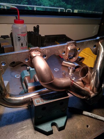
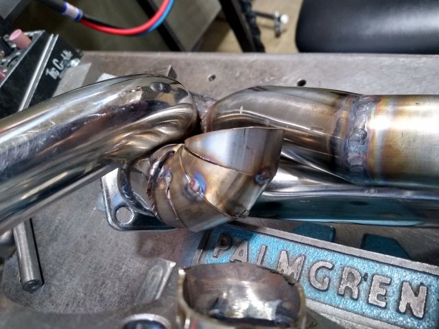
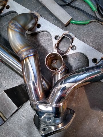
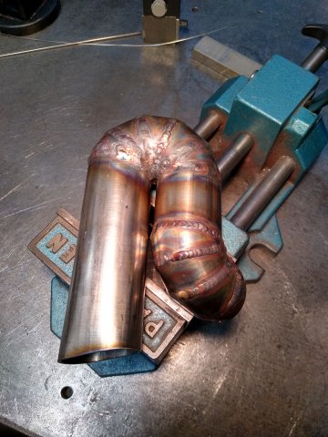
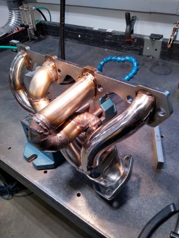
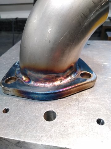
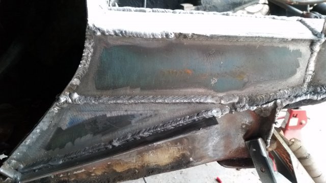
A few pictures of the work done to get these headers to fit my engine. This engine has the GT40P heads which have an odd spark plug angle. There was only one company making headers for these (ford) but they stopped making them years ago and the only ones I could find are many hundreds of dollars. Flow isnt going to be ideal but I have a new design I am working on that should be much more gradual. Also - Getting alot of tig welding practice in. I was finally getting the hang of it once I got to the collector flange.
-
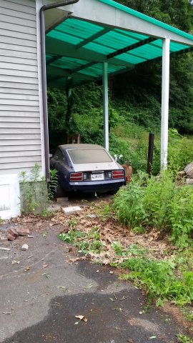
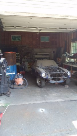
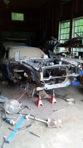
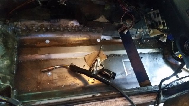
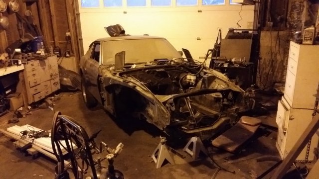
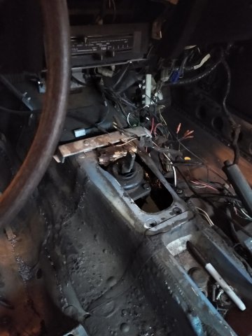
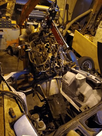
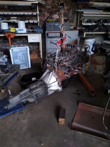
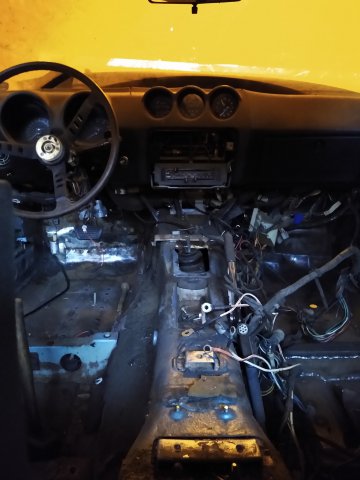
Hey all. So I have had my 1977 280z for around 7 years now. Drove it for a couple when I first bought it. Started having issues with the L-Jet system. Spent a while troubleshooting but the more I fixed the more I found items that needed fixing. Ended up moving into an apartment, then bought a house, sold the house, etc. barely worked on it for a few years. My now fiance and I bought a farm house with a big ole workshop (about 2500sqft, 3 bays, 1 dumptruck bay) and I got back into making my dream car just that. I decided now was the time to do it right. My Z had rotted floors, rotted frame rails, rotted fenders, rotted firewall. tons and tons of structural rot. Good thing I am a welding and metallurgical engineer and have plenty of fabrication equipment and experience (I hope). I cut out both floors, the firewall on the passenger side, fender well, and patched the "torque box" area of the frame in front of the firewall...one panel at a time. Most of these welds have been gas backed or flux shielded, or copper backed. Derek Macheski provided the floor support rails for my build (I think hes on here somewhere) as a partial trade for my motor. I am pairing my Z up with a Ford 5.0 small block V8. The donor vehicle was a 2001 mercury Mountaineer which means this is the highest performance factory 302W offered but also brings up some challenges; 1: The heads are GT40P heads which requires special or custom headers. The only headers currently manufactured that fit correctly are long tubes which will not fit the S30 engine bay. 2: The upper and lower intake are quite tall and require the engine be mounted somewhat lower in addition to possible hood clearance modification. 3: The engine is returnless and distributorless and I will be using the factory EFI harness and ECU, tuned with protune and probably a Moates QH chip. The current state of the build: I have completed most of the fabrication work, a few odds and ends that need to be finished but nothing major. I have the engine, transmission, and headers all in the vehicle and everything seems to fit. I am currently working on thinning the EFI harness of all unnecessary equipment using an old factory electrical schematic and some help from the folks over at the explorer forums.
-
Hey all, I am moving this project over to the member's project area since I am just about done with most of the major fabrication work and starting to work on electrical.
-
Possibly interested in the R200 long nose. Are you willing to ship it to CT?
-
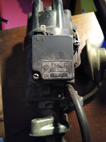
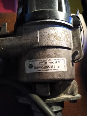
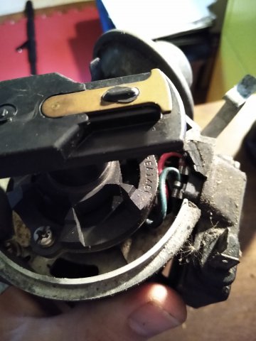
Here it is. Little dusty from sitting in its box for the last few years. I couldn't find the harness connector unfortunately but the internal wires are red and green
-
I am pretty sure I have a 79-83 non turbo 280ZX distributor that I had swapped into my 77 280z. Ended up selling the motor and no longer need the distributor. I am going to grab some pictures of it because I dont recall if it is a NON turbo 280zx distributor but from what I understood, that was the one used to swap into the S30 280z to eliminate the points ignition module correct? I "believe" it has a brand new magnet in it that has effectively zero running miles on it as I had replaced that and the stator years ago when I first got it (dont ask me for the source, I cant remember back that far D:). Either way, i'd love to sell it to keep someone else's car on the road.
-
Ya know mine in my 77 280z were actually not that bad!, I replaced a couple feet on the outside and about 10 inches on the top but the only area on the bottom that was rotted was right around where it met the firewall. The rest of the bottom appeared pretty OK all the way up to the engine crossmember. There is a divider piece inside the frame over in front of the firewall that was rotted out on mine which was extremely difficult to replace. Doing 1 panel at a time, taking your time and dont try to replace everything at once should keep that frame structurally sound, especially having the engine out of the front. My car is so light without the motor that I reposition it by lifting the nose and shifting it around my shoppe by hand.
-
That is definitely repairable on the surface but be prepared to have to replace at least twice as much as what looks rotted. Fortunately, that rot is forward of the engine cross member so I doubt you will have any structural issues. The inside can be extremely difficult to access, damn near impossible in alot of cases. I did a ton of repair work between the firewall and the cross member and I actually ended up cutting out the bottom of the frame in a long segment to make sure I got most of the rust. After welding in fresh coated steal, I drilled a hole open in the frame and sprayed in rust reformer, let that set up for a few days and then hit it with internal frame coating. Opening up the bottom of the frame all the way back to the firewall will give you access to the inside and let you determine what needs to be done. Fortunately, the vertical sides are what carry the load here, the bottom can usually be removed without compromising structural integrity as long as the motor is out of the car, which it appears to be. I would just assume that you will have to replace the entire bottom of the frame from half a foot forward of that rot all the way back to the firewall. It slopes down towards the firewall so if any moisture was trapped in the frame it would accumulate towards that area most likely.
-
Welp, I have hit a slight snag in the project. I fabricated the transmission crossmember and bolted that in. Everything is mounted up currently. I started running electrical stuff, fitting the harness, upper intake etc. My snag is when I tried to mount the upper intake, the rear bolt hole is hitting the hood latch at the firewall with almost an inch left to go on it. Also - This is a 2nd generation explorer motor with a taller, higher performance intake. The upper intake is a bit taller than the older EFI intakes and looks like it wont clear the hood. I will likely have to cowl the hood to an extent. I am now debating how to go about fixing all this and I am seeing a few different options. Option 1: I can cut off the hood release and mount the hood using hood pins. I will also need to cut and cowl the hood with a very mild cowl induction lift, maybe 1 or 2 inches. Option 2: I can shift the entire assembly forward an inch or two. This will require the most work, cutting up my engine cradle, redrilling all the mounting holes on the cradle and transmission cross member, find a shallow oil pan since my pan is about half an inch from the steering cross member, new oil pickup, etc. I *COULD* notch out the steering cross member to fit the pan since it no longer needs to carry the motor. Option 3: I could machine the intake about an inch shorter. I dont know if this will work since it floats over the valve covers and fuel lines and it will likely bottom out on something.
-
Well, ended up yanking the filter adapter out of the arm that was on the block, turned it down and it ended up working just fine. Picked up a bellhousing and fork for the T5 and got it bolted on and test fit into the car. Shifter comes thru the trans tunnel about an inch or two forward of the Automatic shifter location. I had studs in the top mounting holes of the bellhousing that were hitting the firewall so it will go back a little bit more once I get bolts in there.
-
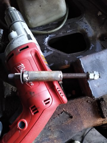
Having a hell of a time trying to install a summit oil filter relocation kit at the moment. Not really understanding how this snap ring is supposed to fit or how these inserts are supposed to line up or how I am supposed to remove the threaded nut from the block.
-
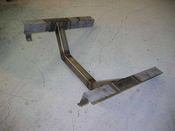
Yeah thats the design im doin. Good to know about the extra beef. I am going to do one thread insert in the frame tubes and just use a long bolt. That should be good enough and I will be able to remove them if need be. I ended up cutting the center section as my 45 degree tubes werent 45 degrees and the oil pan was bottoming out on the cradle. I reset the angle pieces to ~44.5 degrees, lowered the center tube by 2" and rewelded it. Did one seam inside the tube, then made some heavy 1/4" gussets formed on my anvil and welded those in. I think it should be plenty stout and the engine is resting at .1 degrees on both X and Y axis, should be plenty for the motor mounts to compensate for. I clamped and cross drilled a 3/8" hole in both mounts, locked them together with 3/8" bolts, and then removed the engine. Drilled a 2nd thru hole for a 1/2" bolt and then opened up the 3/8" holes to 1/2". I have the cross member in right now, just waiting to find a bellhousing before I drill the frame mount holes for it.
-
Nah no bushings on the cradle side. The other piece to this is a 2" wide steel "U" that will cross bolt through the 45 angular tubes. That "U" has a 9/16" hole in the top where the motor mounts on the engine will go. Using motor mounts out of a 1983 F150 with a 302. Seem to line up well and are vulcanized rubber mounts so I shouldnt need any bushings frame side. The "U" that Layne used were 3/16" plates folded to shape, mine are 1/4" groove welded on top with a 3/8" fillet weld inside. Should be excessively strong for the application. I have to try and get the engine into position with the "U" brackets bolted onto it, then once it's there, I will need to clamp the brackets to the cradle, unbolt the motor mounts, and then get in there and cross drill a pair of 1/2" bolt holes thru the cradle. Dont think I will weld nuts on the cradle just so I have a little adjustment when finally seating the motor. I dont think I want to do that until I have the transmission bolted to the motor so I can see how thats going to line up and my tranny is missing the bellhousing so that is the item I am looking for currently.
-
No, it is similar in design to Brian Layne's motor cradle with some minor tweaks (mostly mounting). I did not see if he used horizontal mounting points, all I saw in his write up were two top bolts plus one bolt thru the steering cross member. I am going to do 2 top, 2 sides, 1 thru the steering cross member. This is mostly due to the engine that I am working with being much newer and probably capable of putting out a little more power, plus I may procharge it down the road, who knows. Unfortunately, his drawings do not show the depth of the center cross member relative to the top of the side rails. I think mine is not quite as deep as his.
-
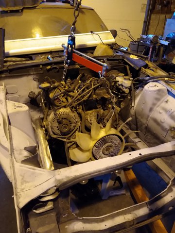
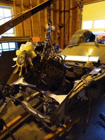
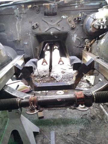
Hiya folks, I have been test fitting the 302 engine into my 77 280z. Following Brian Layne's instructions and designs with slight modifications for my particular engine and I have run into a slight snag. My motor is out of a 2001 mercury mountaineer. I need to lower the engine another inch on the motor mounts but I am bottomed out on the oil pan. I checked the oil pan that Brian has on his parts list which is marked as a Dual Sump pan, however it is not a dual sump pan when I look it up using the summit part#. Just wanted to know, is a dual sump oil pan shorter in that middle valley? The pan on my motor looks identical to the pan he put on his so I think mine may be a dual sump already. If I cant raise the oil pan depth by at least 1 more inch, then I will need to modify my engine cradle to lower the center section down.
-
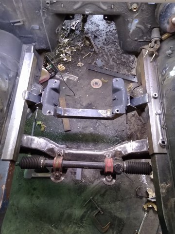
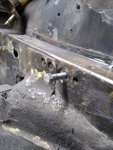
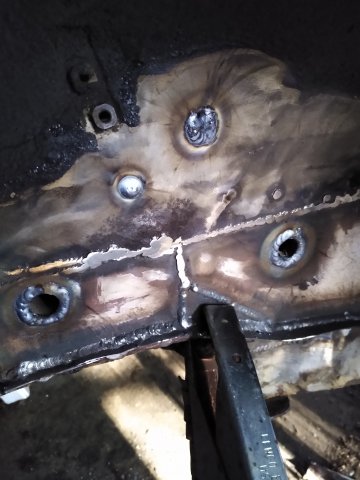
Arighty. So I spent some time shaving the brackets out of the engine bay, removing A/C lines and what not. I picked up my buddy's load leveller for the hoist and have the engine almost in position. However, the oil pan is touching the engine cradle and the motor mounts still need to come down another inch or so to line up with the cradle. I will have to wait to get it mounted until I can find a front sump or dual sump oil pan. In the meantime, I completed the frame insert tubes for the mounting studs on the driver side. Going to start working on the passenger side this afternoon.
-
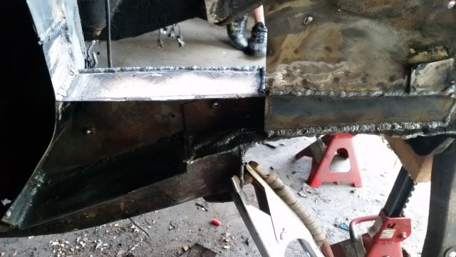
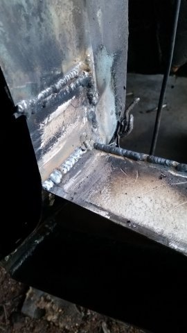
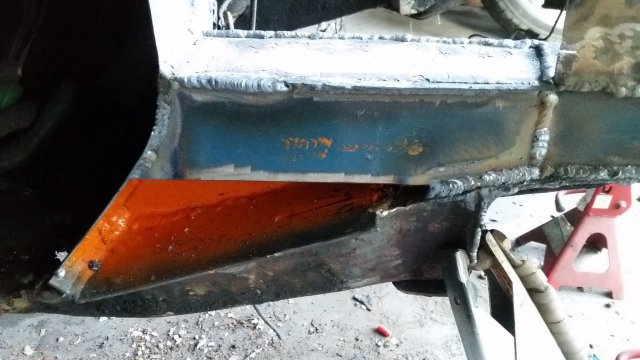
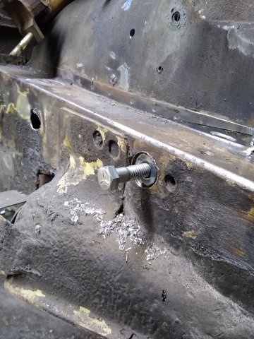
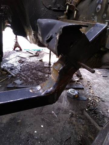
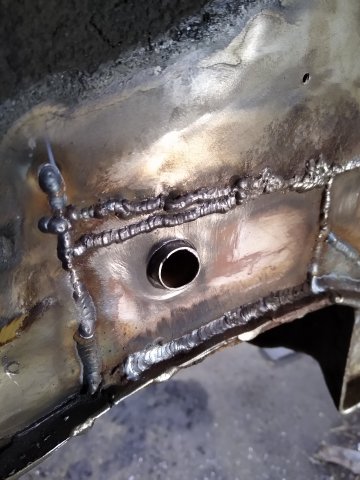
Here is how the frame inserts look. It was a real pain to weld into the bottom of the frame
-
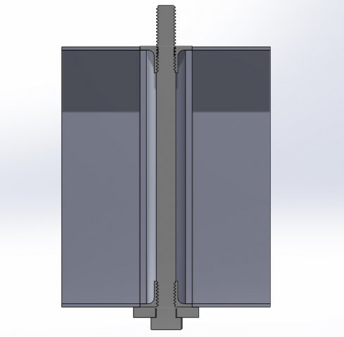
Awesome, glad to know im on the right track. I made one of the tube inserts last night out of some steel tube that I had laying around. Not super heavy wall but I bet it doesnt really need to be all that heavy. Seemed like maybe 1/16" wall thickness, 3/4" OD roughly. I think the thread insert on both ends of the tube adds a level of complication that isnt really necessary. I ended up having the thread insert on the top, pressed in a nut into the bottom of the tube, then threaded a bolt through both so it protruded out the top by about an inch. I then drilled 1" holes thru top and bottom of the frame and welded the insert into it. The bolt came out smack dab in between the steering rack cross member and the mount for the forward control arm(?), where that heavy rod mounts angularly thru the frame. Seems to be the strongest spot on the frame. Going to do another one closer to the firewall, 2 horizontally through the frame, and 1 through the steering rack cross member.
-
Thank you! your car in your sig looks fantastic! Been a bit but ive been working hard on the Z. Driver's side floor and floor frame support are welded in. Went a little better than the passenger side, the floor under the seat rails was not rotted the way the passenger side was so I only installed half the floor pan and didnt cut out the cross members, made for alot less work. I also test fit the 302 into the engine bay! I have Brian Layne's engine cradle print and fabricated the materials at work (CNC machining is so much nicer than grinding at home). I have the engine cradle all welded up and it fits beautifully. A little snug, I have to tap it in with a mallet to get it to seat all the way but that tells me its perfect. I wanted to ask people how they have fastened the engine cradle to the frame of the Z? I started by drilling and welding in thread inserts inside the frame but now that ive done a few and have seen how flimsy the frame material is, I wonder if I should go about it a little differently. Here is my thought; Drill thru top and bottom of frame. insert a steel sleeve spanning the ID of the frame and weld it in. Weld a thread insert top and bottom of the tube. Install a long bolt from bottom up (3/8-16 big nuff?) so that it protrudes out the top by about 1/2-3/4" functionally acting as a stud. When threading thru the thread inserts, the bolt should push or pull the thread inserts together, applying compression force to the welded tube inside the frame. That should transfer as much load from the engine cradle as possible. Attached is a drawing of what I am thinking.
-
So I have had the Z on hold for a bit this winter unfortunately. Finished up a bathroom in the house and fixing the fueling system on my log truck, but I am back at it! Last night I cut out the driver side floor frame and spent a solid hour in 7 degree temps grinding away the rubber insulation and paint to prep the weld areas for welding. Finished the night test fitting the floor panel. Tonight, I am planning on finishing the weld prep and continue fitting the floor pan. Also taking a slightly different approach to this side. My floor area under the seat rails is actually solid on this side, just a bit of surface rust here and there so I cut up to the flange of the forward rail. I am planning on cutting the floor pan with a 1" tab that will slip under the remaining floor and running a small bead across the bottom of that.